The logic level is a level of abstraction where logical operations are performed. On this level within an integrated circuit, signals are being converted, or combined, to turn into other signals. In digital electronics, signals are expressed in binary numbers where ground voltage is represented by a ‘0’ and positive voltage is represented by a ‘1’. By feeding these binary signals into tiny units called logic gates, they get processed in different ways depending on the type of logic gate.
Logic gates are very small building blocks of a digital system. They perform logical operations on one or more input signals and they produce a single output. They combine these binary inputs and apply a certain logic to them so that a certain binary output is created. For instance, a 2-input AND gate outputs ‘0’ except when both inputs are ‘1’ at the same time.
This chapter presents the different types of logic gates, how circuits are designed to create logic gates, and how gates are used to design larger functional blocks in integrated circuits. In digital processors, all operations are done by complex internal units that are created by combinations of logic gates. The overview below shows the most common two-input logic gates and their operation.
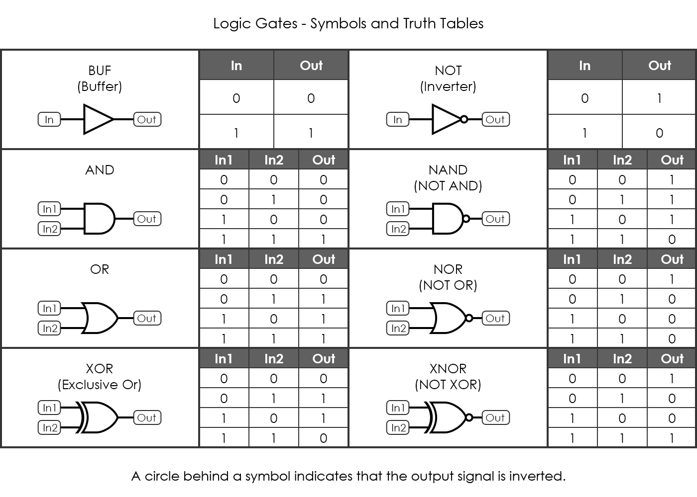
A buffer passes its input directly to the output without changing it. The main purpose of a buffer is to regenerate the input by using strong high and a strong low signals. This can be required if the input signal is not as strong and cannot directly be passed on to other components. A buffer has one input and one output, and its output always equals its input.
A NOT gate, also referred to as an inverter, produces an output that is the opposite to its input. Therefore, its behavior is the opposite of a buffer. If the input is high (1), the output is low (0), and conversely when the input is low (0), the output is high (1).
A 2-input AND gate outputs a high (1) signal only when both inputs are high (1), otherwise it outputs a low (0).
A 2-input NAND gate outputs a high (1) so long both inputs are not high (1), otherwise it outputs a low (0).
The OR gate outputs a high (1) if any of its inputs are high (1), otherwise it outputs a low (0). Note that the output is also high (1) when both inputs are high (1), as it is sufficient that at least one input is high (1).
The NOR gate outputs a high (1) only when both inputs are low (0), otherwise it outputs a low (0).
The XOR gate (Exclusive-OR gate) outputs a high (1) only when one of the inputs is high (1) exclusively, but not both. In other words, it outputs a high (1) only when both inputs differ. Otherwise it outputs a low (0). This is a difference to the OR gate where also both inputs can be high (1) in order to turn the output high (1).
The XNOR gate (Exclusive-NOR gate) outputs a high (1) when both inputs are the same, otherwise it outputs a LOW.
Some of the gate symbols have little circles attached. These circles always indicate a logical negation. This means, for instance, that the NAND gate is the exact opposite of an AND gate, and therefore the NAND gate symbol consists of the AND gate symbol but has a circle attached. Also note that on the symbols, power connections are not shown. Gate symbols always only include input and output connections.
The functionality of logic gates is realized by certain arrangements of electrical components within an integrated circuit. Nearly all of today’s digital integrated circuits use transistors for the creation of logic gates, but there have been numerous other approaches in the past, using transistors, resistors or even diodes to design circuits that function as logic gates. These different designs of electronic circuits are called logic families.
A logic family is a specific approach to create an electrical circuit that performs a certain logical operation by using a certain technology. Different types of logic families use different components and different circuit configurations, but ultimately achieve the same results as the circuits perform the same logical operations. As long as two circuits belong to the same logic family, they have identical electrical characteristics, and are therefore electrically compatible with each other. It is primarily due to historic reasons why many different logic families exist.
During the 1960s, a very popular logic family was called Resistor-Transistor Logic (RTL). Logic gates that were designed with RTL technology used resistors and transistors for enabling their logic function. Resistor Transistor Logic for integrated circuits is obsolete from today’s perspective, but it has gained some historic significance as RTL technology was used for the CPU in the Apollo Guidance Computer to control the spacecraft.
In 1962, logic families called Emitter Coupled Logic (ECL) and Diode-Transistor Logic (DTL) have been introduced. Also around that time PMOS and NMOS logic families were invented. PMOS logic uses only p-channel MOSFETs to implement logic gates and other digital circuits. NMOS logic uses only n-channel MOSFETs to implement logic gates and other digital circuits. Introduced the 1960s as well, Transistor-Transistor Logic (TTL) TTL uses bipolar transistors to form its integrated circuits. TTL became a widely used logic family for integrated circuits and was rather polular until the 2000s. Another logic family, Integrated Injection Logic (IIL) was used in some integrated circuits, but it is now considered obsolete. Last but not least, there is a logic family called Complementary Metal Oxide Semiconductor (CMOS). CMOS logic uses complementary arrangements of PMOS and NMOS field effect transistors. Introduced in the late 1960s, CMOS initially was slower than TTL. However, through the years of development, many advantages and favourable characteristics of PMOS and NMOS transistors have become evident, such as a smaller packing density, larger tolerance of higher voltages, low power consumption, and others. For that reason, CMOS has soon outperformed the other logic families. With its performance still increasing today, CMOS has become today’s first choice when designing digital integrated circuits. Two of these logic families, RTL and CMOS, are shown in further detail below.
Here is a set of circuits using resistor transistor logic to implement the most common logic gates.
Here is a set of circuits using CMOS logic to implement the most common logic gates.