The focal length is one of the most fundamental characteristics that describe an optical system. In a scientific context, focal length describes how strongly an optical system converges or diverges incident rays of light. In photography, focal length determines the field of view that a lens covers which in turn affects magnification, background compression, depth of field, and other visual aspects of the image. This chapter describes the optical aspects, the most common lens designs, and zoom systems.
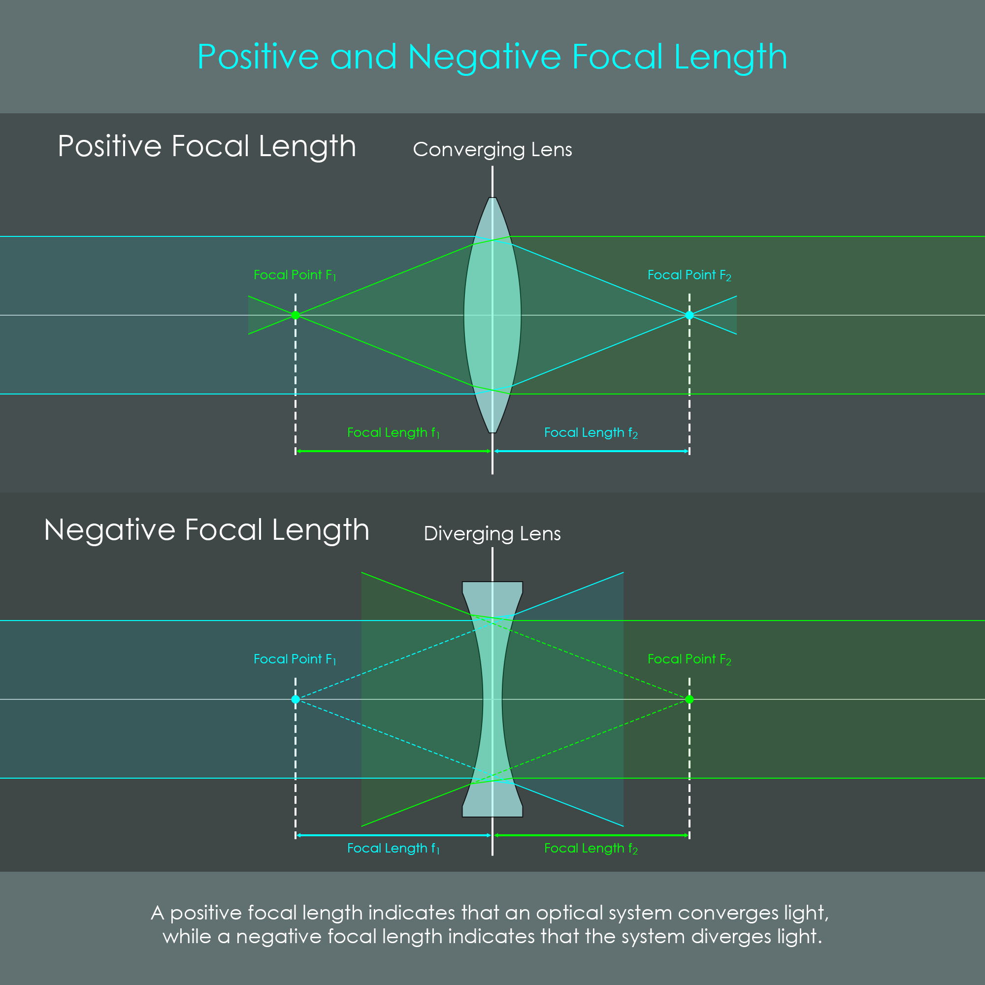
All optical systems – both an individual lens element and composite lens systems – has two focal points. A focal point describes at which location incident rays from an object at infinity (these light rays are parallel to the optical axis) coincide on the opposite side of the lens. Conversely, if an incident ray of light passes through one of the focal points before passing through the lens, these rays will be parallel to the optical axis when exiting the lens.
Focal length is the distance between one of the optical system's focal points and its respective principal point. Principal points will be described later in this chapter, however for symmetrical thin lenses, the focal length is usually the distance between one of the focal points and the center of the lens.
Refractive power (also referred to as optical power) is the degree to which a lens surface or an optical system either converges or diverges light. Refractive power can either be positive or negative:
The value of refractive power indicates how strong an optical system converges or diverges light:
In scientific terms, refractive power P is equal to the reciprocal of the focal length f of the optical system:
P = 1⁄f.
The refractive power of a single lens is approximately equal to the sum of the refractive powers of each lens surface. Similarly, for two or more thin lens elements located closely together, the refractive power of the combined lenses PC is approximately equal to the sum of each lens element's refractive power:
PC = P1 + P2 + Pn.
It should be noted that negative refractive power and negative focal lengths are mostly relevant for optical engineers who calculate the path of light through various different converging and diverging lens elements. Photographers, on the other hand, always use complete objective lens units that always have a positive focal length. That means that every photo or video lens is effectively a converging lens that forms a real image in physically reachable space, and lens names like 100mm are always positive.
In optics, principal planes are important reference lines that enable a simplified view of an optical system.
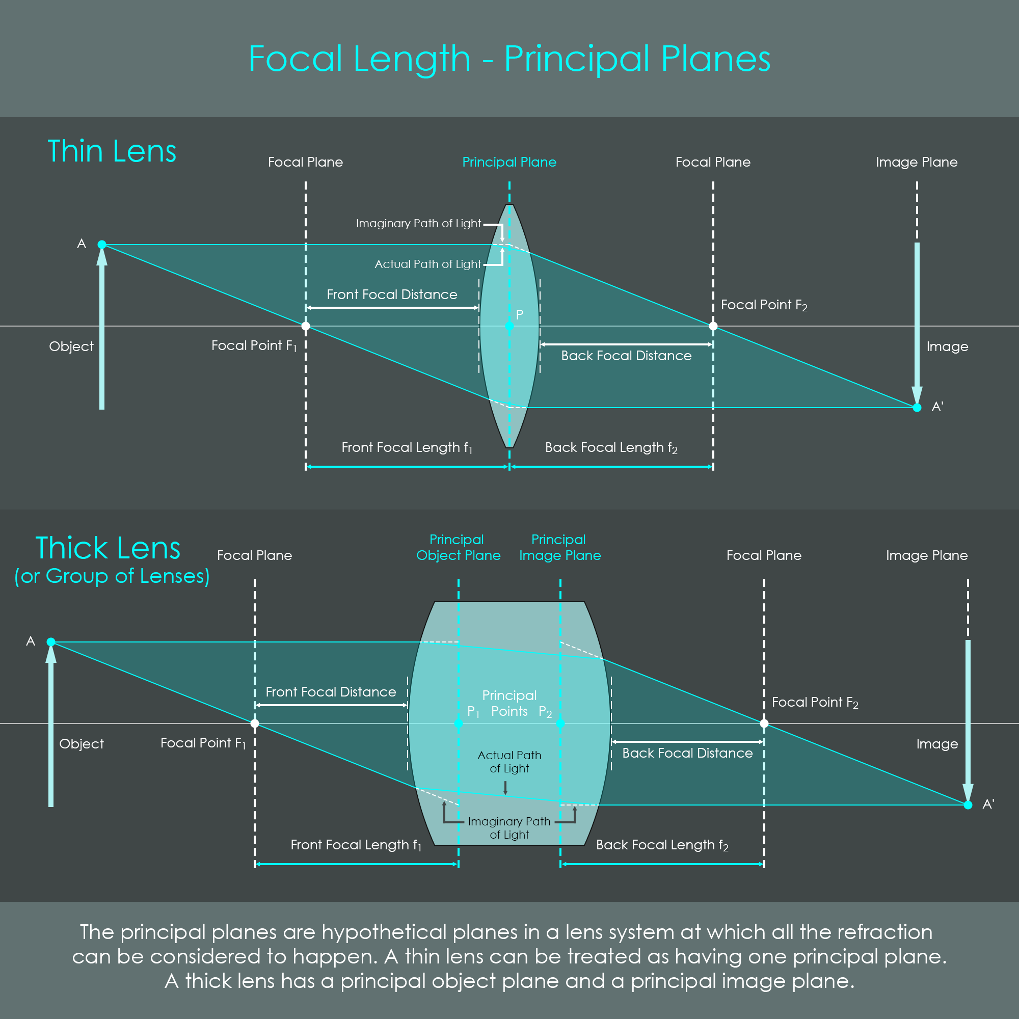
Principal planes are hypothetical planes in a lens system at which all of the refraction can be considered to happen. An optical system has two principal planes. The principal points P1 and P2 are located where the principal planes intersect the optical axis.
Thin Lens: An optical element may be considered a thin lens if the thickness (the distance d along the optical axis between the two surfaces of the lens) is negligible compared to the radii of curvature r1 and r2 of the two lens surfaces: d ≪ | r1 | and d ≪ | r2 |. A thin lens can be treated as having both principal planes in the same location, or simply having one principal plane (and one principal point). The distance between the principal point P and one of the focal points is the focal length of the lens. The principal plane allows to simplify the actual path of light from two refractions per ray to one refraction at the principal plane.
Thick Lens: An optical element that has a non-negligible thickness is a thick lens. Such a thick lens has a principal object plane (primary principal plane) and a principal image plane (secondary principal plane). The focal length is the distance between principal point P1 and focal point F1, or between P2 and F2, respectively. With two principal planes, the lens can be treated as if all of the refraction happened at the principal planes, and rays travel parallel to the optical axis between the planes.
To avoid confusion, there should be a clear understanding that the focal plane and the image plane are separate entities. Under normal conditions, a photographic lens forms an image further behind the focal plane because photographic subjects are not always at infinity. Only when the lens is focused at infinity, the image plane is in the same location as the focal plane.
In optics, a differentiation is normally made between items in front of the lens (in object space) or behind the lens (in image space). Therefore, an optical system can be described using the terms front focal length and back focal length, even though both distances are usually identical.
In contrast to focal length, the focal distance is related not to the principal planes but rather to the vertex points of lenses.
These terms should be used with care, as in some literature the expressions FFL and BFL are used to describe what is actually the FFD and BFD.
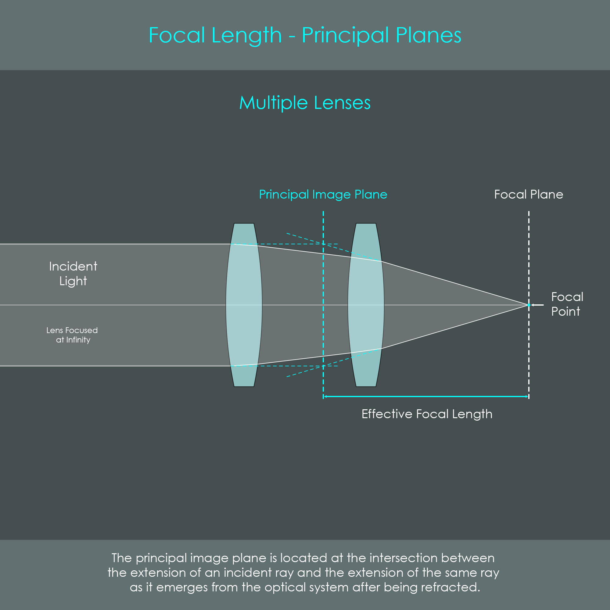
In optical systems with several lens elements, the principal image plane can be located using a simple technique. All that is required is to draw an incident ray of light parallel to the optical axis and to know the path of the emerging ray which exits the rearmost lens element. The incident ray of light is extended. Similarly, the same ray of light exiting the optical system is extended. Where the two extended lines intersect is the location of the the principal image plane. This technique can be used to determine the principal image plane of any optical system.
In such a multi-element optical system, the distance between the principal plane and the respective focal plane is often called the effective focal length, indicating that the system in its entirety has an actual focal length even if the individual sub-elements have different focal lengths.
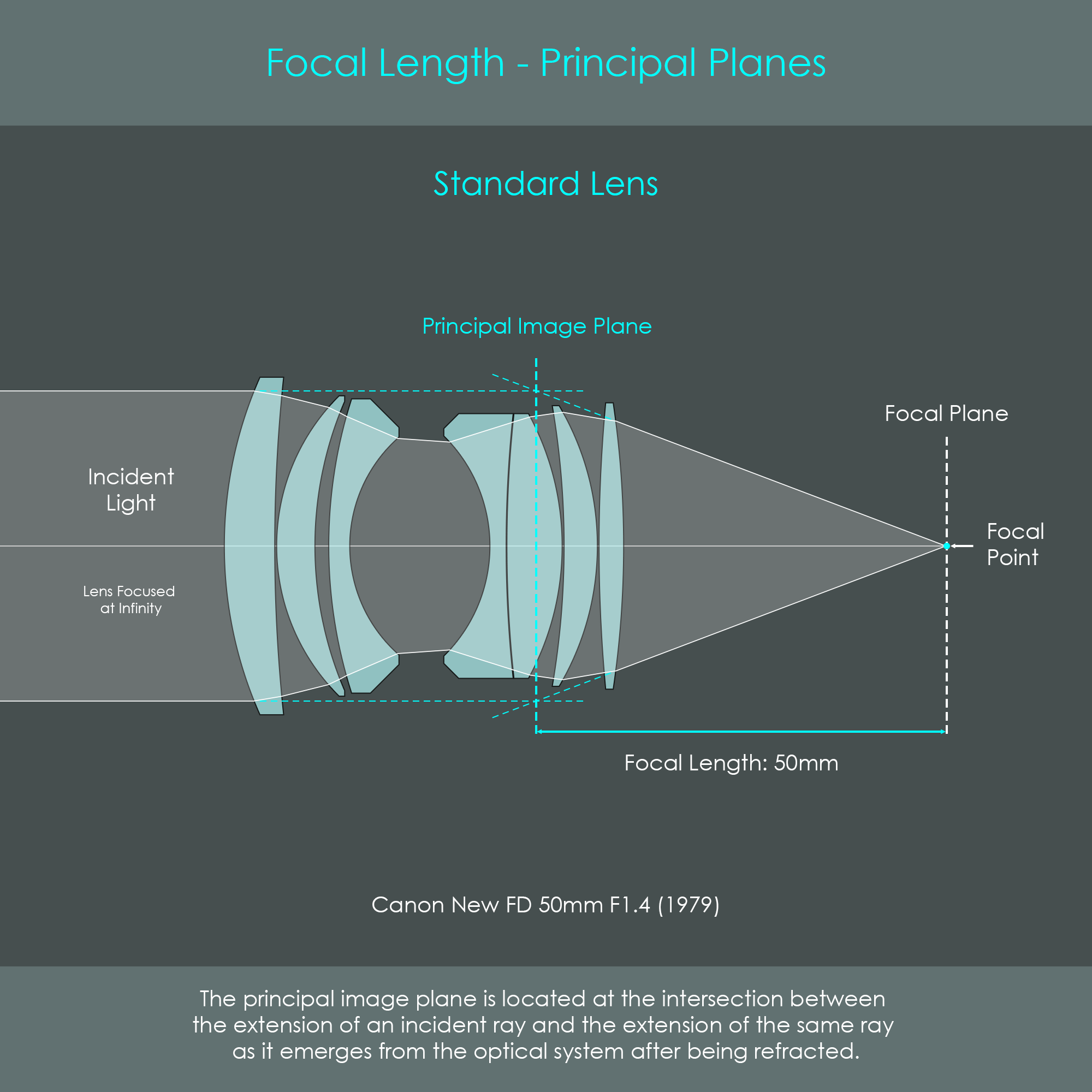
The real advantage of using principal image planes becomes very clear when looking at some actual lens configurations of Canon lenses. The illustration shows the principal image planes of a Canon 50mm standard lens. Solid lines show the actual path of light which is redirected by numerous individual refractions on lens surfaces and results in a rather complex shape. Using the principal image plane as a simplification results in an imaginary path of light refracted only once.
The technique to locate principal planes can also clarify how different lens designs affect the focal length of an optical system.
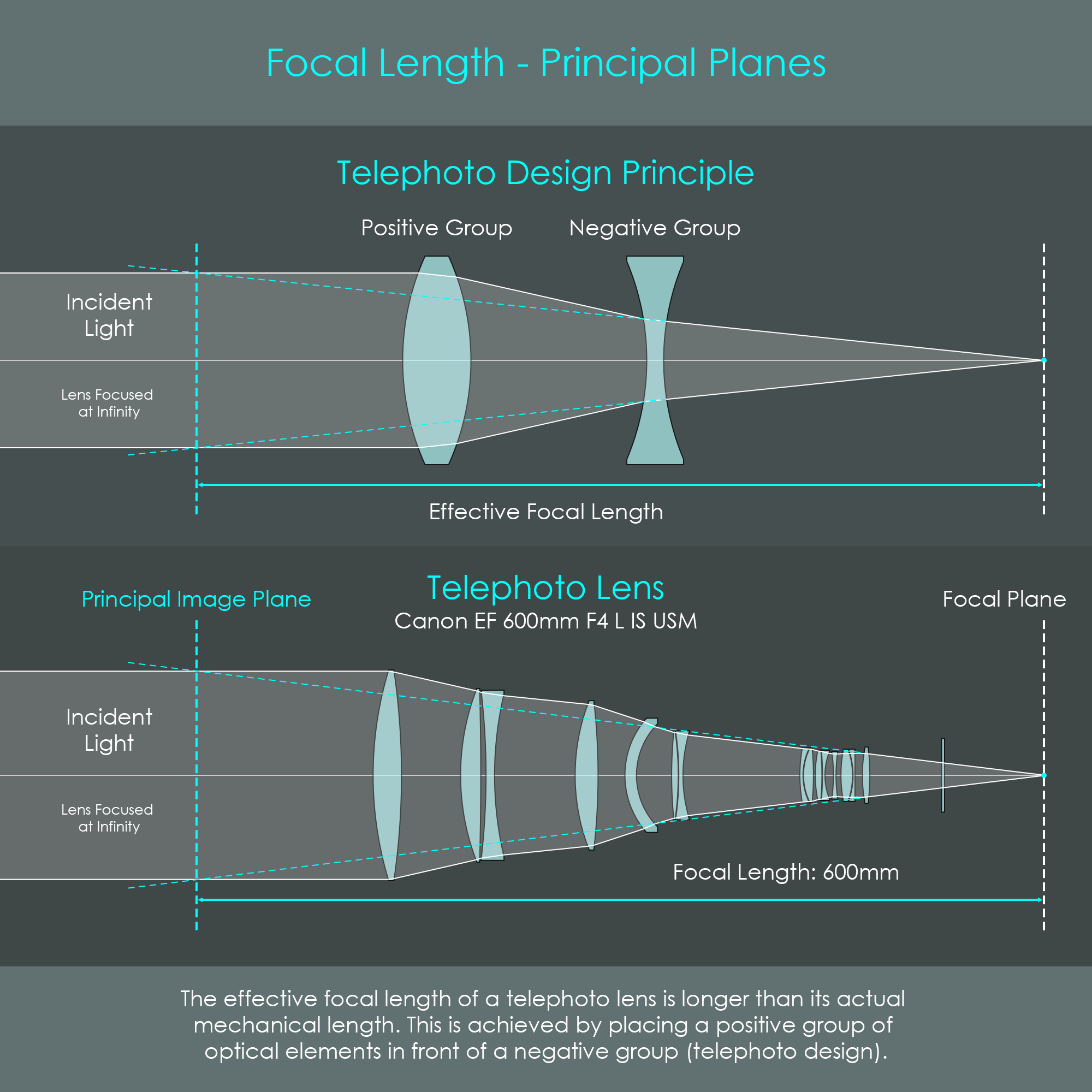
The principal image plane of a telephoto lens is outside (in front) of the optical system. While this appears unusual, it is actually the requirement and defining property for such a lens. A telephoto lens is defined as having a longer effective focal length than its physical barrel size. This is achieved by its special optical design: The front group of optical elements in a telephoto lens has positive refractive power and a focal length that is shorter than the effective focal length of the entire lens. The converging rays of light exiting the first group of optical elements are then slightly diverged again by the second group of optical elements – also referred to as telephoto group – so that they are still converging but at a smaller angle. This creates a narrow cone of light emerging from the system. When these emerging rays are extended, they will intersect with the incident rays of light in front of the entire system.
This design keeps even super-telephoto lenses acceptably compact and portable while delivering focal lengths of up to 1200 mm.
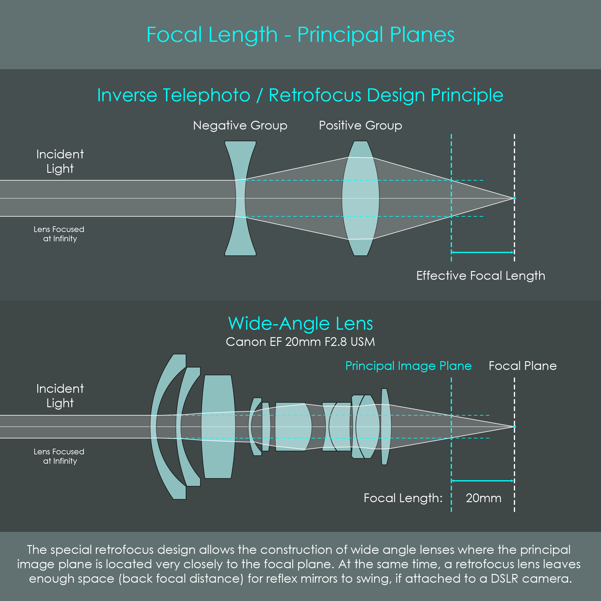
Wide-angle lenses have a different challenge to solve. They are characterized by extremely short focal lengths such as 20 mm. If a conventional convex optical element was used, that lens would have to be placed only 20 mm in front of the camera's image sensor. Unfortunately, in DSLR cameras, this space is required for the reflex mirror to swing, and therefore a conventional lens cannot be used. By a clever arrangement of optical groups, an optical system can be created that offers a short effective focal length while keeping the space behind the optical system (back focal length) sufficiently long for a reflex mirror to fit in.
A negative power group is placed in front of a positive power optical element. The first group diverges light and creates a wider sized beam of light. The positive group converges these rays onto the image sensor. Extending the incident rays of light causes an intersection far behind the optical system, creating a very short focal length. As this configuration is the exact opposite of a telephoto lens, this type of lens design is also referred to as reverse telephoto or retrofocus.
Photographers who read the focal length on their lens barrel usually do not think about the distances between principal points and focal points. In photography, the focal length is strongly linked to the viewing angle a photographic lens captures. This section explains wow a single distance determines the angular field of view (AFOV) that a photographic lens offers.
The AFOV is the maximum viewing angle that a certain camera system captures when it forms an image. That viewing angle is defined by the focal length of the used lens in relation to the size of the camera's image sensor. The AFOV covers the part of the object which is formed as an image across the image sensor diagonally. This viewing angle is specified in degrees and can often be found in the datasheet of a lens. A viewing angle specified in a datasheet of a lens usually refers to the AFOV that is covered by the image circle of a lens. Canon's EF lenses are designed with image circles that cover a full frame image sensor whereas Canon's EF-S lenses have image circles that cover the smaller APS-C sensors.
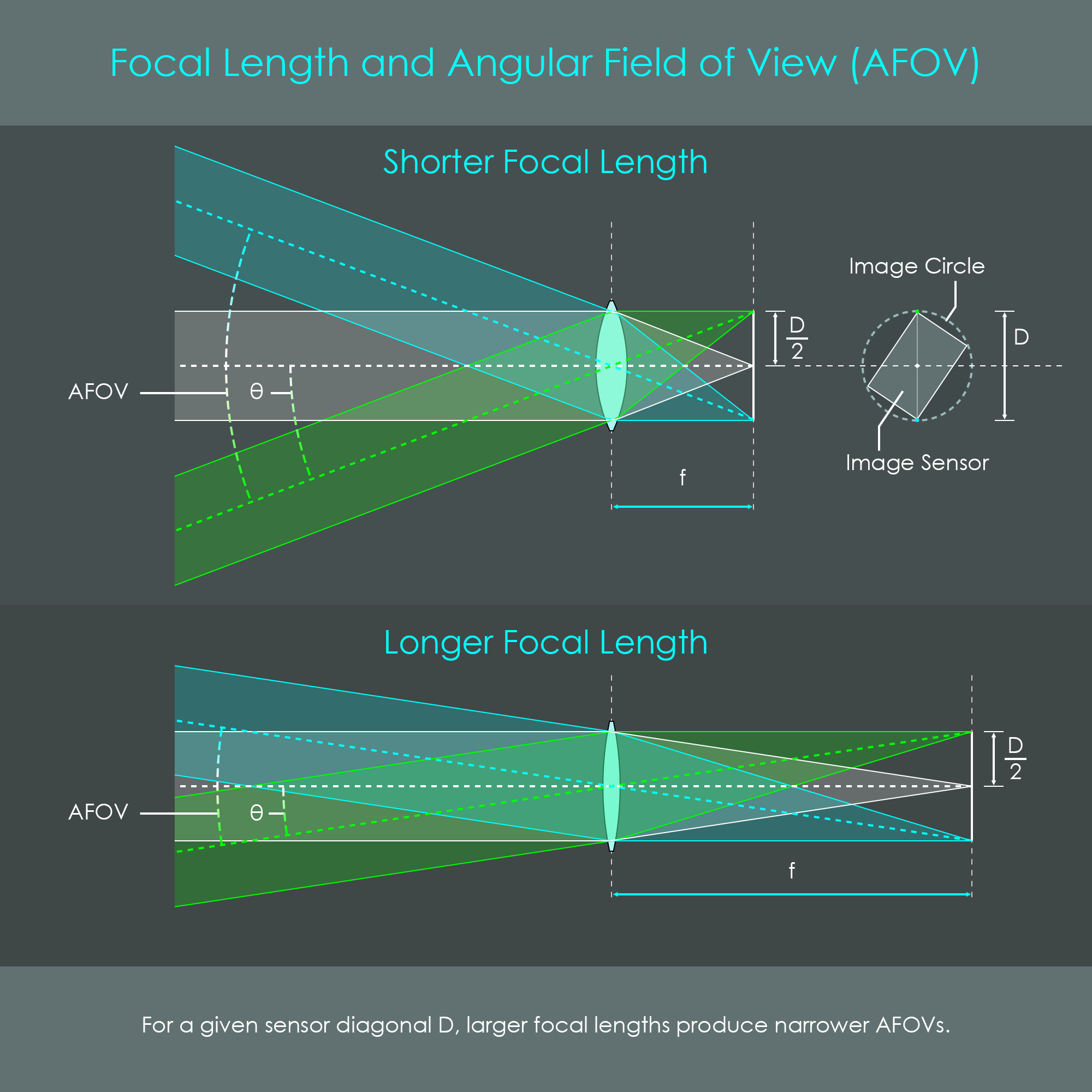
The relationship between sensor size, focal length and field of view can be expressed via the formula
D⁄2 = f × tan(θ).
D⁄2 is half of the sensor diagonal. The angle θ (Theta) describes half of the AFOV. For a given sensor size, the following formula can be used to calculate θ:
θ = arctan (D⁄2 f).
Consequently, the complete angular field of view is calculated using the formula
AFOV = 2 × arctan (D⁄2 f).
For example, when a photographic lens with f = 200 mm is used to form an image on a full frame sensor (D = 43.27 mm) the resulting image covers a viewing angle of 12.4 degrees.
This geometrical relationship explains the following observations:
It is worth mentioning that a change in AFOV related to sensor size does not indicate that the lens has changed its focal length. The focal length of an optical system is always determined by its optical design. This means that a 200 mm lens maintains its focal length regardless of the size of the image sensor that is used to capture the image. However, a smaller sensor size like an APS-C sensor (DAPS-C = 27 mm) narrows down the AFOV to 7.7 degrees. This creates a similar AFOV as if a 320 mm lens had been used on a full frame sensor. Using a Canon APS-C sensor instead of a full frame sensor reduces the AFOV by a factor of 1.6. That factor is generally referred to as crop factor.
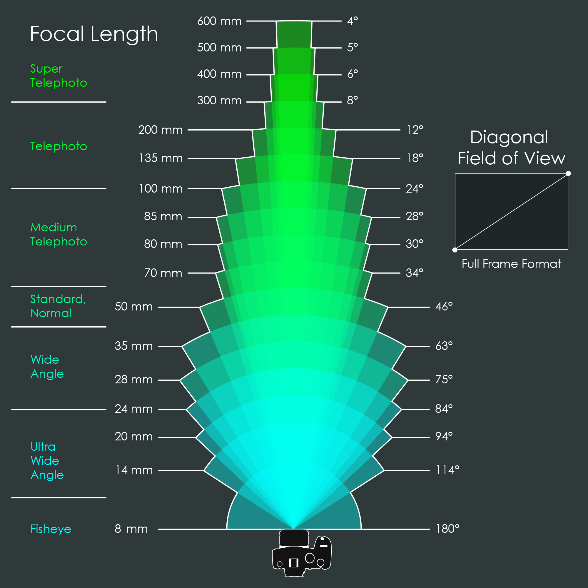
Solving the above AFOV formula for the focal lengths most commonly used in photography results in a variety of angles summarized in the illustration below. Depending on their AFOV, photographic lenses can be categorized into seven focal length groups. Lenses with ultra-large viewing angles of up to 180 degrees form one end of the spectrum, and these are called fisheye lenses. Ultra-wide-angle and wide-angle lenses are less extreme but they are designed to cover large viewing angles as well. Lenses that offer a viewing angle that is roughly equal to the human field of vision are called standard lenses or normal lenses. Lenses with particularly narrow AFOVs are at the other end of the spectrum, and these are called telephoto lenses. They can be subdivided into medium-telephoto, telephoto, and super-telephoto. It should be noted that focal length groups are not sharply defined and transitions between the groups are rather smooth.
The following illustrations show the actual path of light as it passes through some photographic lenses.
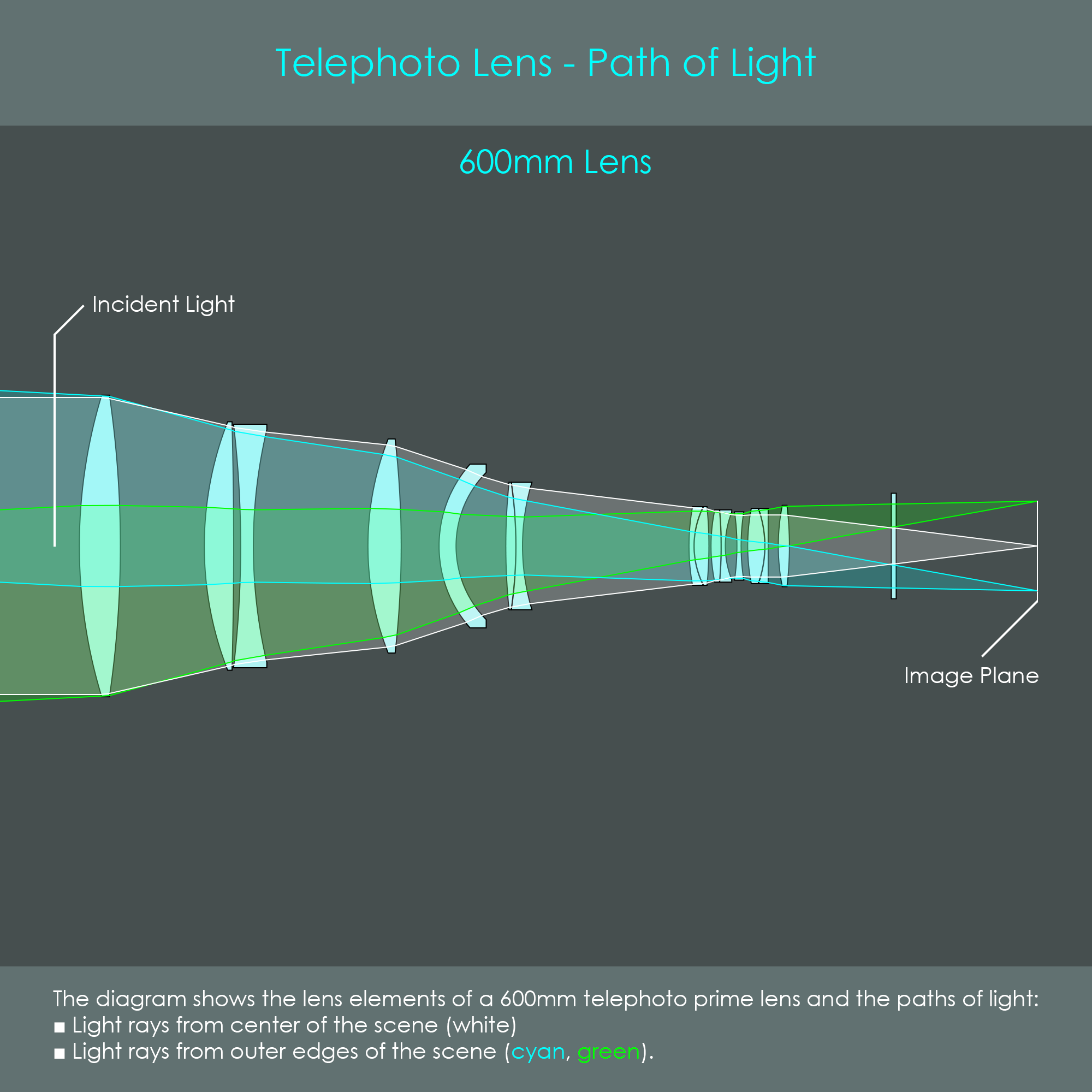
Telephoto lenses are mainly used in wildlife and sports photography due to their large magnification of the scene. The illustration shows a 600 mm super-telephoto prime lens that has an AFOV of 4 degrees. Although 60 0mm is a really powerful focal length, Canon has added 800 mm and 1200 mm options to their RF line of camera lenses. As the design includes an additional group of optical elements, telephoto lenses are usually the heaviest and most expensive lenses and can be priced over USD 20.000 USD (price checked on 04/29/2024).
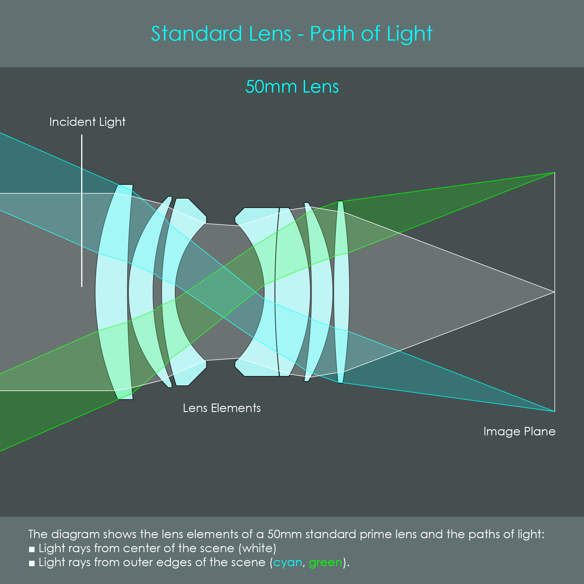
A photographic lens is called a standard lens when its focal length is roughly equal to the diagonal of the camera's image sensor. For that reason, when using a full frame camera system, lenses with a focal length of 50 mm are generally called standard lenses. Their angular field of view is almost similar to the human field of vision and provides a naturalistic look with very little distortion. They can offer some really attractive advantages such as low size and weight, and large apertures that offer excellent low light performance as well as high depth of field control. Therefore, standard lenses are good general-purpose lenses and are very popular in travel and street photography, or when shooting events, portraits, close-ups and other subjects.
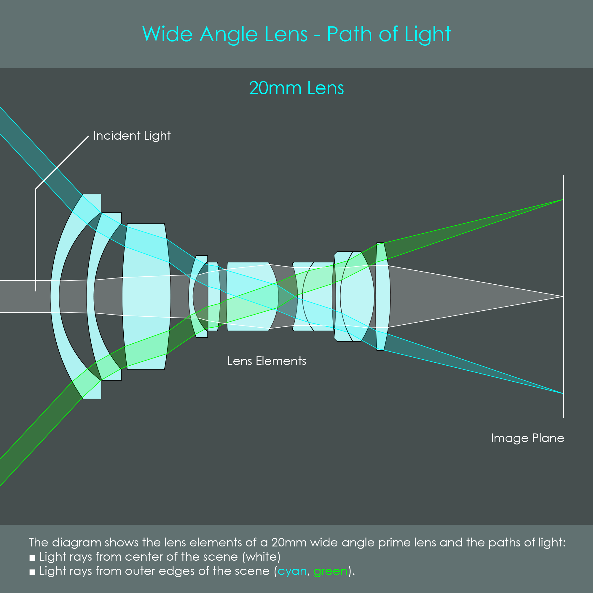
Wide angle lenses are designed to capture larger portions of the photographic scene than standard lenses. They are ideal choices for landscape and architecture photography. On a full frame camera system, any lens with a focal length of 35 mm or lower is considered a wide-angle lens, while 24 mm and lower is considered an ultra-wide-angle lens. Unfortunately, wide-angle lenses very often suffer from barrel distortion and vignetting, both of which can be corrected during image-processing.
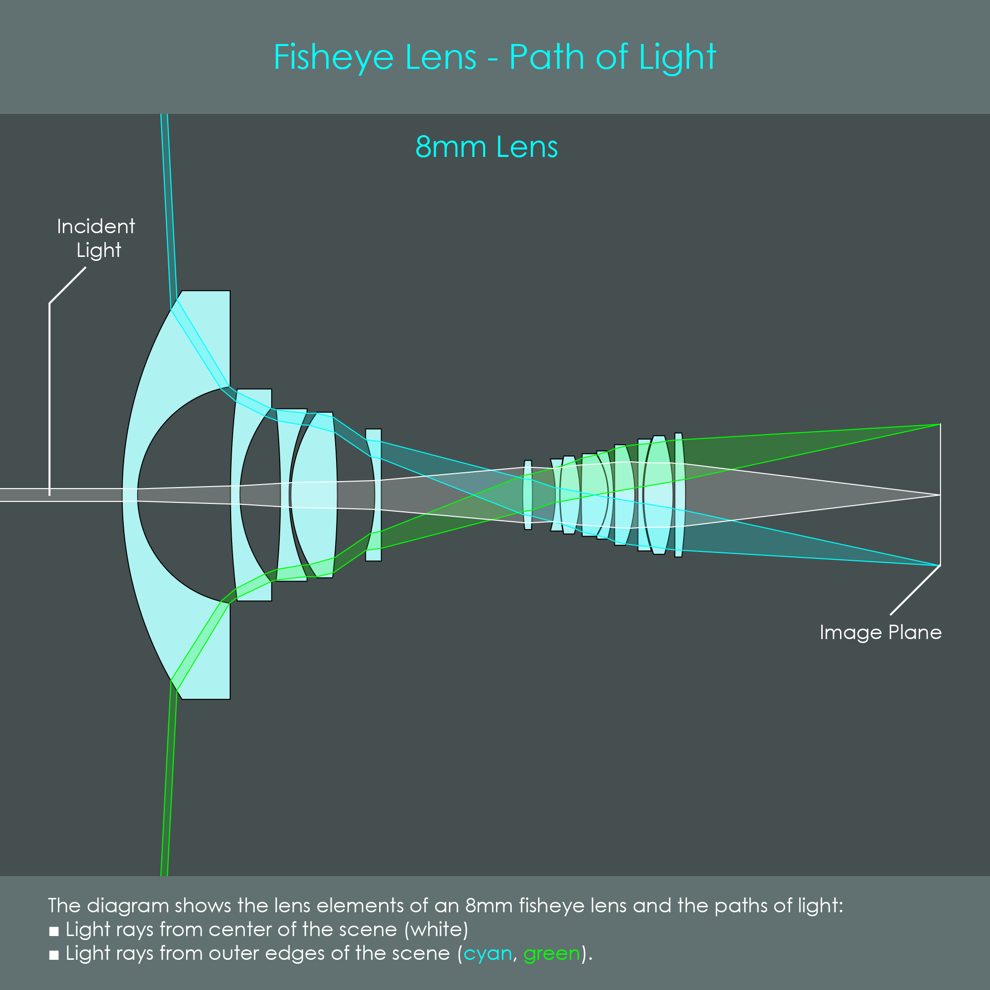
Fisheye lenses capture extremely wide angles of view, well beyond any rectilinear lens. Here is some background: Rectilinear lenses form images where straight features of an object, such as windows of buildings, appear on the resulting image with straight lines. Fisheye lenses, by contrast, produce strongly distorted projections of the scene which is a result from the extremely large angular field of view. This creates a very distinctive photographic look. Fisheye lenses have been invented in 1906, and the name originates from the idea that fish would have an equally distorted hemispherical view from underwater. These types of lenses are actually used in underwater photography or astrophotography where no straight lines need to be considered, but they can also be used to create artistic shots of other subjects.
A photo or video lens either has a fixed field of view or it can adjust its field of view to a certain extent. This results in two categories: Fixed focal length lenses – very often called prime lenses – and variable focal length lenses. This chapter explains the pros and cons of each type.
Fixed focal length lenses, also known as prime lenses, are photo or video lenses that only offer one focal length (and therefore only one specific angular field of view) that is pre-defined by their optical design. Any lens that has a name with only one particular focal length specified (rather than a range of focal lengths) is a prime lens, such as the Canon RF 100mm F2.8 L Macro IS USM, for example. In addition, the fixed focal length is also printed on the lens barrel in large letters - Canon EF lenses have '100mm' while Canon RF lenses only have '100' printed on the barrel.
While prime lenses are not flexible when it comes to focal length, they offer a number of serious advantages. Prime lenses often allow very compact optical designs with only around six to seven optical elements. This not only makes them relatively small and light but also allows designers to implement large aperture units. For that reason prime lenses are often very fast with F1.4 or even F1.2 as the f-stop values. This makes them great choices for photography in low-light situations. In addition, prime lenses are extremely sharp and show very little aberrations and distortion. This high level of imaging performance is achieved because optical engineers can optimize a lens system extremely well if there is only one focal length to consider. In terms of prime lens construction, the only moving optical element (or group of elements) is the focusing lens. All the other optical elements are fixed in place which also contributes to a high level of imaging accuracy.
Variable focal length lenses are designed to change the angular field of view by setting the lens to a desired focal length within a certain range. The user does this by turning a zoom ring on the barrel of the lens. The range of focal lengths that can be chosen depends on the lens model and is indicated in the lens name, such as the Canon RF 24-70mm F2.8 L IS USM, for example. In additional to the name, variable focal length lenses have the focal length range printed on their barrel in large letters – Canon EF lenses have '24-70mm' printed, while Canon RF lenses have '24-70' printed on the barrel. This lens can continuously change its focal length between 24 mm and 70 mm.
Optically, for a lens to change its focal length it needs to be designed with movable groups of lenses. By shifting groups of optical elements along the optical axis of a lens system, it is possible to continuously vary the focal length of the system. However, there are two different implementations of variable focal length systems – varifocal lenses and zoom lenses.
Any photo or video lens whose focal plane or back focal distance is not constant while changing the focal length is called a varifocal lens. This means that a varifocal lens requires refocusing after each change in focal length.
A lot of photographic lenses are actually varifocal lenses. This may sound like a problem, but in photography it is often not required to maintain the focus position when changing the focal length. In autofocus mode, pressing the shutter release button halfway on the camera quickly refocuses the lens, and the photo can be shot as usual. The design of a varifocal lens can help optical engineers to increase focal length range, aperture diameter, and reduce overall size and weight.
A (real) zoom lens or parfocal lens can continuously vary its focal length over a certain range and at the same time maintain a constant focal plane or back focal distance. This means that a zoom lens can keep a specific subject perfectly in focus while zooming in or out, and no refocusing is required. As this feature is critical when shooting videos, virtually every video lens is a real zoom lens. As all Canon EF and RF lenses can be used for both photography and videography, a large number of Canon lenses is also real zoom lenses.
In a zoom lens, the focal length is changed by moving axially at least one group of lenses – called the variator. To maintain the image plane in the same position, another group of lenses – called the compensator – moves at the same time to cancel out the resulting shift in focus. Thus, a zoom lens consists of at least two lens groups which can be moved along the optical axis. The following chapters go into the details of zoom system optics and mechanics.
Zoom lenses are very complex optical systems, and there are countless possible designs for zoom lenses. The most complex ones consist of more than 20 individual optical elements all driven by precision mechanics inside the lens barrel. Most of them, however, follow the same basic design principles.
Here is a short explanation of some terms that are frequently associated with zoom systems:
The zoom ratio is calculated by dividing the largest focal length of a zoom system by its shortest focal length. This means that a 100-400 mm lens has a 4X zoom ratio. While this zoom ratio offers a very intuitive way to describe the optical capabilities of a system, this factor is primarily used to describe camera systems with built-in optics (compact cameras, smartphones, etc.) or video lenses.
The zoom range describes the range of focal lengths a zoom system covers, such as 100-400 mm. It is expressed with two focal length values, one for the shortest and one for the largest focal length. Photographers who use interchangeable lens systems usually describe their lenses using the zoom ranges.
A simple 4-group zoom lens can be designed by installing an afocal zoom system in front of a fixed lens.
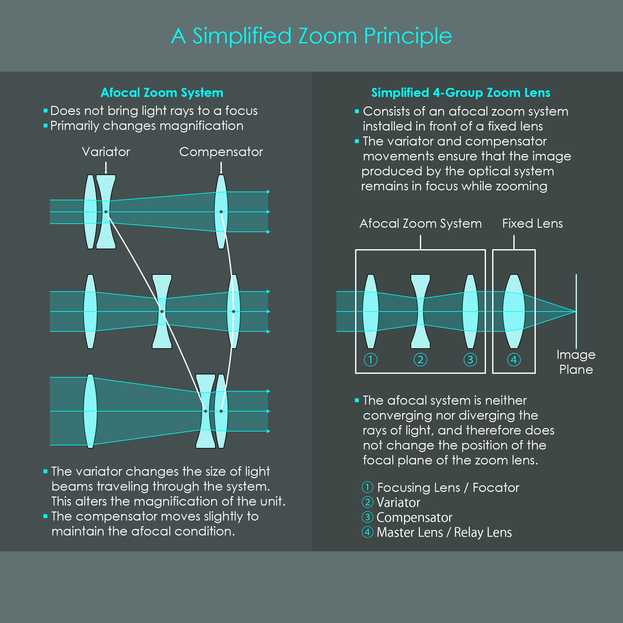
An afocal zoom system is an arrangement of optical elements that neither converges nor diverges incident rays of light. Instead, incident rays of light parallel to the optical axis that enter an afocal system – although getting refracted inside the system – remain parallel to the optical axis after exiting the afocal unit. Technically, this is an optical system with an infinite effective focal length. While this is an interesting feature, what really makes an afocal zoom system special is the ability to change the size of light beams traveling through the system, and therefore its ability to alter the magnification of the unit.
One lens of the afocal zoom system is called the variator and its movement changes the magnification. Another lens is called the compensator and its movement maintains the afocal condition of the system. The variator and compensator usually perform different movements along the optical axis when zooming. The variator is normally designed to perform a linear movement along the optical axis, and the trajectory of the compensator is typically nonlinear.
Looking at the illustration of the afocal zoom system, it is interesting to see that the top configuration with the variator on the left makes the front part a negative group that is located in front of a positive lens. This configuration is very similar to a retrofocus lens with short focal length. Conversely, the lower configuration with the variator on the right makes the back part a negative group that is located behind a positive lens. This configuration is very similar to a telephoto lens with a long focal length.
The illustration shows an afocal zoom system using three optical elements. This configuration is also called a PNP (positive-negative-positive) afocal zoom system, referring to the signs of refractive power the individual lens elements have. It should be noted that there are many other possible designs for afocal zoom systems. In the example shown the compensator is behind the variator which is a very common design. However, an afocal zoom system can also use the first lens element as the compensator element, but this results in the lens barrel to change its length when focusing. Alternatively, an afocal zoom system can also be designed as an NPN-type where two diverging lens elements are placed as outer elements and the converging lens element is used as the middle element.
The fixed lens, called the master lens or relay lens, is what ultimately forms an image on the image plane. This main imaging lens is responsible for the aperture diameter, focal length, and back focal distance. The position of the master lens is stationary, and the back focal distance remains the same over the entire zoom range. If an afocal zoom system can double its magnification when zooming, and it is placed in front of a 100 mm master lens, the overall zoom lens results in a zoom range of 100-200 mm.
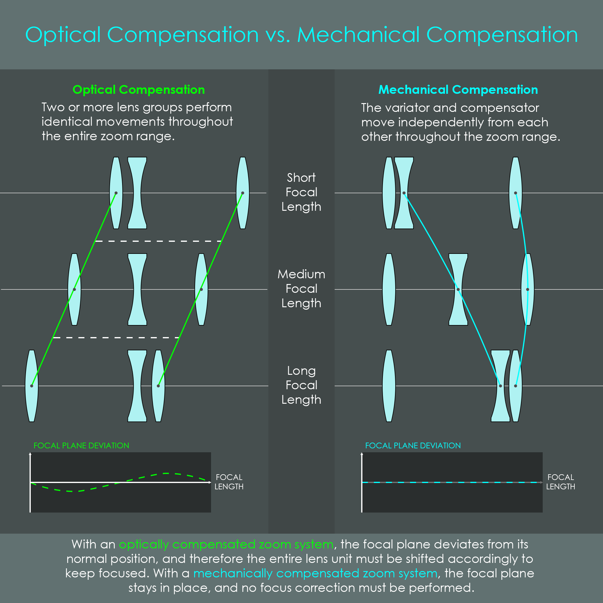
It is a key feature of zoom lenses that their focal length can be changed continuously and the image position remains in place. Over the past decades, optical designers have come up with solutions to minimize or even fully cancel out the image shift while zooming. In the design of zoom lenses there are two basic operating principles how optical elements can be moved:
The illustration is a comparison between these two approaches, and the lens trajectories are shown in green and cyan lines.
The illustration below is a block diagram of an actual 4-group zoom lens. The top part shows the wide-angle-configuration while the lower part shows the telephoto-configuration of the lens.
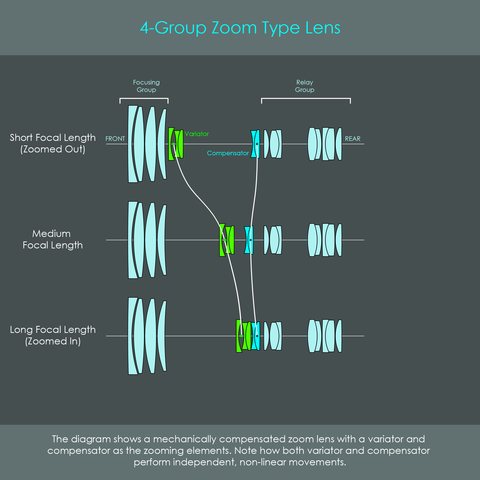
In this lens design, the front part is the focusing group, or focator, and it is used to focus incident rays of light from infinity at a finite distance. The variator group, or magnification variation group, is the group of optical elements that moves over the largest distance and changes the magnification of the system. Note how in this lens the variator does not perform a linear movement but has an individual motion path. The compensator, or correction group, moves slightly to counteract the image shift induced by the variator. In this particular lens design, the compensator combines two optical elements that results in a negative group, and therefore the trajectory of the compensator goes slightly towards the front of the lens while zooming. The master lens, relay lens, or image formation lens consists of eight optical elements. It is often the most complex group of a zoom lens because it is designed to counteract the optical aberrations that may have been induced by the other groups.
This type of zoom lens design offers a large focal length range and is very popular for video camera lenses and DSLR telephoto zoom lenses.
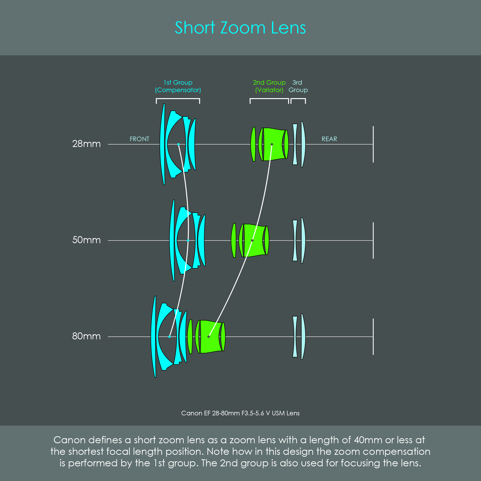
In the 1990s, Canon has introduced the EF 28-80mm F3.5-5.6 USM lens, a compact zoom lens design with only three groups of optical elements. Canon calls this design a short zoom lens as the shortest focal length is below 40 mm, a Canon-specific definition. The illustration shows the block diagram of the fifth generation of that lens, the Canon EF 28-80mm F3.5-5.6 V USM, hence the roman numeral V in the name. In this zoom lens, the first group of lenses is the compensator and has negative power of refraction, whereas the second group is the variator and has positive power of refraction. The variator also is the unit that shifts when focusing the lens. The stationary third group is the image-formation lens. By arranging a negative group in front of a positive group, the optical system does the exact opposite than a telephoto lens: The focal length is noticeably shorter than the physical length of the lens. This design is called a retro-focus lens. This type of lens construction is especially popular for wide-angle zoom systems.
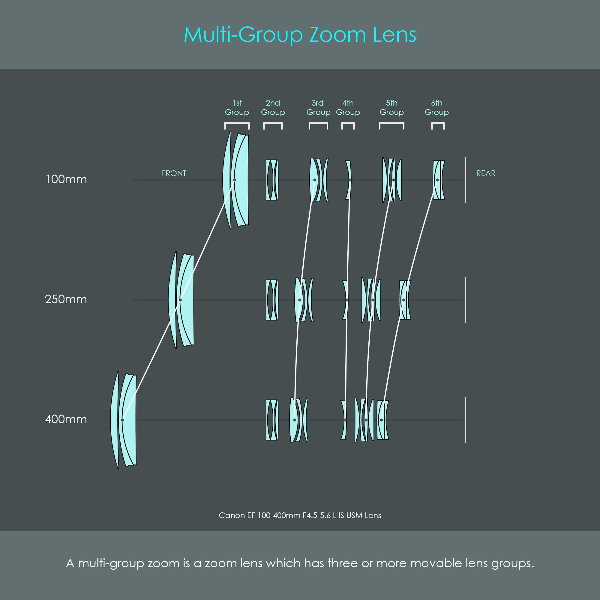
The zoom lens designs shown so far rely on two movable lens groups. By contrast, a multi-group zoom lens is a lens which has three or more movable lens groups. The illustration shows a block diagram of the Canon EF 100-400mm F4.5-5.6 L IS USM lens that consists of six groups, only one of these is stationary. Despite the high optomechanical complexity, there are some advantages of multi-group zoom lenses:
Today, a large number of Canon EF and RF zoom lenses are designed using multi-group zoom technology.
Zoom lenses can either have a fixed aperture (also called constant aperture) or a variable aperture. The main difference between these construction types is how the aperture value changes while zooming.
Zoom lenses can be categorized into external zoom and internal zoom lenses.
A zoom lens offers a great level of versatility and convenience. Many compact lenses with particularly large zoom ranges are often advertised as being ideal travel photography lenses. While this is true from a portability point of view, it is important to know that zoom capability may come with a drawback.
Optical designers of zoom lenses are always facing a trade-off between versatility and imaging performance. Prime lenses (zero zoom range) typically provide an above average image quality in virtually all aspects such as high resolution, low vignetting, low distortion, and low optical aberrations. Zoom lenses, as shown in this chapter, consist of additional optical elements to provide the zoom functionality. This causes additional refractions and a more complex path of light. Due to these additional optics, zoom lenses sometimes tend to have a slightly reduced resolution, slightly less contrast, or more veiling flare and ghosting. As a general rule, zoom lenses with a relatively narrow zoom range (such as 17-55 mm) tend to perform better in terms of imaging performance than zoom lenses with particularly large ranges (such as 28-200 mm).
Fortunately, over the past years, optics technology has advanced, and today's zoom lenses have caught up significantly in terms of imaging performance. Some of Canon's high-end RF zoom lenses perform almost equally well as prime lenses.
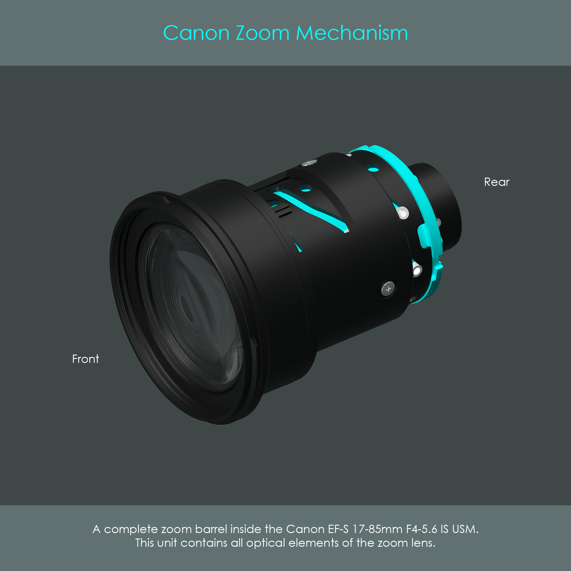
The illustration shows the complete zoom mechanism containing all the lenses optical elements as they are attached to the zoom barrel. Here. both of the zoom barrels – the helical slot barrel and the linear slot barrel – are covered by the long sleeve of the front element. There is an isolated view of these zoom barrel parts in the chapter about the lens barrel.
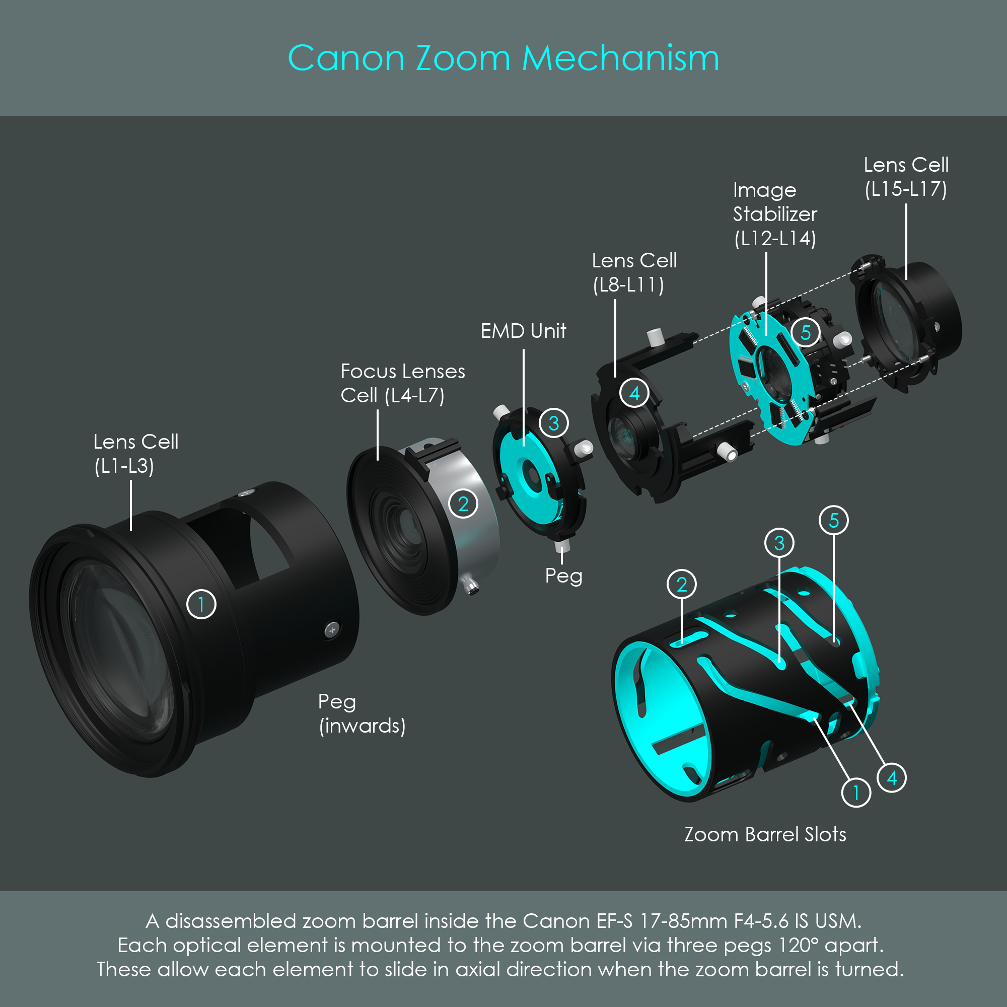
An exploded view of the same zoom mechanism reveals some more details. The zoom barrels do not only hold lens cells with optical glass elements but also the electromagnetic diaphragm (EMD) unit that forms the aperture, and the image stabilizer (IS) unit of the lens. Each part is suspended from the zoom barrels via small nylon pegs, and turning the helical slot barrel while the other one remains stationary slides the units along the optical axis.
Closer inspection of the mechanism shows that: