In the production of photographic lenses it has become a common procedure to apply anti-reflective coatings to all installed lens elements. Without these coatings, lenses with larger numbers of glass elements would not be functional. This chapter explains why uncoated lens elements are problematic, how anti-reflective coatings work, how they are applied to lenses, and how Canon has already adopted nano technology for the application of next-generation coatings.
Photographic lenses from the early 20th century usually had just a few glass lens elements. The Zeiss Tessar design from 1902, for example, had four lens elements, which was a very common number of elements back then. In order to reduce optical aberrations it was often required to increase the number of lens elements. Adding lens elements to a photographic lens assembly, however, often resulted in lower contrast of the image because of all the light reflection occurring at each air-glass interface. For that reason, somewhere around six lens elements was roughly the upper limit at that time.
A very simple form of anti-reflective coating was discovered at the end of the 19th century. The optical glasses available at that time tended to develop a tarnish on their surfaces with age due to chemical reactions with the environment. In 1886, it was observed by English physicist Lord Rayleigh that older, slightly tarnished lenses transmitted more light than newly produced, freshly polished lens elements. Rayleigh's research showed that the tarnish had actually formed an additional layer of material that had a refractive index somewhere between the index of air and the index of the optical glass. For that reason, incident light would not pass through a single and very sudden transition between air and glass but rather pass through two transitions with smaller changes in refractive indices. Naturally, two interfaces also resulted in two reflections. The surprising fact in Rayleigh's observation was, however, that the total of the two reflections is smaller than the single reflection that had occurred at the single air-glass interface of an untarnished lens. Interestingly, it had already been described theoretically by French physicist Augustin Jean Fresnel in 1818 that an additional thin layer of low index material would reduce the reflectivity of a lens surface.
In 1891, English optical designer Harold Dennis Taylor published a book about similar observations he had made on tarnished lenses. From about 1904, Taylor developed and patented techniques using chemical baths to artificially produce the tarnish on lens surfaces. These chemical treatments were the groundwork for contemporary lens coating techniques. In 1935, an employee at German optics company Zeiss, Oleksandr Smakula, improved and patented newer technologies for the application of anti-reflective lens coatings.
The significance of this technology has not only become clear in the field of photography but has also been widely recognized across all optical areas:
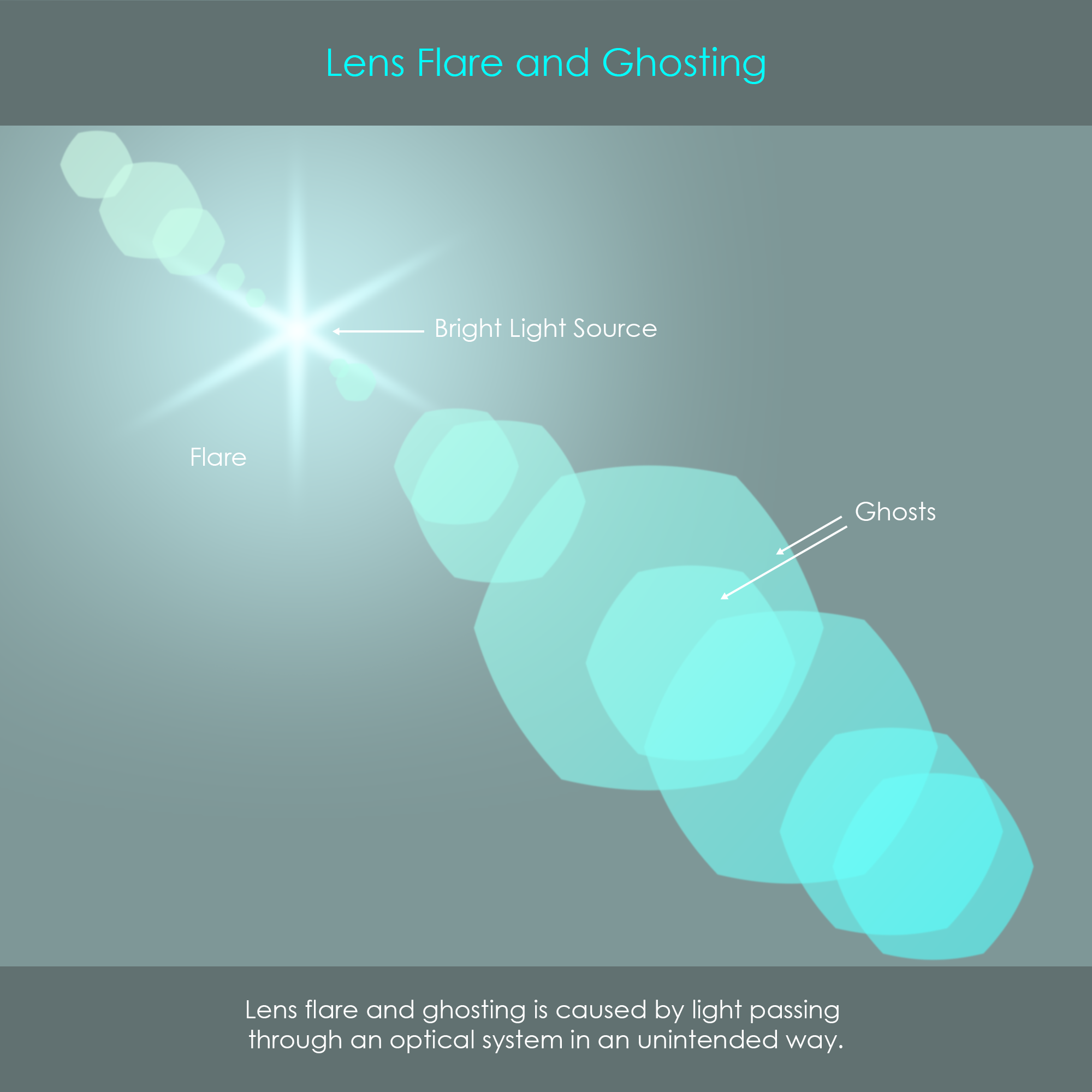
Camera lenses with no anti-reflection coating may exhibit different forms of veiling flare and ghosting. These effects are caused by the presence of stray light that passes through the optical system in ways that were not intended in the design of the lens.
Veiling Flare: This is an unwanted effect that produces an overlay of light around very bright light sources and noticeably reduces contrast and color reproduction in that area. It may be caused by smears or other contaminants on lens elements but also from light rays reflecting off from inner barrel parts.
Ghosting: Another unwanted effect that typically occurs in the form of aperture-shaped bright overlays. Ghosts are caused by unintended interreflections of light rays between two arbitrary lens surfaces. These light rays eventually end up on the camera's image sensor in a defocused configuration and in a different position.
Flare and ghosting become most noticeable in dark scenes when a small number of very bright lights is present in the field of view, or when the lens is pointed directly at the sun. Veiling flare and ghosting are not considered optical aberrations.
For a ghost image to occur, light must reflect from lens surfaces an even number of times, so there must be at least two lens surfaces involved. In this context, optical designers sometimes speak of surface-pair reflections. Photographic or videographic zoom lenses typically have up to 100 possible surface-pair combinations and almost all of them could cause unwanted interreflections, depending on angles and intensities of incident light rays. This can cause numerous ghosting shapes at the same time. As a rule of thumb, the higher the intensity of a light source is, the more ghost images can show up in the final image. The use of anti-reflective coatings is the most effective way to reduce flare and ghosting, although these may never be completely eliminated. Lens ghosts can either be in focus or out of focus.
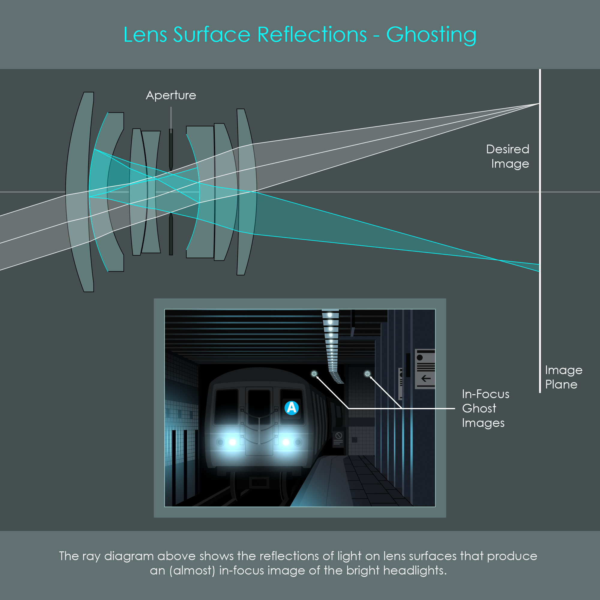
If a ghost shape produced by a surface-pair reflection is focused on the image plane, the ghost looks like the source. An in-focus ghost image is usually a coincidence because any surface-pair reflection causes the path of light to be completely random. The in-focus ghost image is formed away from the desired image position, and therefore appears to be completely out of context, hence the name ghost image. The illustration about ghosting shows one out of many other possible double-reflection sequences (cyan) for this camera lens compared to the desired path of light (white).
The most common form of ghost image are larger out-of-focus shapes. These are again caused by surface-pair reflections but do not form a focused image on the camera's image sensor. Out-of-focus ghost images can be perfectly circular, aperture-shaped, sickle-shaped, or show combinations thereof.
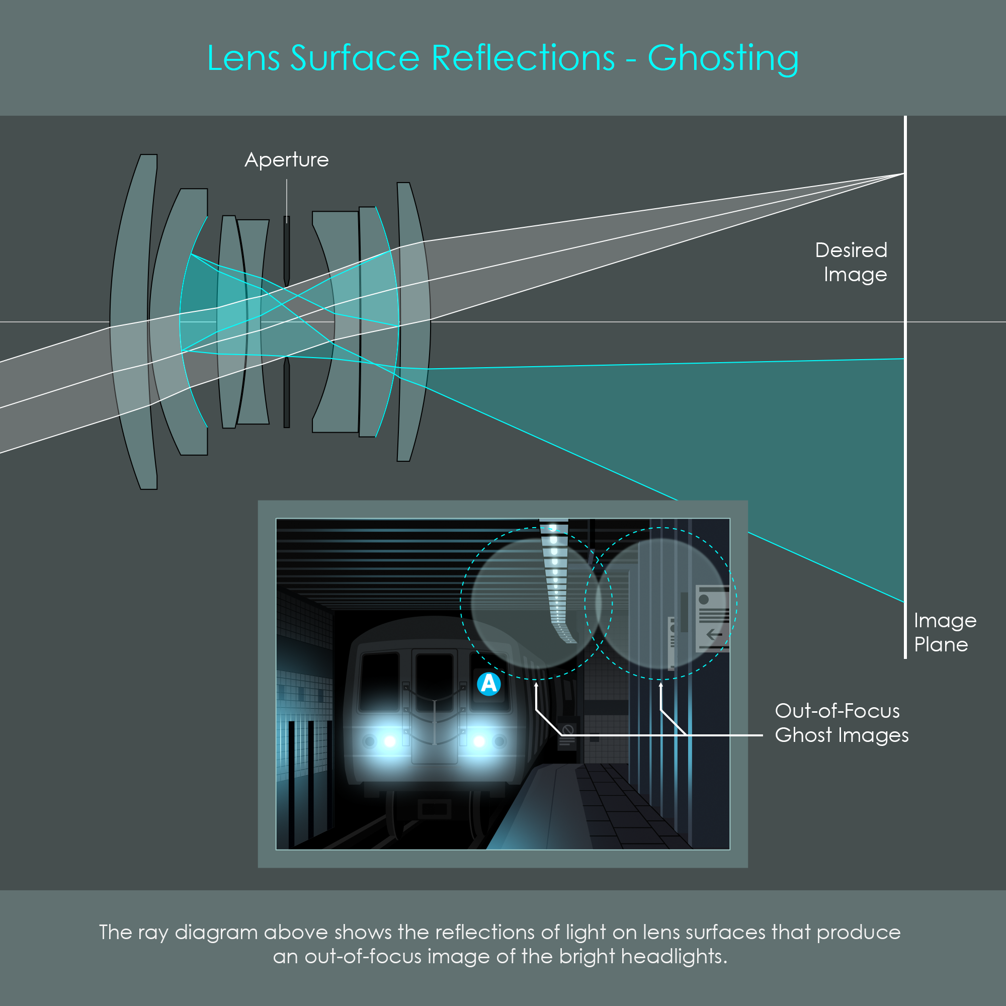
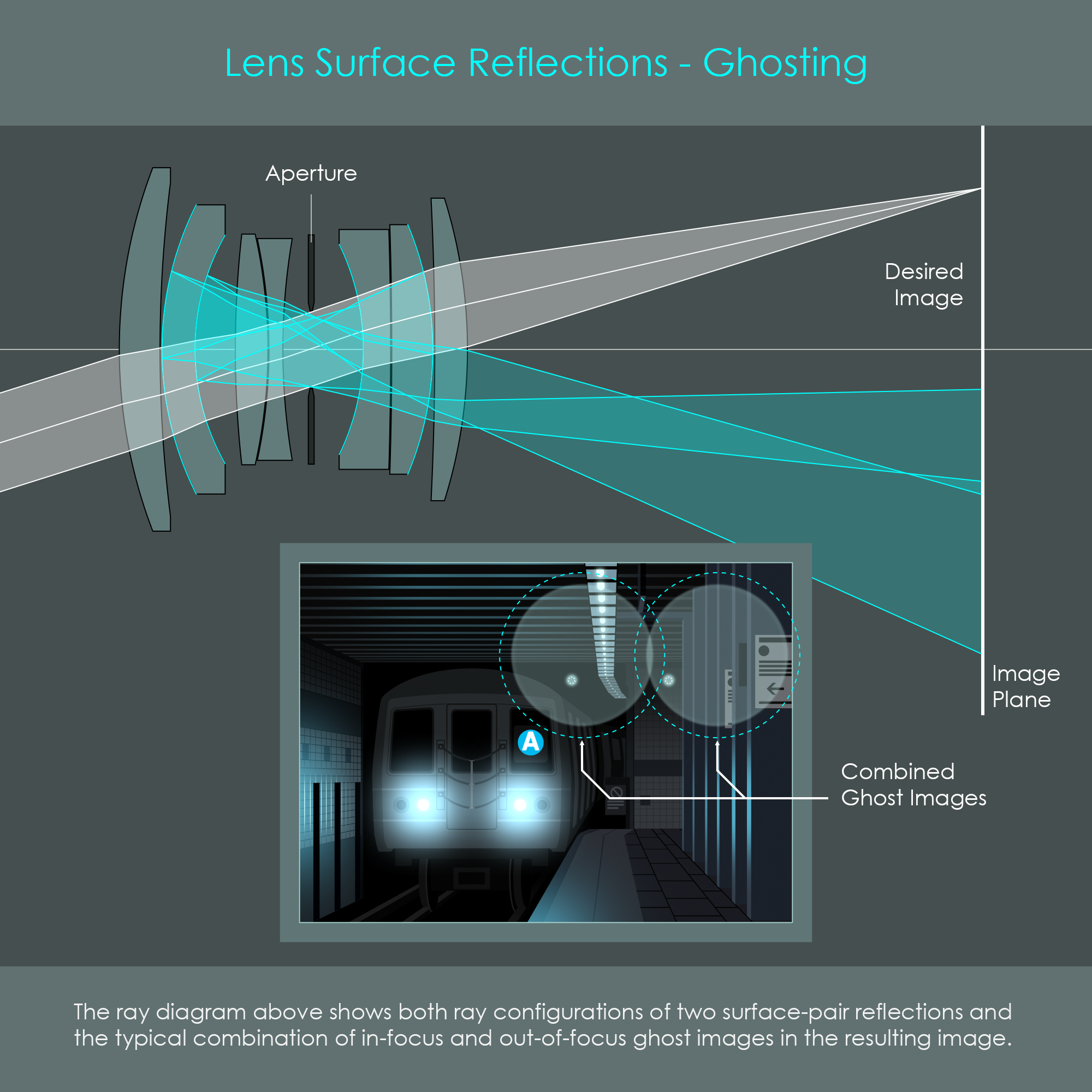
The illustration shows the desired path of light (white) versus the combination of two unintended paths of light (cyan) which form one in-focus ghost image and one out-of-focus ghost image.
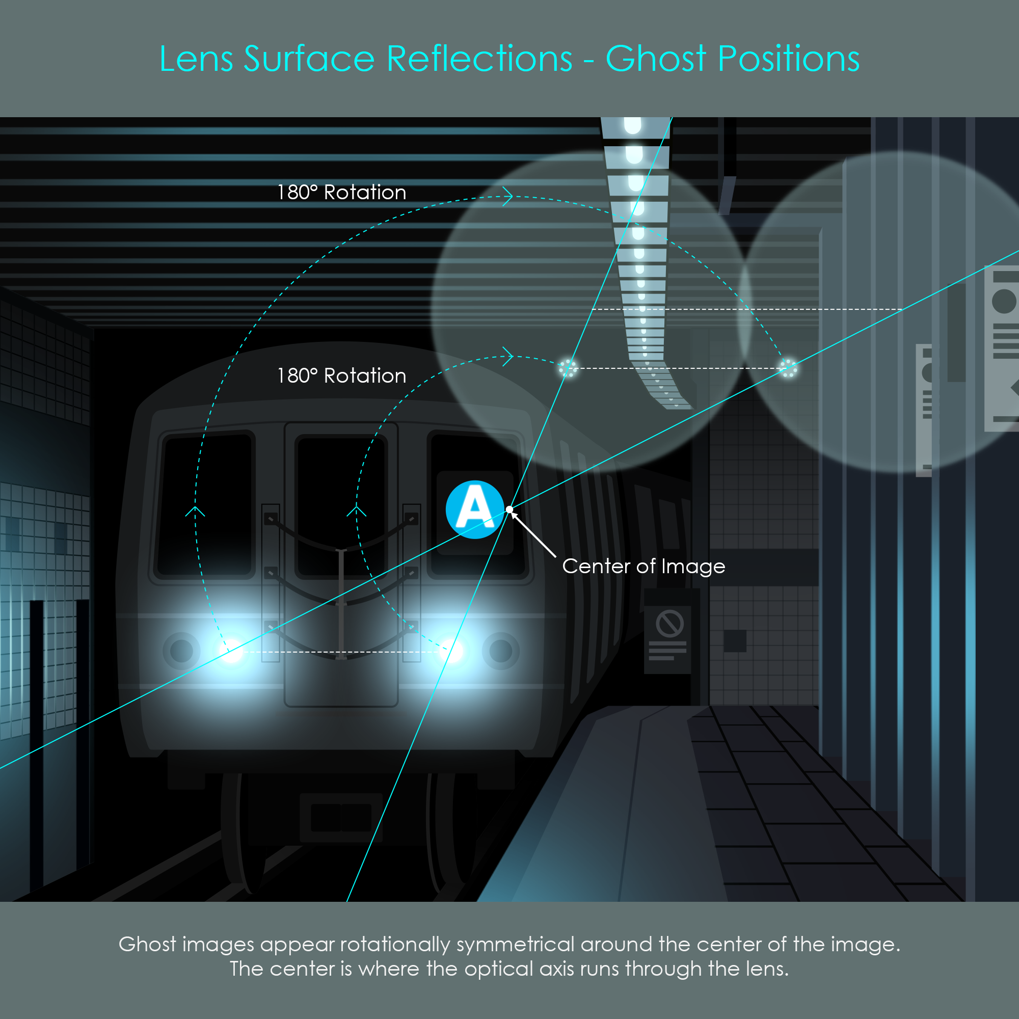
The positions of ghost images can be found rotationally symmetrical opposite to the original light source. In-focus ghosts appears as clear but darker copies of the headlights whereas out-of-focus ghosts appear as larger transparent discs.
An even greater problem than veiling flare and ghosting is the loss of light occurring at uncoated glass surfaces. Light that is reflected from lens surfaces an uneven number of times leaves the optical system and does not contribute to the final image.
The reflectance of uncoated optical glasses depends on the material used and varies between 4% and 10% at each surface in case of vertical incidence of light. This means that light transmission is only between 90% and 96% at each surface. Reflectance even increases with the angle of incidence, further reducing transmission. The following table summarizes some optical materials and their reflectivities.
| Optical Glass | Refractive Index | Reflectance [%] |
|---|---|---|
| CaF2 | 1.44 | 3.3 |
| BK7 | 1.52 | 4.3 |
| SF5 | 1.67 | 6.3 |
| LAF7 | 1.75 | 7.4 |
| LASF46A | 1.9 | 9.6 |
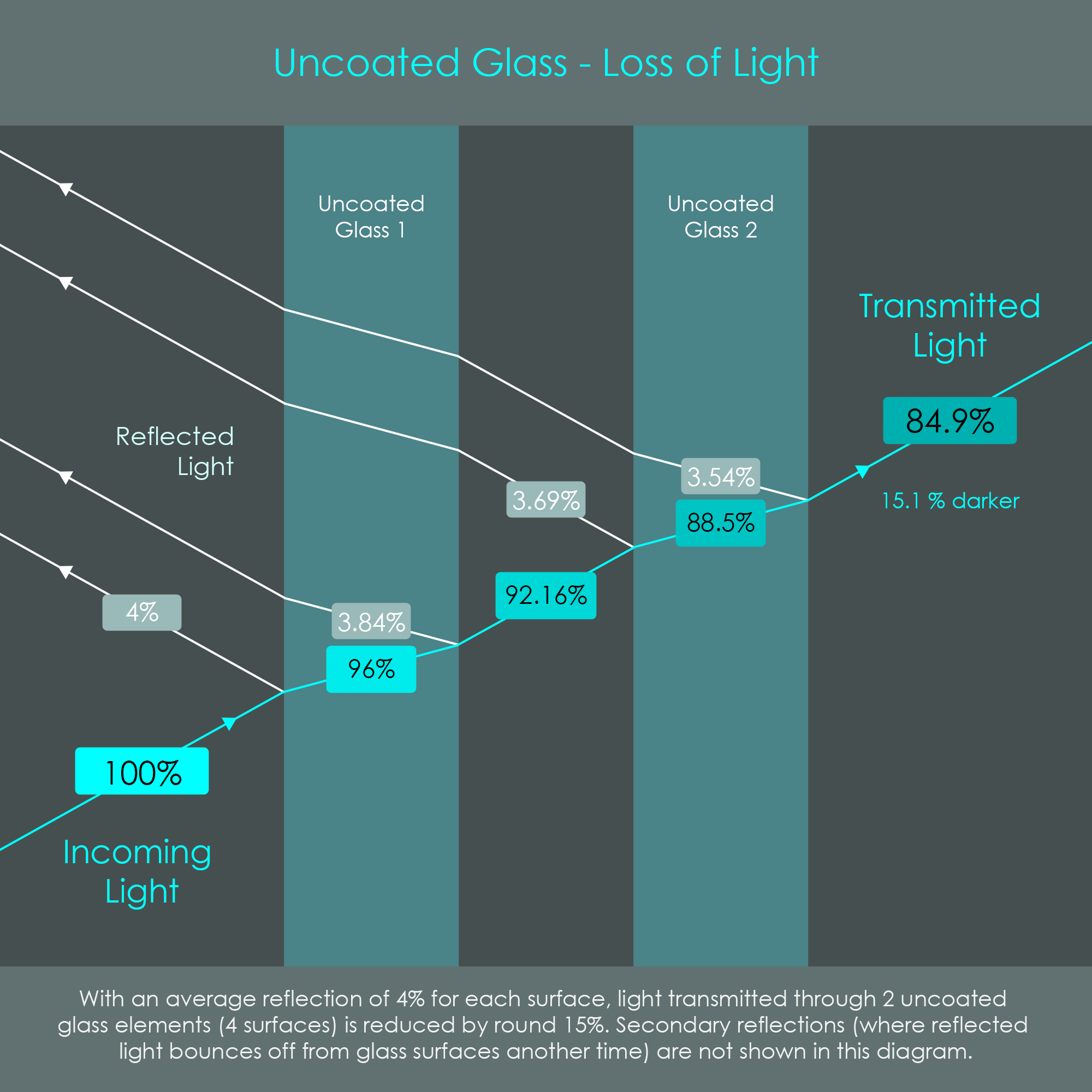
A very commonly used optical material is BK7 glass. The reflectance of uncoated BK7 glass is approximately 4% at each surface. As every lens element has a front and a rear surface, this means that the overall loss of light from passing through one lens element of BK7 glass is almost 8%.
The illustration demonstrates the loss of light that occurs on four surfaces of two glass elements of BK7 glass. Transmission through these two layers of glass (four surfaces) can be described as 0.964 = 0.849 = 84.9%. This means that total reflectance is 100% - 84.9% = 15.1%. With modern anti-reflective coatings, this total reflectance can be brought down to rd. 1%.
If this calculation was done for six lens elements (12 surfaces), which was roughly the maximum number of lens elements of early photographic lenses, transmission was 0.9612 = rd. 60%. In such a lens, rd. 40% of the light is reflected, making the image extremely dim. With all six lens elements coated, this total reflection can be brought down to rd. 10%.
This is the main reason why the application of anti-reflective coatings has become a standard practice in the fabrication of photographic lenses. Coatings are typically applied to all surfaces of lens elements that are exposed to air.
The principle of anti-reflective coatings can best be described using the wave theory of light. Many of the anti-reflective effects occur due to interactions between light waves and coating materials. Anti-reflective coatings do not only reduce reflections but, more importantly, increase transmission of light through glass elements.
An electromagnetic wave – such as light – consists of an alternating electric field and an alternating magnetic field perpendicular to each other. However, it is a common practice to draw only one of these components in illustrations to keep things two-dimensional. The alternation of the field is drawn as a sinusoidal wave that has peaks (crests) and valleys (troughs). This waveform repeats after 2π (360°). When the electromagnetic wave propagates, its peaks and valleys move parallel to the center line with time. Once it has propagated an exact wavelength's distance, the wave has completed one full cycle.

The phase of a sine wave – represented by the Greek letter ϕ – is a constant that indicates where the wave is in its cycle. In the sine wave illustration, the crest is currently at the 90° position. If another wave had the crest at the 270° position, these two waves had a phase difference of 180° or π. In a sine wave, the wavelength λ always corresponds to a phase difference of 2π.
Frequency describes how many cycles an electromagnetic wave performs in a given amount of time, typically within one second. The frequencies for visible light range from 400 THz (red light) to 790 THz (violet light). The unit THz stands for terahertz which is one trillion (1012) hertz, or one trillion wave cycles per second.
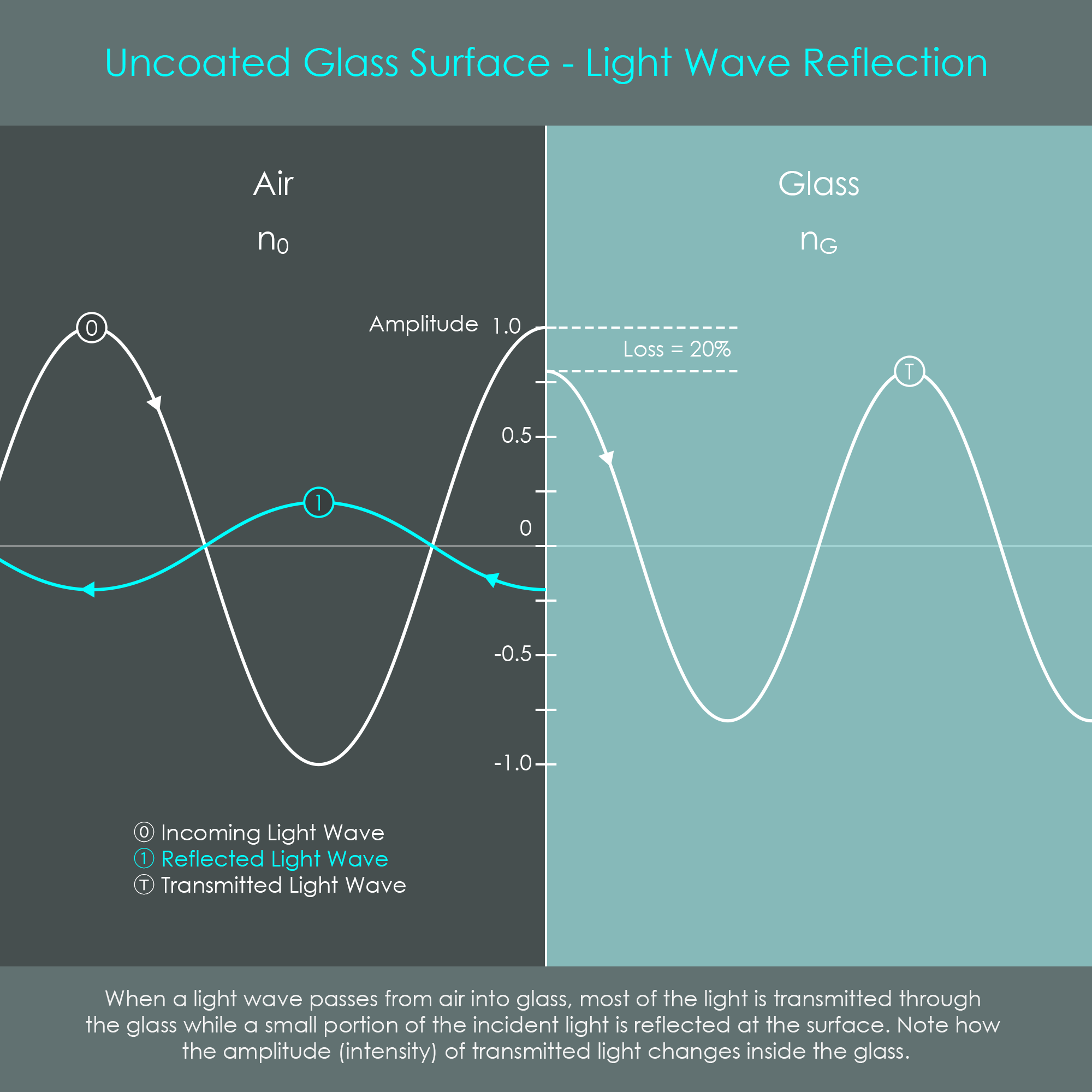
Whenever a ray of incident light passes from one substance into another – such as light traveling through air and entering glass – two major effects can be observed:
1. Change of Amplitude: At the interface between air and glass, some fraction of the light's initial energy is reflected back. As a result, the ray of light that is transmitted through the glass has a reduced amount of energy which means that it is darker than before. The intensity of light is indicated as the amplitude of a light wave. The illustration shows how a reflected wave is created at the interface and how the transmitted wave of light has a reduced amplitude resulting from the energy loss. Note that 20% is an exaggerated value as in reality the average reflectivity of optical glasses is around 7%.
The reflectance ratio of a surface is always relative to the intensity of the incident light. It varies from 0 (no reflection) to 1 (all incident light is reflected) and is typically expressed as a percentage (0% - 100%). Complementary to the reflectance is the transmission ratio which is also relative to the intensity of the incident light. Identically, it varies from 0 (no transmission) to 1 (all light is transmitted through the interface) and is equally expressed as a percentage (0% - 100%). If absorption and other possible effects are neglected, then the values of reflection and transmission added together always result in the value 1.
2. Change of Wavelength: As soon as a ray of light enters into another medium, its wavelength is changed. The reason therefore is that light travels at different velocities depending on the material. The higher the refractive index of a material, the lower the speed of light (c) inside that material and the smaller the distance that light travels over the same amount of time. However, the frequency of the light wave remains the same even in the denser material. So, in order for light to complete the same number of full wave cycles inside the denser material, the wavelength is shortened.
The factor at which the wavelength is decreased is the ratio between the speed of light in air (c0) and the speed of light in the denser material (cG).
As nG = c0⁄cG = λ0⁄λG the wavelength in a substance with nG can also be expressed by the formula λG = λ0⁄nG .
The optical path length (OPL) describes the travel distance of a light wave in measurements of wavelengths λ instead of using absolute distances. If a light ray of reference wavelength λ0 passes from air (n = 1) into a substance of n = 2, its wavelength λG is half the reference wavelength and it will perform twice the amount of wave cycles over the same distance. Therefore, the optical path length inside the medium has increased by a factor of 2.
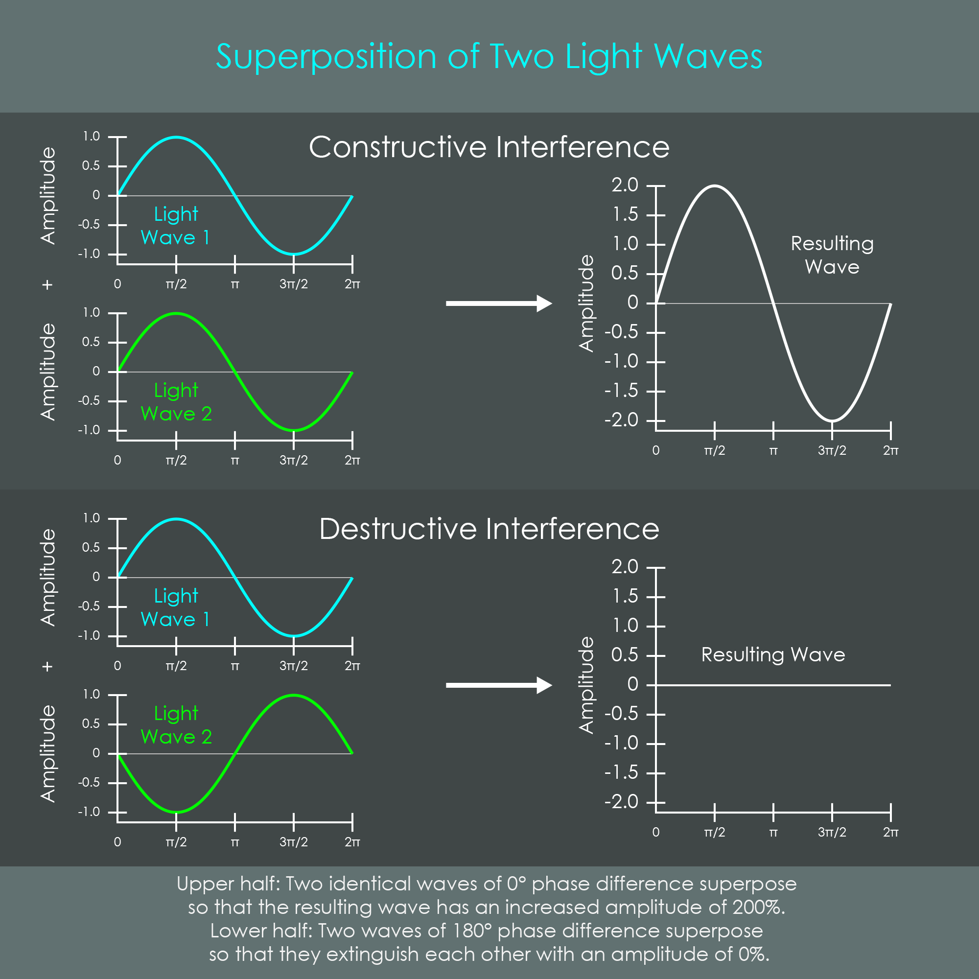
In the presence of two or more electromagnetic waves of the same frequency, the energy of these waves can interfere with each other so that their combined energy forms a resulting wave. The addition of these waves with each other is called superposition. The result is a sine wave again, however its exact waveform depends on the phase difference of these two waves. The two extreme types of wave superposition are constructive interference and destructive interference:
Anti-reflective coatings heavily rely on the principle of destructive interference of two or more light waves. The coatings are applied in such a way that they create conditions for reflected waves to cancel each other out.
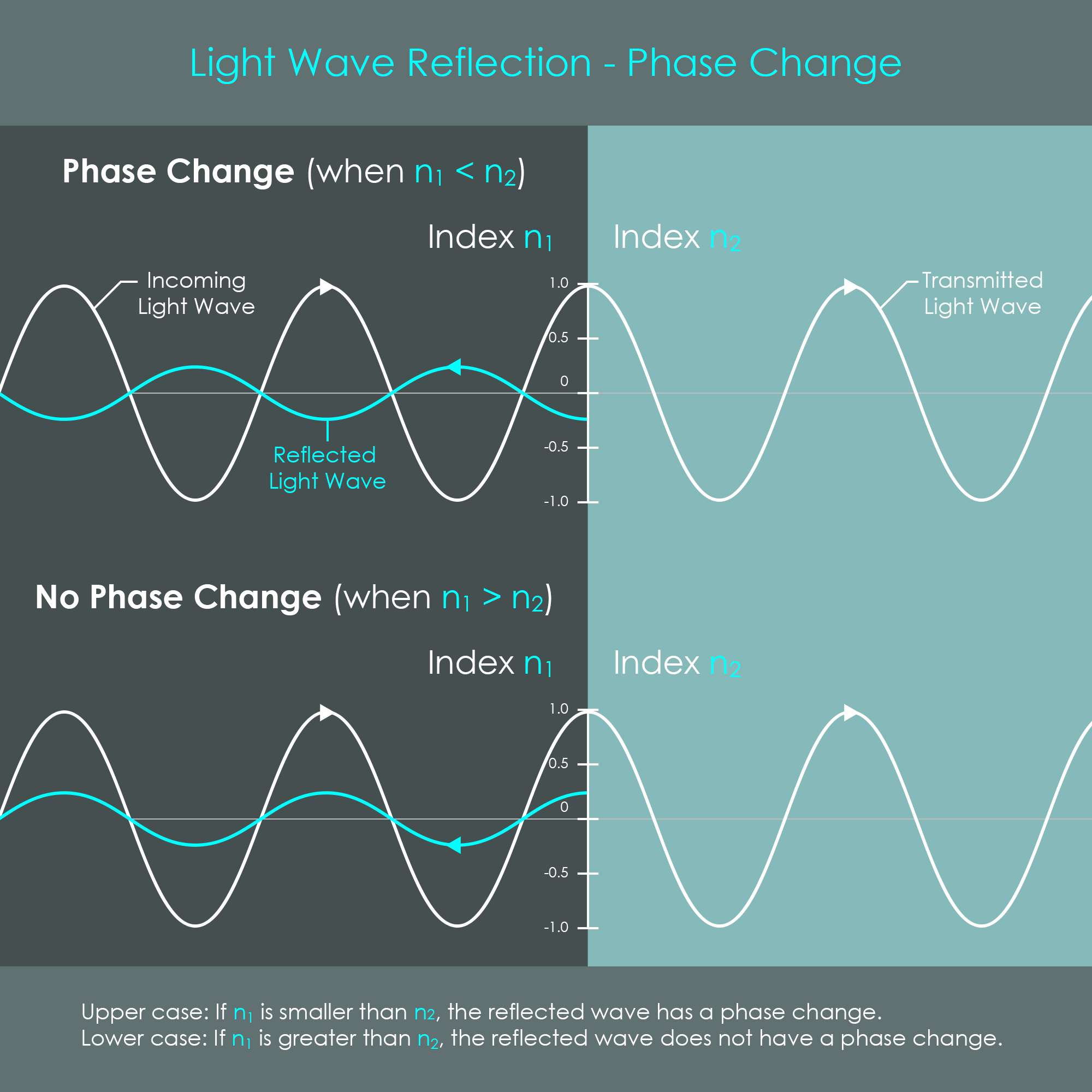
Another phenomenon that ensures the functionality of anti-reflective coatings is that light waves may change their waveform under certain conditions. This is often described as a phase change but what actually happens at the reflection is a reversal of polarity or reversal of amplitude. The name phase change originates from the fact that a light wave with a reversed polarity appears to be phase shifted by λ/2.
Interestingly, a polarity reversal only occurs with reflections at interfaces where the reflecting medium is denser than the medium where light is coming from (n1 < n2). Only in that case the resulting wave has a reversed polarity (upside down) and usually a smaller amplitude because only a fraction of light energy is reflected.
If light is reflected at an interface where the reflecting medium is thinner than the medium where light is coming from (n1 > n2), no polarity reversal occurs. However, the reflected wave usually has a smaller amplitude.
It is important for later explanations that if a polarity reversal occurs and the wave undergoes an additional phase change of λ/2 at the same time, the resulting light wave will appear as if nothing has happened. This is because an opposite polarity corresponds to a phase change of λ/2, and with an additional λ/2 the wave appears to be shifted one λ, not changing its phase.
It sounds surprising that an additional layer of material on a lens can increase light transmission. One might think that coating the lens surface would block some amount of light, but in fact it increases light transmission. The following chapter explains how this works.
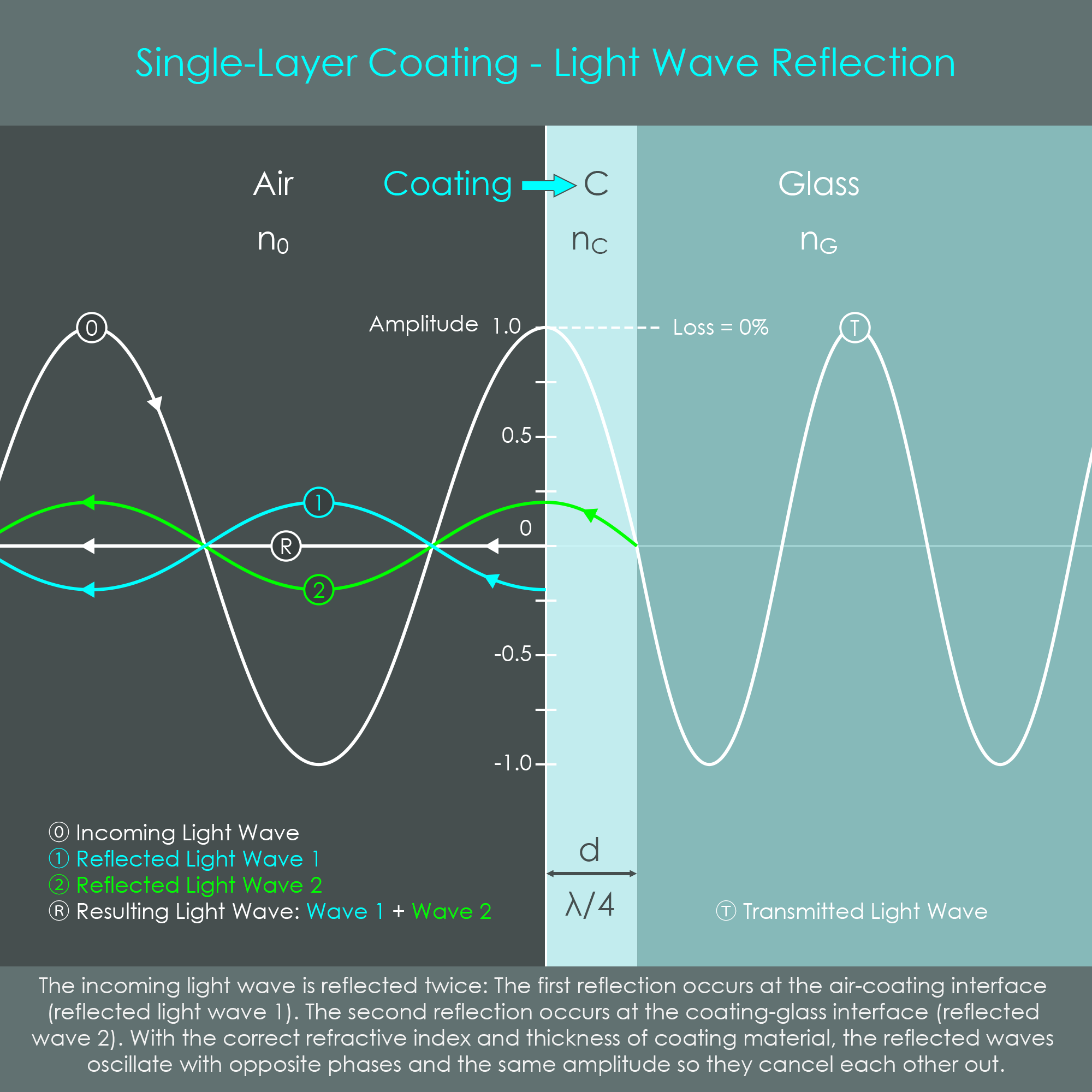
A single-layer coating applied to glass produces two reflected waves. The first reflection occurs when the incident wave passes the first interface (air-coating) and the second reflection occurs when the incident wave passes the second interface (coating-glass). Reflected wave 1 does a λ/2 phase change because nC has a higher value than n0. Reflected wave 2 similarly does a λ/2 phase change (nG has a higher value than nC) and in addition does a λ/2 distance shift because of the extra distance traveled. Therefore, reflected wave 2 appears to be unchanged in phase. Now the two reflected waves oscillate with opposite phases and therefore cancel each other out so that the amplitude of the reflected wave is 0%. Due to quantum mechanical effects of energy conservation the flux normally reflected must now be transmitted (Angus Macleod, 2000). In other words, the cancellation of reflected waves means that no energy is reflected back which in turn increases the energy transmitted.
This is the key principle how additional layers of material reduce reflections on glass surfaces and increase transmission.
For an anti-reflective coating to cause perfect destructive interference, some requirements must be fulfilled: Proper coating thickness and matching refractive indices.
The ideal thickness of a single-layer coating is λ/4. It is important that λ refers to the wavelength of light inside the coating material. As described earlier, the wavelength of incident light changes each time it moves from one substance to another, depending on the refractive indices. As a result, the reference wavelength of incident light (λ0) decreases by the factor nC when entering the coating. Therefore, the ideal thickness of a single-layer coating can be described using the formula d = λ0⁄4 nC .
For a reference wavelength of 550 nm and a coating material with an index of 1.38 the ideal coating thickness would be 100 nm.
If this thickness requirement is satisfied, destructive interference occurs because the optical path length for light in the coating layer is λ/2 (λ/4 front to back and λ/4 back to front). In optical engineering, the thickness is often specified as quarter wave optical thickness (QWOT) and the single-layer coatings are simply referred to as λ/4-coatings or quarter-wave coatings.
Not only the thickness but also refractive indices of the coating and glass must be aligned with each other so that they can induce mutual cancellation of the reflected waves. The choice of materials is a decisive factor in the design of an effective anti-reflective coating. The relation between refractive indices must be nC = √nG or similarly nG = nC².
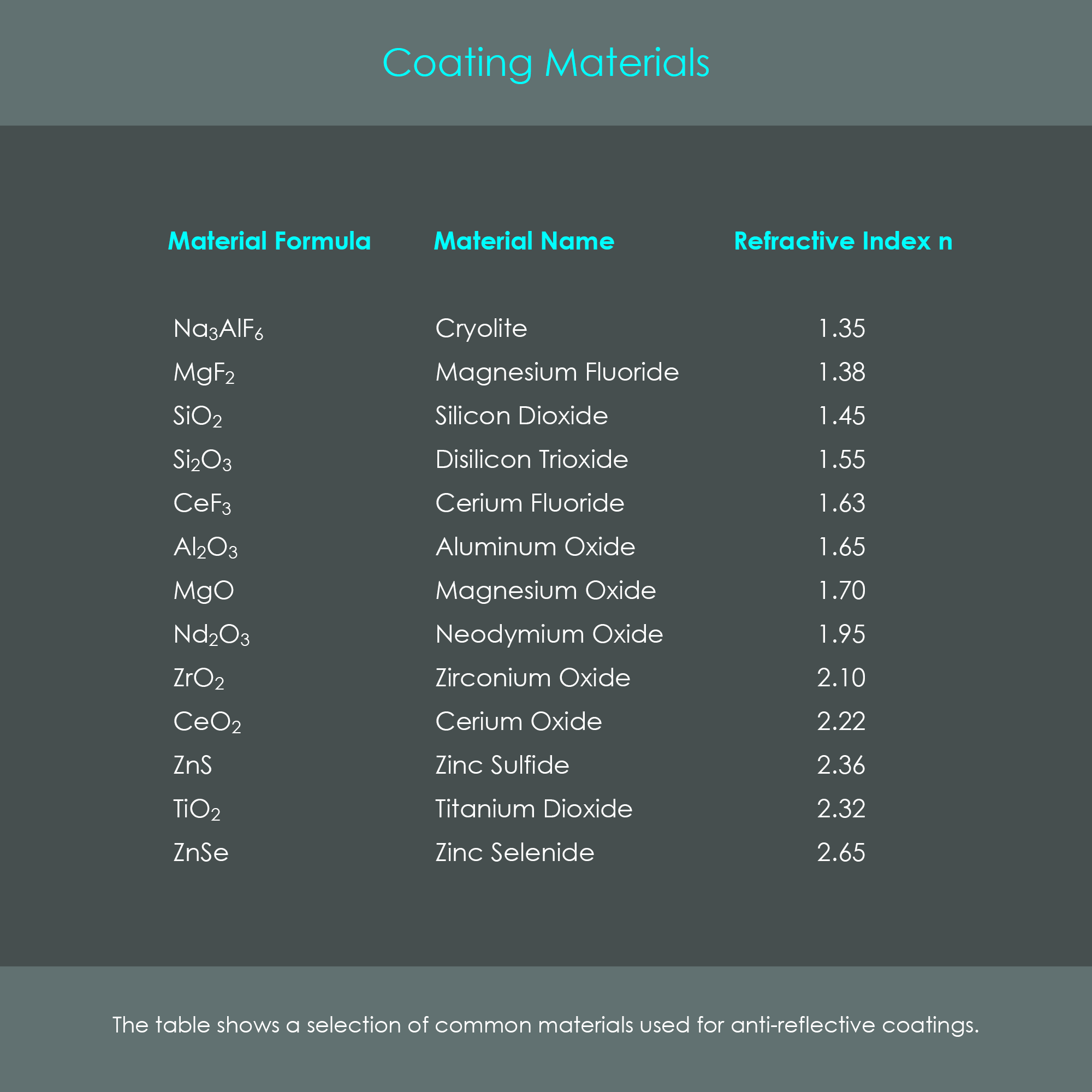
This shows that an anti-reflective coating is not a layer of material that acts independently but rather must be chosen depending on the glass used. If the relation is not according to the formula, the reflected waves are not cancelled out entirely. A coating material that is often used due to its robustness is magnesium fluoride (MgF2) with a refractive index of 1.38. Here are two examples that demonstrate how the effectiveness of a single-layer MgF2 coating changes with the selection of materials:
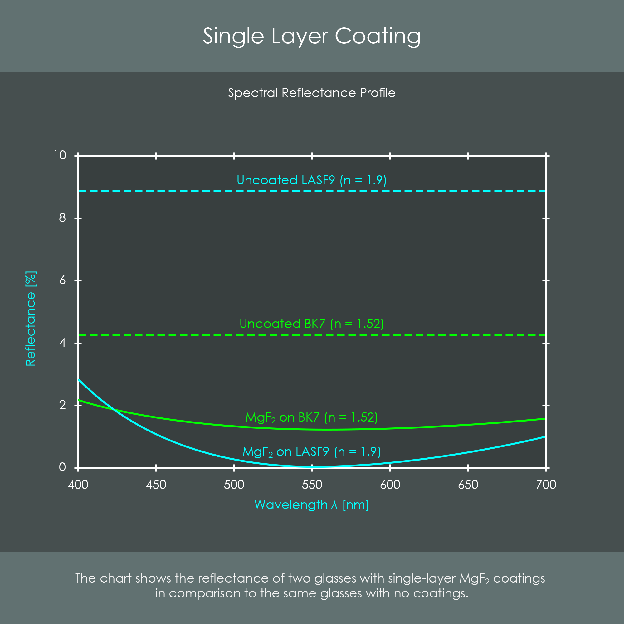
The diagram shows the spectral reflectance profiles of BK7 and LASF9 glasses with single-layer MgF2-coatings applied (solid lines) compared to the same glasses with no coatings (dashed lines). Note how the reflectivity becomes zero only for LASF9 glass because the wave-cancellation condition is met only with this combination of refractive indices (as explained above).
Every coating material is adjusted to the specific glass type, and the coating thickness is adjusted to a specific wavelength at which wave cancellation is supposed to occur with best results. This reference wavelength is typically chosen to be in the range of 510-550 nm as this is the center of the visible spectrum of light. Consequently, for other wavelengths the optical path differs from the value λ/2. For instance, the coating thickness is around 20% too long for blue light (λ = approx. 460 nm) and around 20% too short for red light (λ = approx. 660 nm). For this reason the reflected waves of red and blue light are not inversely phased by π (180°) and exhibit some larger reflectance values than green light. This is also visualized in the spectral reflectance profile as the values increase with distance from the reference wavelength. Therefore, single-layer coatings often look purple when seen from the front.
It was demonstrated that a quarter wave optical thickness is required for a single-layer coating to effectively work. An anti-reflective coating layer that is applied with an incorrect thickness will increase reflectivity for the reference wavelength λ0. Simultaneously, a change in thickness will lead to wave-cancellations of other wavelengths. In particular, a reduction in thickness will favor successful wave cancellation of shorter wavelengths while an increase in thickness will favor successful wave cancellation of longer wavelengths. The illustration on thickness deviation shows how the spectral reflectance profile is influenced by changes in coating thickness. Note that a relative thickness deviation of Δt = 20% corresponds to a thickness defect of only 20 nanometers.

The formulas that define the ideal preconditions for destructive interference are valid for light entering the surface at a 0° angle of incidence. For LASF9 glass with an MgF2 coating, for example, reflectance is almost zero at a 0° angle of incidence. Reflectance increases to rd. 1% when the angle of incident is 45°, and is at rd. 3% when the angle of incidence is 60°.
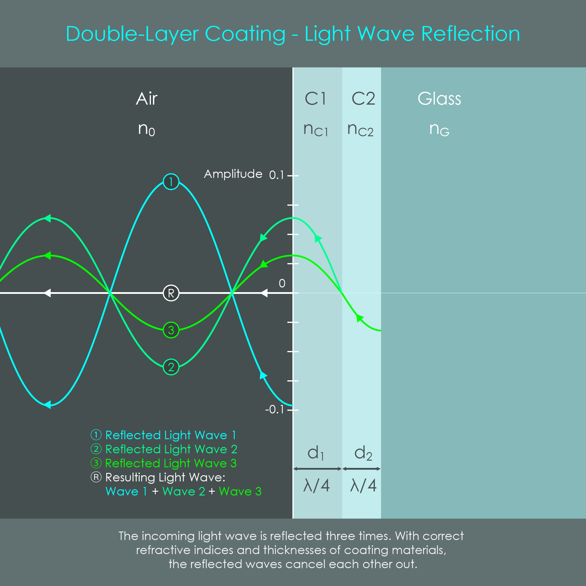
The design of an anti-reflective coating with two layers provides greater flexibility in the choice of materials to achieve the wave-cancelling condition. This double layer coating is also referred to as a thin-layer stack and the order in which refractive indices should be placed can be described as sHLa (substrate, high index, low index, and air). The illustration shows two coating layers on glass, and the materials are labeled air, C1 (coating 1), C2 (coating 2), and glass with refractive indices n0, nC1, nC2, and nG, respectively.
When light enters glass that is coated with two layers of coating material, three reflected waves 1, 2 and 3 are induced. Note that the illustration on double-layer coatings does not show the incoming light wave as its amplitude is off limits. That incident wave of light, although not shown, is at a positive peak (crest) at the first interface, it is zero at the interface between C1 and C2, and it is at a negative peak (trough) at the interface between C2 and glass. Reflected wave 1 does a λ/2 phase change because nC1 has a higher value than n0. Reflected wave 2 does a λ/2 phase change (nC2 has a higher value than nC1) and in addition does a λ/2 distance shift because of the extra distance traveled. Therefore, reflected wave 2 appears to be unchanged in phase. Finally, reflected wave 3 does not undergo a phase change because nG has a lower value than nC2, but does a full λ distance shift, not changing the apparent phase of this wave as well.
The amplitudes of reflected waves 2 and 3 add up via constructive interference to a wave with equal energy but inversely phased to reflected wave 1. This in turn causes all reflected waves to cancel each other out. Again, when all reflected light is eliminated, no light energy is reflected and therefore energy transmitted is increased.
These are the formulas that describe proper layer thickness and matching refractive indices for double-layer coatings:
A common way to design a double-layer coating is to apply two layers with different refractive indices with each having a thickness of λ0/4. Again, this thickness refers to a fourth of the wavelength that light has inside the coating material, and therefore the two layers typically do not have an identical absolute thickness. Note how in the illustration d2 is smaller than d1 because C2 is usually a higher index material than C1 (sHLa-rule). The relation at which both layers yield the same optical path length can be expressed as nC1 × d1 = nC2 × d2 = λ04. A double-layer coating using this combination of layer thicknesses is called a λ/4-λ/4-coating.
With a λ/4-λ/4-coating, full wave-cancellation for the reference wavelength λ0 occurs only if the following requirement is satisfied:
nC2⁄nC1 = √nG .
As a consequence from this relation, the necessary value √nG for low refractive index glasses, such as √1.52 = 1.23 for BK7 glass, can now be obtained by adjusting the ratio of the refractive indices nC2⁄nC1 of the layers. Two examples that show suitable combinations of λ/4-λ/4-coating materials on BK7 glass:
Again, a full cancellation of reflected wave intensity to almost zero can only be obtained for a certain reference wavelength λ0. Other wavelengths may perform worse than with a single layer coating. In addition, full cancellation can only be achieved for a zero angle of incidence. For other angles, the effectiveness of the coating decreases.
Another approach to structure the layers is to enlarge the λ/4-layer that is in direct contact with the glass surface to a λ/2-layer. The result is called a λ/4-λ/2-coating. The λ/2-thickness of C2 allows the wave to complete a full wave cycle of the reference wavelength once reflected back. For that reason, the wave reflected at the glass interface (reflected wave 3) is inversely phased with the wave reflected at the interface between C1 and C2 (reflected wave 2). Therefore, the reflected waves do not cancel each other out but form a resulting wave with an amplitude that is identical to that of a single-layer (λ/4) coating with a layer of MgF2 coating on BK7 glass. The advantage of a λ/4-λ/2-coating, however, is that the λ/2-coating lowers the reflectance for the red and blue wavelengths of light, as long as the index of refraction nC2 is larger than nG.
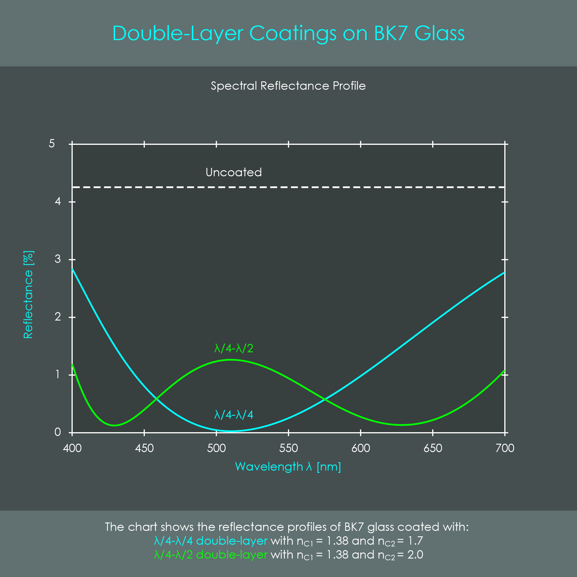
The illustration shows two spectral reflectance profiles of double-layer coatings on BK7 glass. The λ/4-λ/4-coating creates a typical V-shape where the tip of the V is zero at the reference wavelength. The λ/4-λ/2-coating, by contrast, creates a W-shape. For these reasons, λ/4-λ/4-coatings and λ/4-λ/2-coatings are also called V-coatings and W-coatings, respectively.
As the profile of the λ/4-λ/2-coating shows an increased reflectance in the center area, such a coating looks greenish when seen from the front.
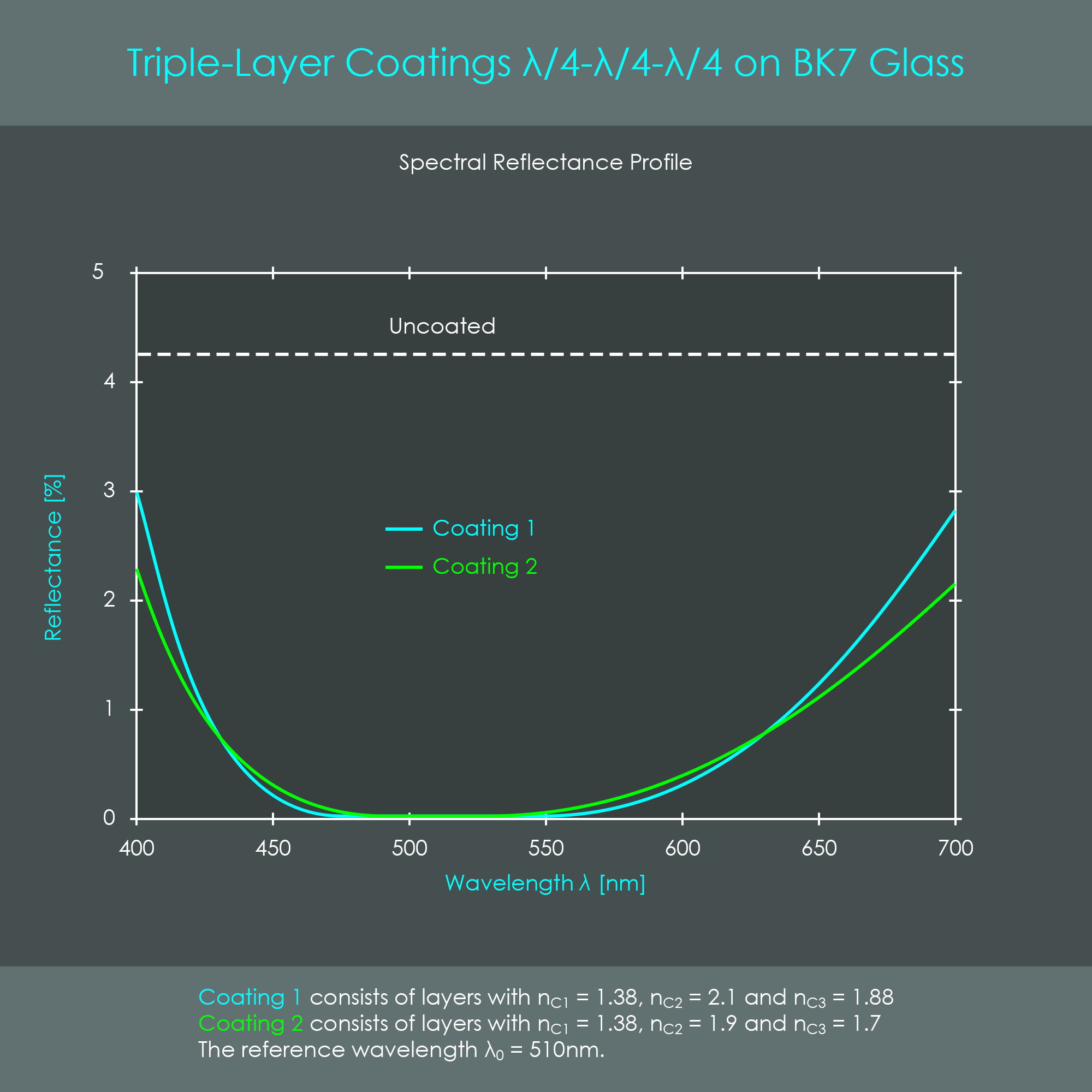
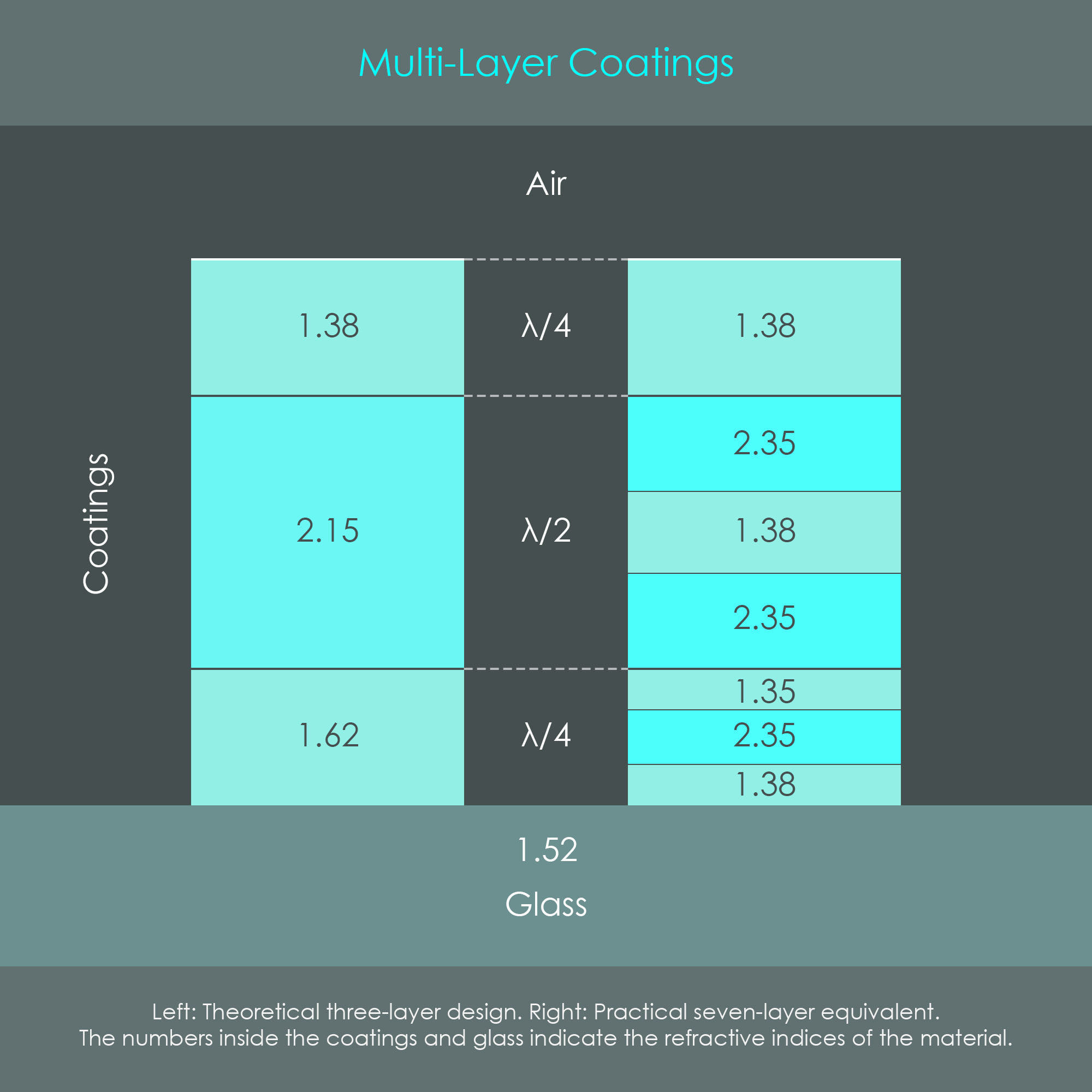
The reflectance of double-layer coatings can be reduced even further by adding more layers. With an additional coating layer, there are even more possible combinations of thicknesses and materials compared to previously shown designs. Two types of three-layer coatings commonly used are λ/4-λ/4-λ/4-coatings and λ/4-λ/2-λ/4-coatings.
For a λ/4-λ/4-λ/4-coating, the wave-cancellation condition occurs for λ0 if the following condition is satisfied: n1 × n3⁄n2 = √nG . For a λ/4-λ/2-λ/4-coating, the condition is n3⁄n1 = √nG . This is the same relation as for the λ/4-λ/4 double-layer coating. However, the added layer with a thickness of λ/2 effectively broadens the spectral reflectance profile.
Naturally, when either condition (coating thickness or relation between refractive indices) is violated, the resulting reflected wave is not entirely cancelled out, making the coating less effective. Full cancellation of reflected wave intensity to almost zero can only be achieved for a certain reference wavelength λ0 and for a zero angle of incidence.
The following two illustrations show triple-layer coatings on BK7 glass. The first diagram compares the spectral reflectivity profiles of two different λ/4-λ/4-λ/4-coatings.
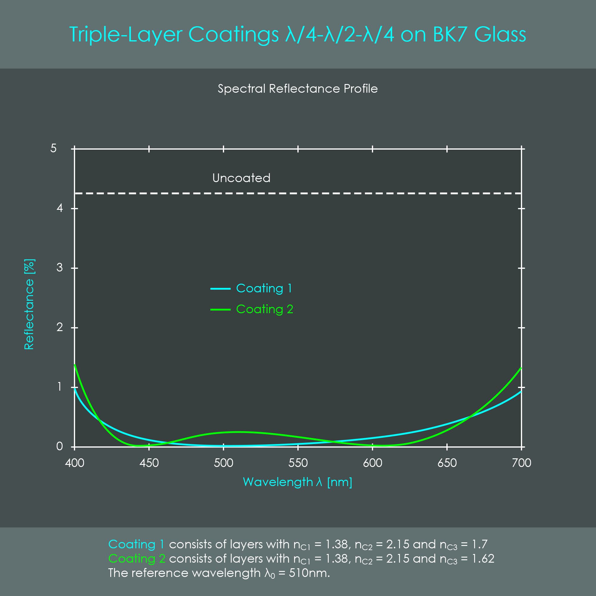
The second diagram compares the spectral reflectivity profiles of two λ/4-λ/2-λ/4-coatings.
The diagram shows how effectively these λ/4-λ/2-λ/4-coatings are reducing reflectivity over a wide range of wavelengths. Coating 2 is able to reduce two wavelengths to zero and exhibits an acceptably small level of reflectivity for the reference wavelength (green light). This in turn means that transmission of these two wavelengths is at 100% and close to 100% for the reference wavelength. Due to this excellent coating performance λ/4-λ/2-λ/4-coatings have become a reliable standard in the optimization of photographic lenses.
As not all refractive indices can always be selected to match the theoretical design (with the formulas), even more than 3 layers are applied in practice. Values 2.15 and 1.62 are theoretical optimums.. However, there is no material that has this RI - stacks must be built.
In addition to performing an antireflection function, coatings often also act as protection against dirt, water or ultraviolet radiation, and they can regulate the penetration of infrared heat radiation.
Lens manufacturers can choose between different techniques for the application of anti-reflective coatings. Two frequently used thin-film technologies are called plasma sputtering and vapor deposition coating. The former is more applicable for special cases and low production quantities, and is therefore not considered further. The latter is well suitable for high-volume batch production, and is explained below.
This technology is used to evenly deposit a coating material on the surface of lens elements. Uncoated lens blanks – in this context called substrate – are placed inside a substrate holder or substrate dome located on the upper side of a vacuum chamber. The solid coating material – called the evaporation source – is placed in a water-cooled crucible located at the lower part of the device. The coating process is started by sealing the chamber and evacuating the air. This is done to prevent any particles contained in the air to mix with the coating material. Once a vacuum has been established, the coating material is evaporated and the substrate holder is rotated to ensure consistent coating results.
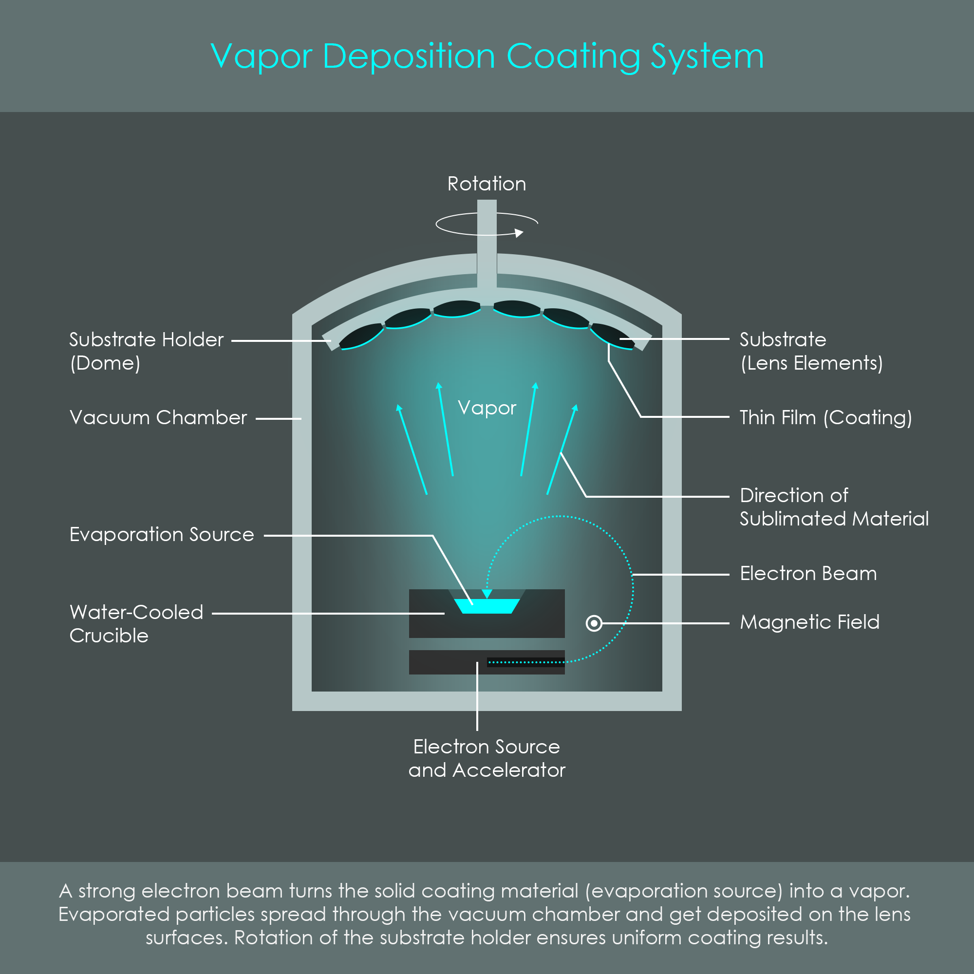
The evaporation source, a block of magnesium fluoride (MgF2) for example, is heated via high energy electrons in the form of an intense beam. Electrons are emitted from a glowing filament and these are accelerated by an electric field. As a glowing filament not only emits electrons but might also evaporate small quantities of its own material, the electron source is located out of sight from where the intended evaporation takes place. For the electron beam to reach the evaporation source, it is pulled around to the surface by a magnetic field. During the evaporation process, an energy in the range of 10 kilowatts is delivered upon impact with the coating material, enough to directly transform the solid state of the source into a gaseous state, called sublimation. The hot vapor that is created then spreads throughout the chamber, and is deposited on the lens surfaces.
Once the deposited material cools down, it solidifies on the lens surfaces. The chamber is filled with air again, and opened to remove the coated lens elements. Note that this coating process is repeated for the other surfaces of lens elements, and might be repeated several times with different evaporants in order to create multi-layer coatings.
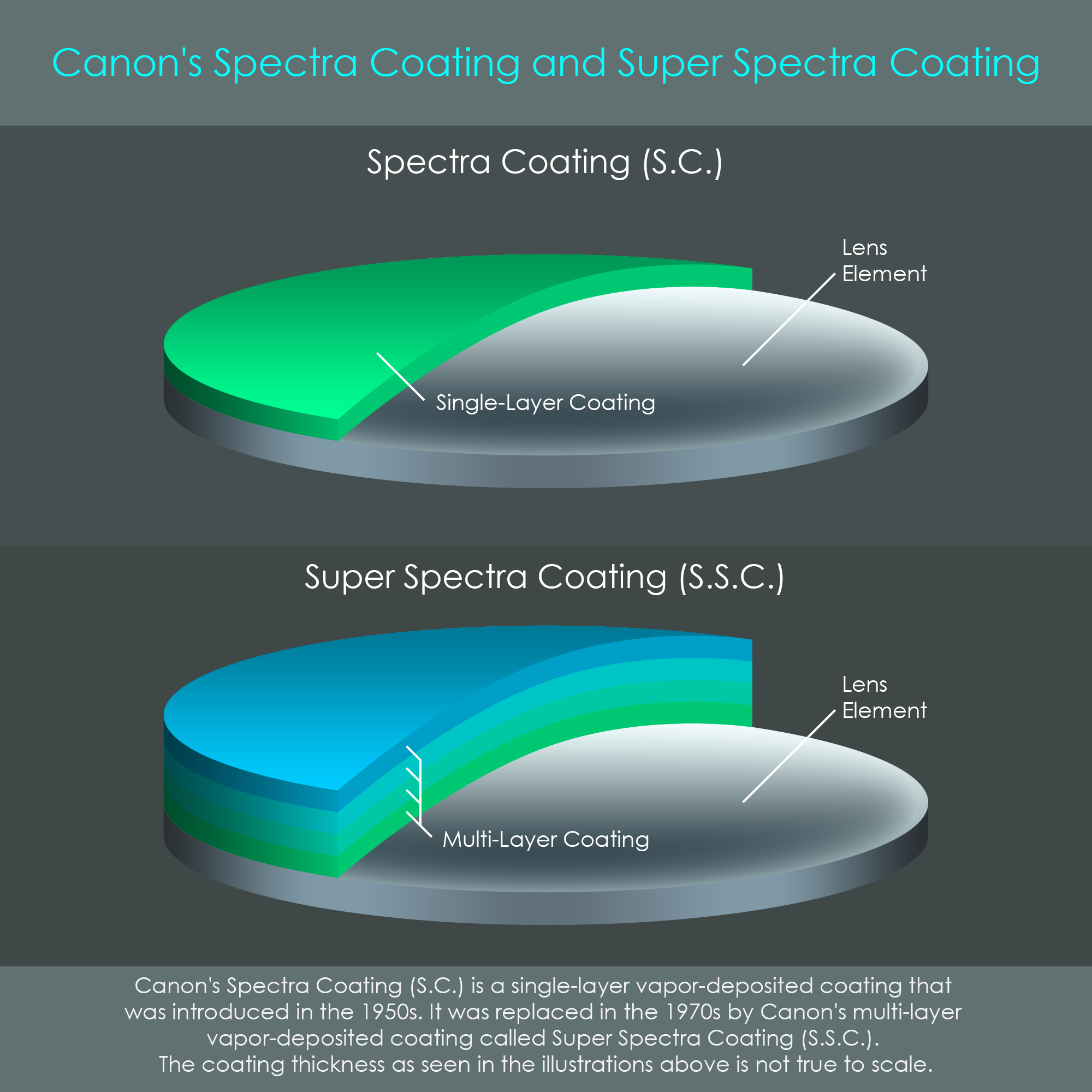
Spectra Coating (S.C.) is the name of Canon's first anti-reflective coating that was first introduced in the 1950s. The rising popularity of color photography has increased the needs of high performance lenses with excellent light transmission. To satisfy the needs of customers back then, Canon has used a single-layer coating to improve image quality. Unfortunately, with the Spectra Coating, reflections could only be reduced for one wavelength, leaving slight color tints in the photos.
In the 1970s, color balance of coated lenses was greatly improved by the introduction of multi-layer coatings. Canon called this solution their Super Spectra Coating (S.S.C.). The effectiveness of multi-layer coatings was described above, and with this technology Canon was able to meet much higher standards.
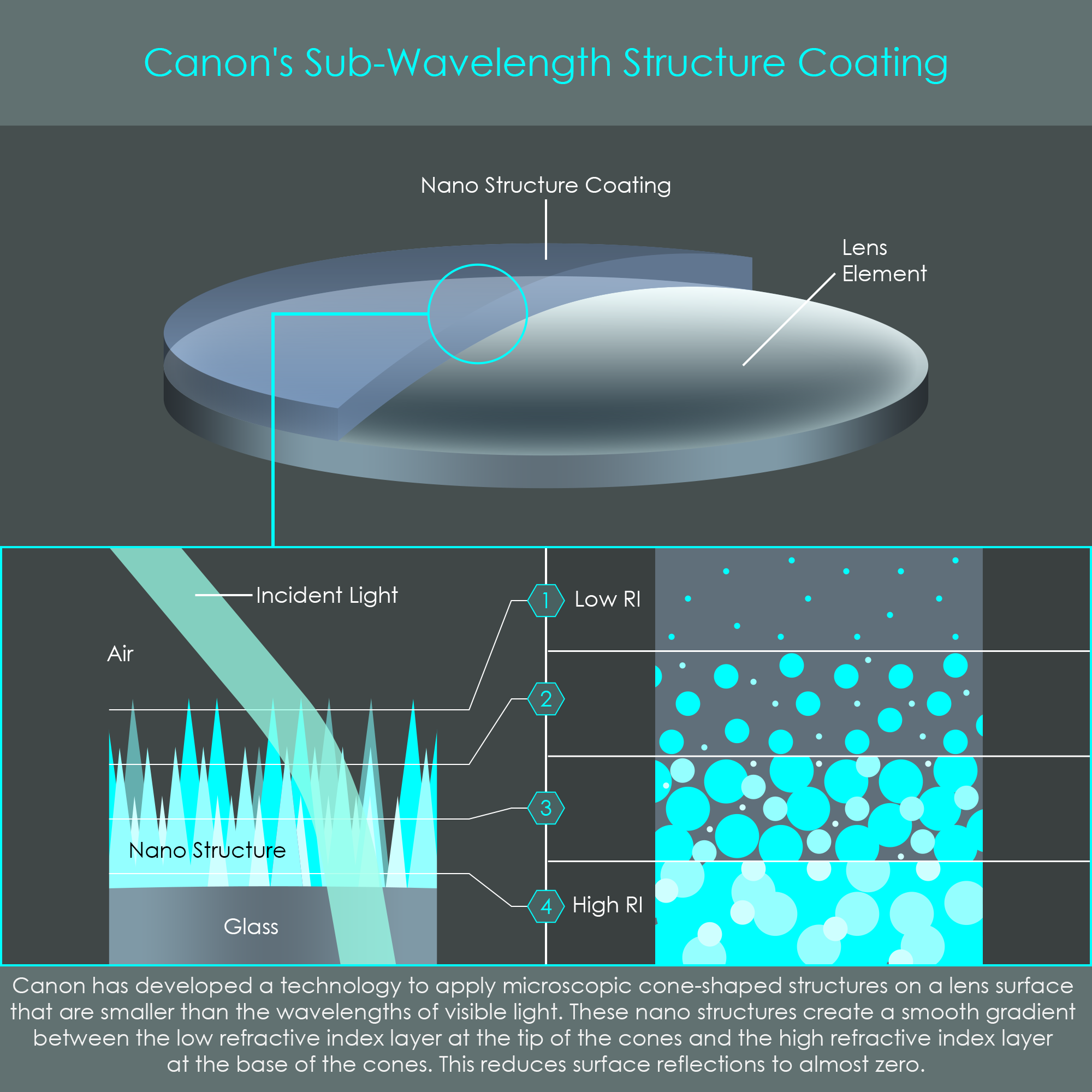
According to Lord Rayleigh's theories from the 19th century, an absolutely perfect anti-reflective coating would not rely on discrete layers but rather have a continuous gradient between the index of air and the index of glass. With the advent of new application technologies in the 2000s, lens manufacturers are increasingly using newer technologies to apply so-called graded-index (GRIN) anti-reflective coatings with a continuously varying index of refraction. It has been demonstrated that these are able to reduce reflections to zero even for a broad band of wavelengths and for various angles of incidence. Canon has developed two particularly effective types of GRIN coatings:
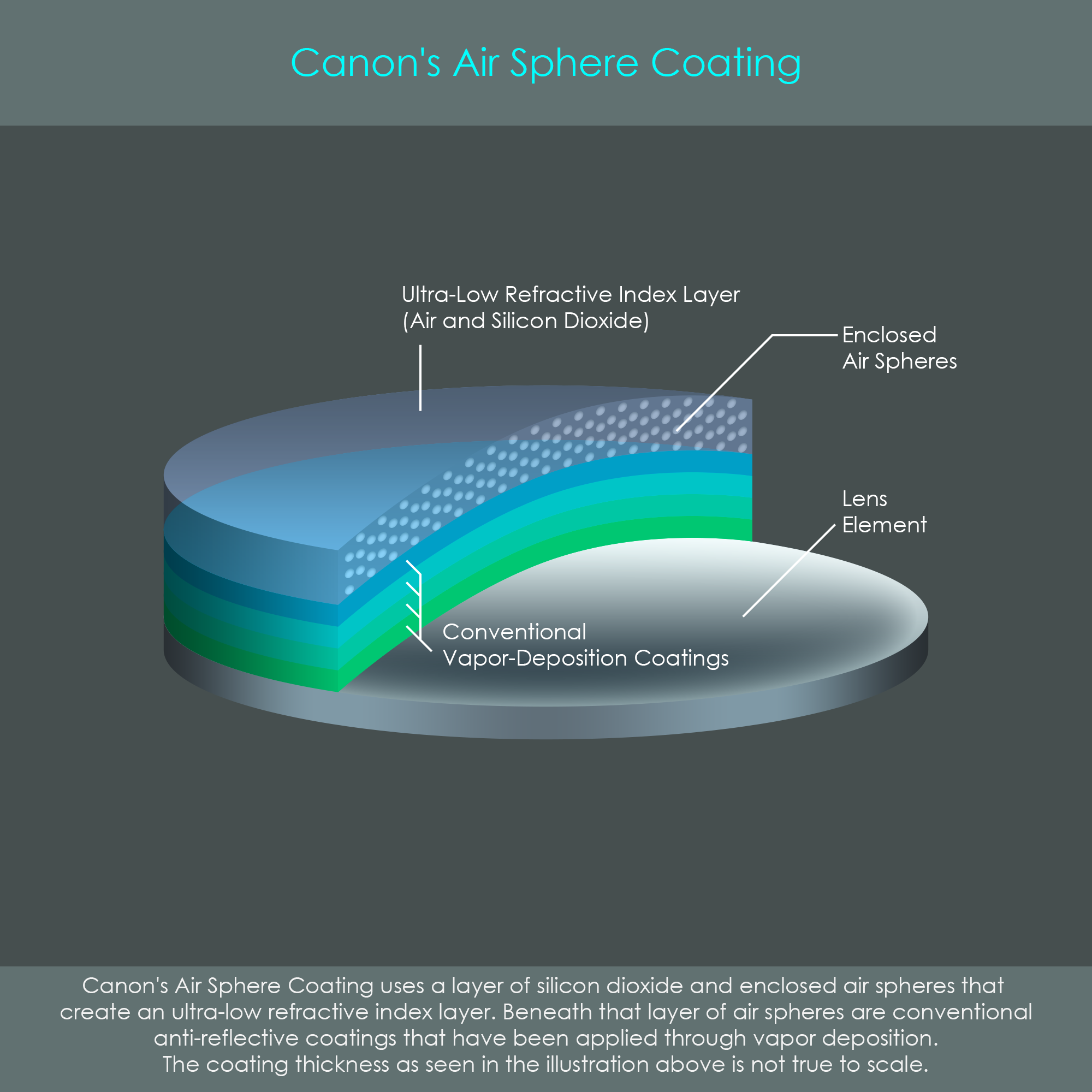
Canon's Air Sphere Coating (ASC) is a combination of a traditional vapor-deposited multi-layer coatings with an ultra-low refractive index film applied on top. The ultra-low index film is typically made of silicon dioxide containing microspheres of air arranged in a regular structure. With a diameter of around 10 nanometers, these air spheres do not interfere with the direction in which light rays travel as they are tiny even compared to the wavelengths of visible light. Instead, the enclosed air strongly reduces the refractive index of that layer to a value that could not be achieved by traditional coating materials. The silicon dioxide film with air spheres is therefore applied as the outermost layer where it bridges the transition between air and vapor-deposited coating material. With ASC technology, reflectance is minimized at levels beyond conventional coatings and offers superior performance even for large angles of incidence. ASC was first used in the Canon EF 100-400mm F4.5-5.6 IS II USM super telephoto lens which was announced in November 2014.
This paragraph is currently being prepared.
There are coatings that are not related to anti-reflective coatings. These may be used for artistic effects or serve as protective layers.
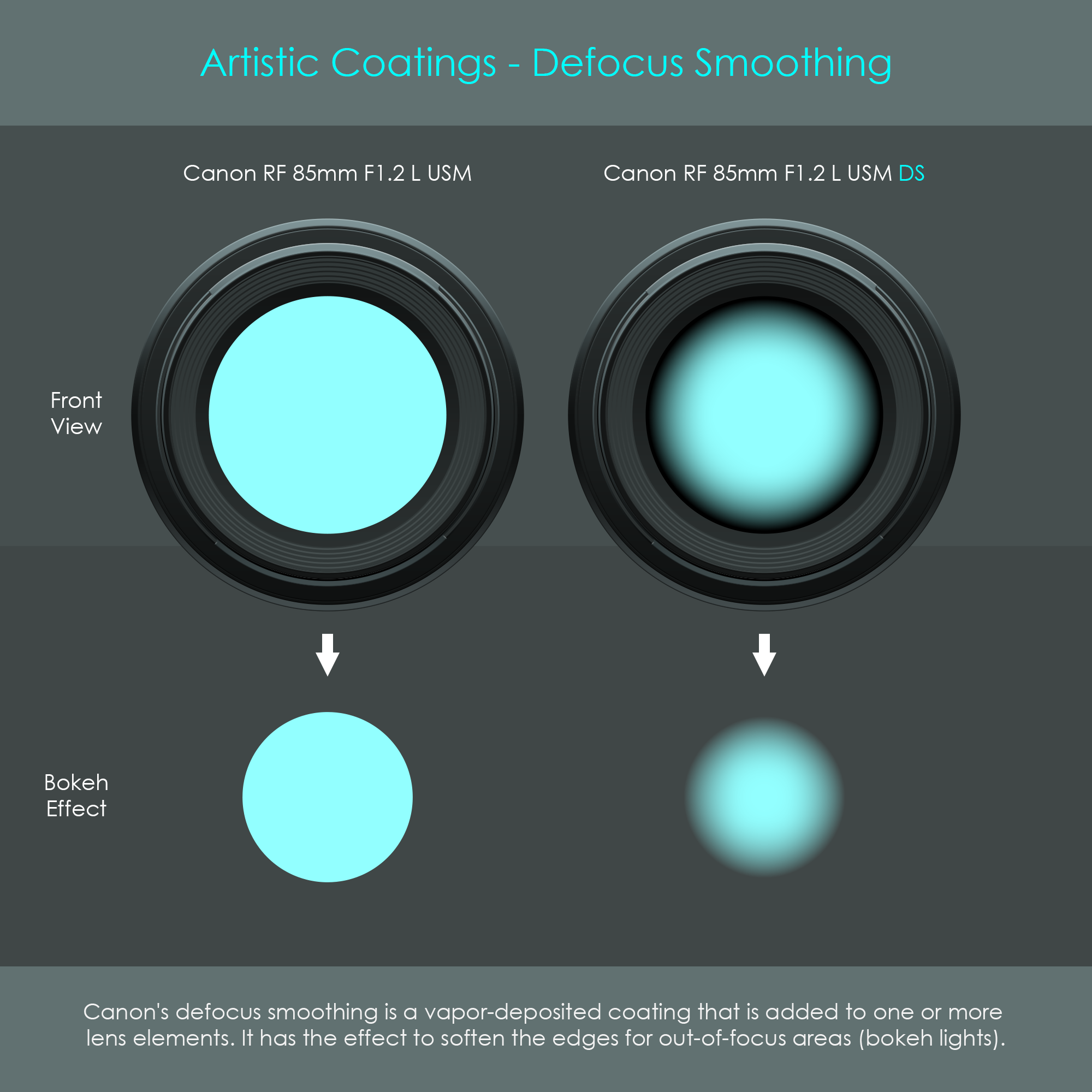
Canon's defocus smoothing (DS) coating is used to create uniquely soft renderings of out-of-focus image parts. Conventional optics usually form out-of-focus lights – also called bokeh circles – that are uniformly bright and have sharp outlines, whereas lenses with a DS coating render bokeh circles that are smoothly blurred.
Technically, this effect is realized by coating the surfaces of certain lens elements with a soft gradient that darkens towards the edges. The exact type of coating is also called edge-graduated neutral density filter coating. This coating does not significantly affect overall transmission of the lens but it gradually reduces the light transmission from the center of a coated lens element towards the edge. In the Canon RF 85mm F1.2 L USM DS, the DS coating is applied on two surfaces of lens elements, one closely in front and one closely behind the aperture stop respectively. This ensures that the gradient only shows on out-of-focus areas of the image and will affect all field angles in a similar way. The DS coating does not show as a vignetting effect in the edges of the photograph.
The front lens element of a photographic lens is usually most exposed to the elements. Rain, dirt, dust and sand can directly affect the quality of a photograph, but such contaminants can also permanently scratch the front lens when cleaned off with improper techniques. Canon has developed a specialized protective fluorine coating – not to be confused with fluorite – to increase resilience of their front lens surfaces. The advantage of fluorine-based coatings lies in a combination of excellent scratch resistance, extremely low friction resistance (anti-stick), as well as oil and water repellency. Dust can easily be removed with an air blower and droplets of oil or water can be wiped off without using lens cleaners or solvents. Another advantage of fluorine coatings is that no static electricity is collected when wiping the lens with a dry cloth, and therefore no additional dust is attracted. The fluorine coating is usually applied to the exposed surfaces of the first lens element as well as the rearmost lens element, and it is deposited on top of any existing anti-reflective coating. The additional protection layer does not significantly reduce the effectiveness of an anti-reflective coating.