The Scottish physicist James Clerk Maxwell is best known for his formulation of the classical theory of electromagnetic radiation. This was the first theory that described electricity, magnetism and light as different forms of the same phenomenon. His work in optics also led to the discovery of the fisheye lens. In 1858, Maxwell published a theoretical design for a 'perfect lens' and listed three requirements for it:
In practice, these three requirements can very rarely be satisfied by an optical system. Especially thin lens elements with spherical surfaces commonly fail to focus image points with pinpoint accuracy. This does not occur due to production imperfections but even well manufactured lens elements suffer from aberrations. This chapter explains what types of optical aberrations exist and what optical designers and photographers can do to minimize their effects.
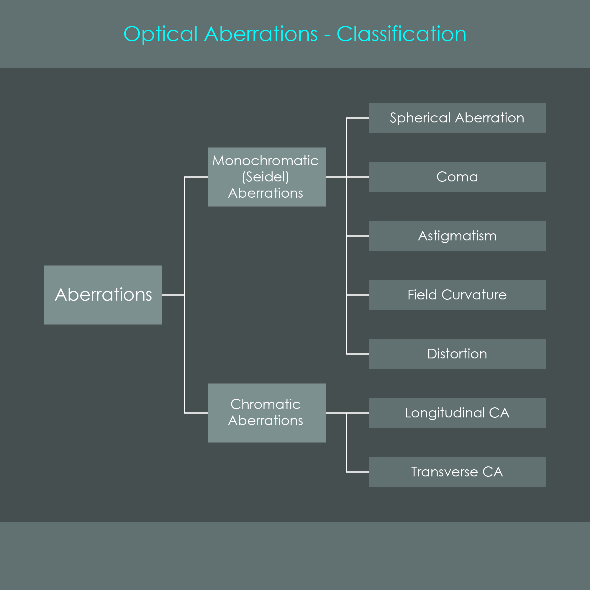
Optical aberrations are anomalies in imaging systems that cause image points to be blurred, distorted or discolored instead of properly focused. There are two main categories of optical aberrations:
The diagram summarizes these categories of imaging defects. An optical system usually exhibits a combination of aberrations as many of them are related with each other. In some lenses one type of aberration may show more than the other, and well-corrected camera lenses show very little defects overall. However, an optical system is never completely free of optical aberrations.
The primary cause for monochromatic aberrations is the use of spherical surfaces for lens elements and the fact that refraction varies in each concentric annular zone of such a surface. They are called monochromatic because their appearance is not influenced by the wavelength (color) of light that travels through the optical system.
This type of imaging defect is usually generated by spherical lenses. Spherical aberration occurs when rays of light from on-axis object points fail to meet at the same image point. The reason for this phenomenon is that rays of light with a greater height of incidence (further away from the optical axis) are refracted stronger than rays with a smaller height of incidence (close to the optical axis). As a consequence, as spherical lens typically has different focal points for different heights of incidence.
The outermost rays of incident light – called marginal rays – define the extreme limits of the aperture or field of view. These get refracted on the outermost zone of the spherical lens and they converge at a marginal focus point first. Quite the opposite applies to the incident rays of light that lie very close to the optical axis – called paraxial rays – these get refracted just very slightly where the lens surface is almost perpendicular to the axis, and they converge later at a paraxial focus point. All other rays come to a focus between marginal and paraxial focal points, and they form a ray pattern also referred to as caustic. This phenomenon is also considered to be a variation of the focusing ability of the lens with aperture.
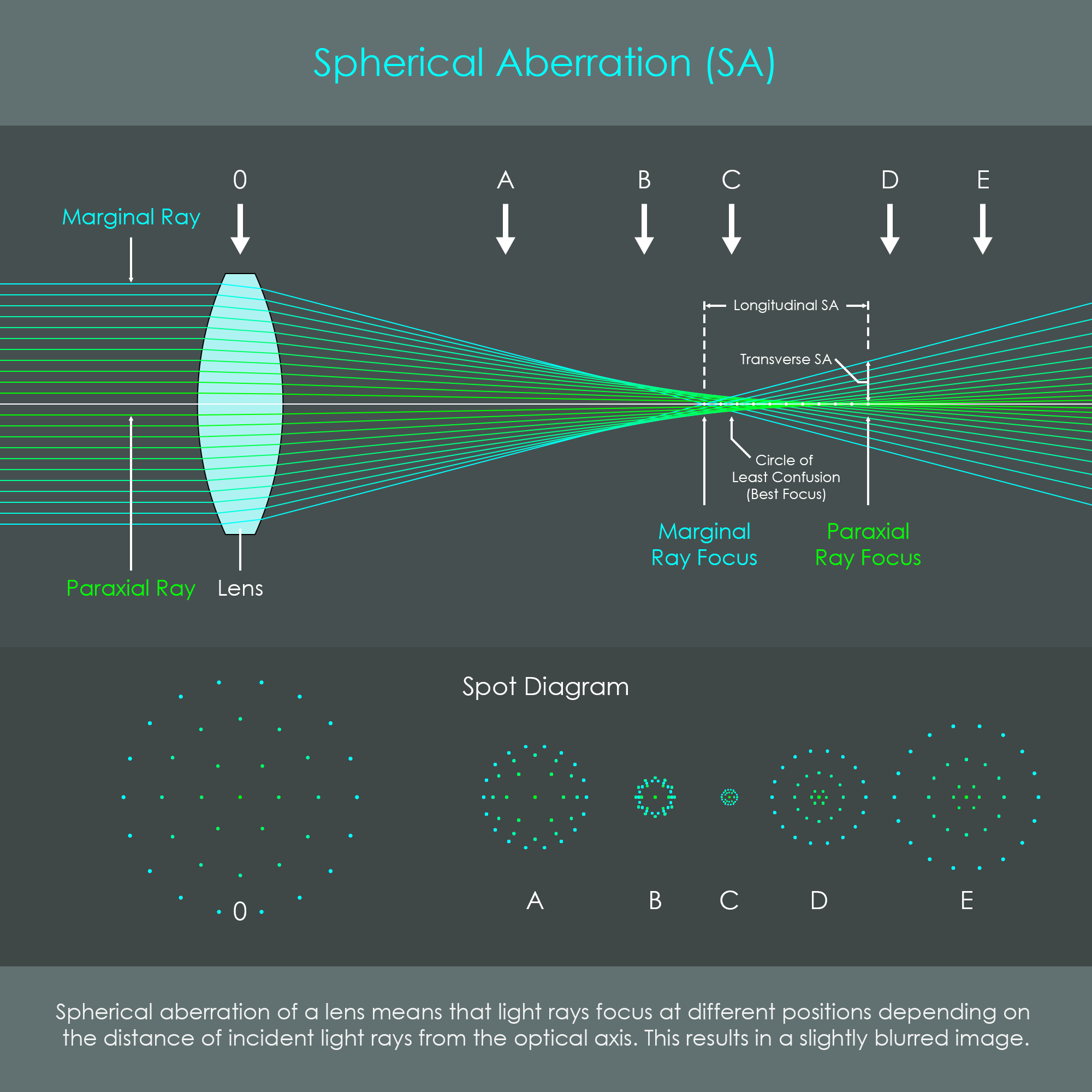
The illustration shows a case of positive spherical aberration of a converging lens. There is also negative aberration for diverging lenses where the marginal rays focus behind the paraxial focal point. Note that colors used in the diagram do not represent spectral hue (color of light) but the height of incidence for individual rays.
The cross-sectional area of the ray bundle varies with the position along the optical axis. There is only one position within the caustic that has a relatively small cross section. This smallest possible area is called the circle of least confusion and a photographic camera will typically detect best focus at this focal position. The image will not be perfectly in focus (neither at the center nor at the corners) but it is the best option with the presence of spherical aberration. The diagram illustrates the concept of spherical aberration in an optical system.
For single lens elements this imaging defect can be significantly reduced by using an aspheric surface. If an optical system uses multiple lens elements, spherical aberration can often be reduced or even canceled out by overcorrecting other lens elements. The use of symmetrical doublets is also common practice to reduce aberrations of various types. Finally, a photographer can also take steps to suppress spherical aberration. If a lens shows some defocus at the largest aperture, reducing the effective aperture of the lens can help to increase sharpness.
Coma is an optical aberration which causes rays of light from an off-axis object point to form a trailing comet-like blur instead of a focused point. This aberration is even named after the unique appearance of these little comets. The reason for this phenomenon is that principal planes can only be treated as straight planes in the axial region. In reality they have a curved geometry. It was shown for spherical aberration that spherical lenses have a slightly variable focal length depending on the zone through which rays of light are passing. Different focal lengths not only cause different focal points but also different transverse magnifications. This is why coma is also considered to be a variation of magnification with aperture. When an oblique bundle of light from an off-axis image point is imaged through a spherical lens element, coma will be observed.
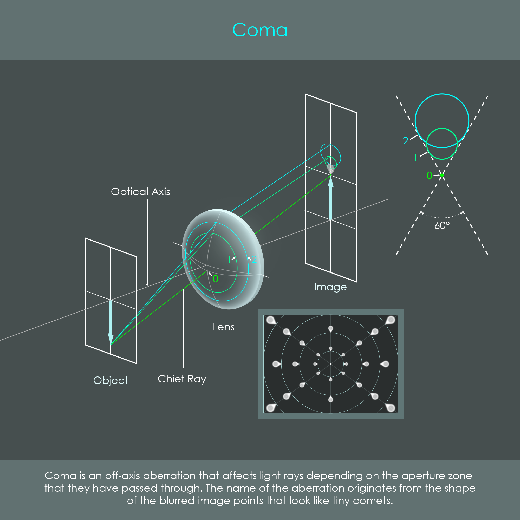
The illustration shows the projection of an off-axis object point (the tip of the arrow) through a spherical lens and the formation of a typical coma pattern on the image. Rays of light travel through various zones of the lens. The chief ray enters the lens very close to the optical axis, and therefore no significant aberration occurs for this ray. By contrast, other rays are travelling through outer zones 1 and 2, and these are affected by the increasing focal power and transverse magnification of these zones: Rays that pass through a zone get imaged as a ring that increases with the size of each zone. The total number of zones is what forms the typical comet pattern. Note that all light rays contributing to the comet shape originate from the same off-axis image point, but they have travelled through different zones of the lens.
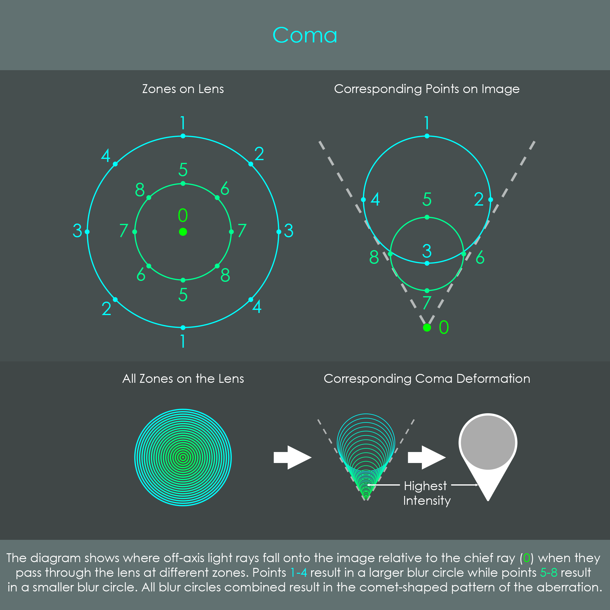
The diagram compares the zones of the lens and the corresponding image that occurs in the presence of coma. Each ray ends up in a very particular portion of the image, indicated by numbers 0 through 8. The lower section is an approximation of the light intensity inside the comet shapes.
Coma exists in two forms: Coma is positive when the outer zones of a lens cause larger transverse magnification. In this case the coma image has the pointed side facing the optical axis and the zonal circles oriented towards the edges of the image. The illustration on the projection of coma shows the positive type of coma. By contrast, coma is negative when the outer zones of a lens cause smaller transverse magnification so that the rays that pass through outer zones reach the image plane closer to the optical axis. In this case the coma image is inverted, with zonal circles facing the optical axis and the pointed side oriented towards the edges of the image.
Coma is related to spherical aberration, but it is classified as a separate effect. While spherical aberration is an imaging defect that shows for on-axis points, the presence of coma can only be observed for off-axis points. The intensity of coma varies with the angle in which incident light hits the lens. In the presence of coma, a lens is able to form a sharp image in the center but starts to show more intense comatic patterns towards the corner region of the image. This type of aberration is especially noticeable in astro-photography where stars should be tiny spots but are instead imaged as tiny comets.
Astigmatism is an imaging error where light rays that travel in two perpendicular planes have different focal points. Therefore, an astigmatic lens doesn't form a single image point but rather produces two line images which are arranged one behind the other and are aligned perpendicular to one another. The term originates from the Greek combining the prefix 'a-' which means without and 'stigma' which means spot or point.
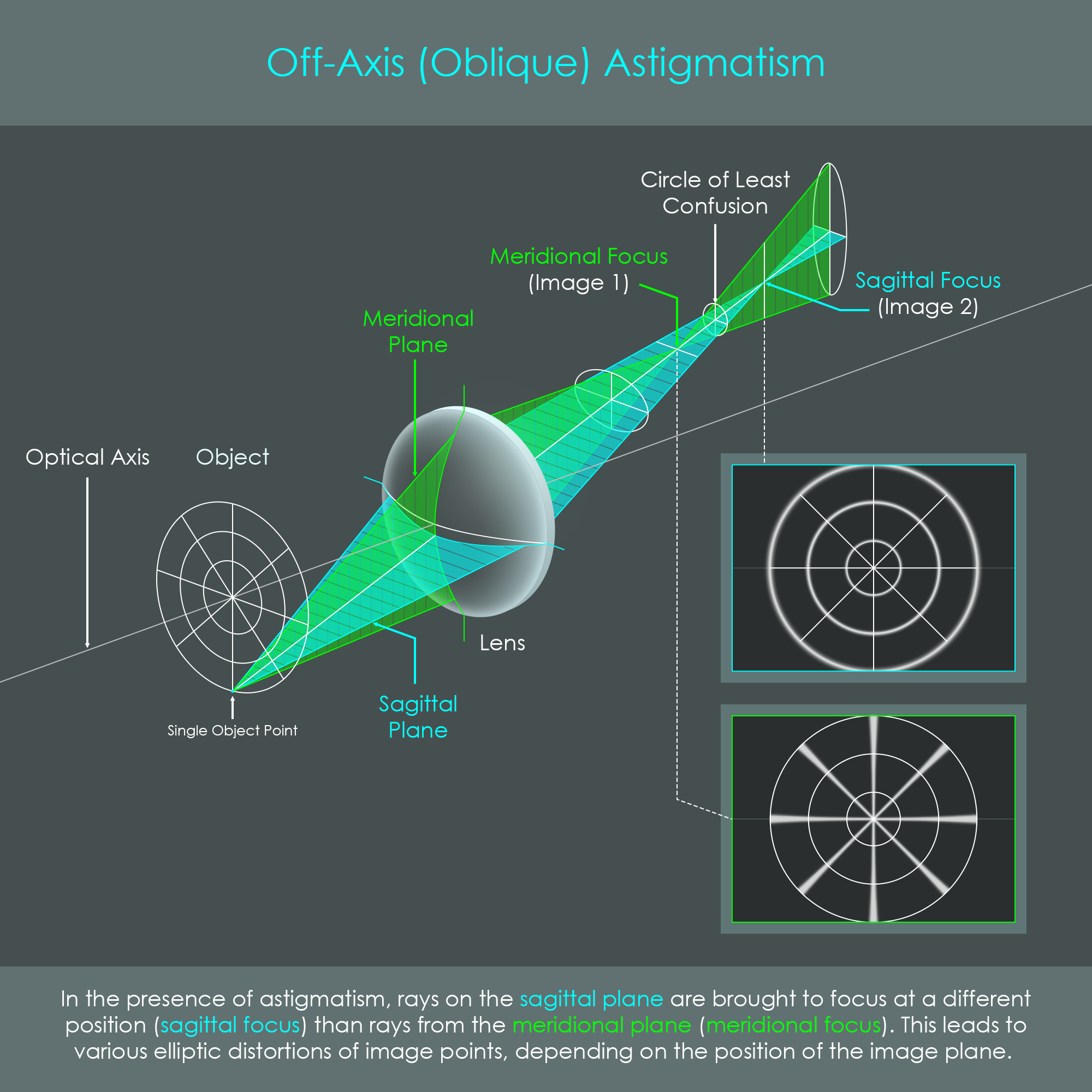
Astigmatism can be explained by looking at two planes of light rays:
In the presence of astigmatism, the meridional and sagittal rays converge at different focal points along their optical paths. These focus points are called the meridional and sagittal focus respectively. The reason why rays meet at different points is because the lens has different refractive power for one plane than the other. For rays in the meridional plane, the curvature of the lens appears to be stronger than for sagittal rays.
An astigmatic lens produces two focal lines or line images instead of one properly focused point. The image at the meridional focus is a line oriented in the direction of the sagittal plane. In this position the sagittal plane hasn't fully converged yet. The image at the sagittal focus is a line oriented in the direction of the meridional plane. In this position the meridional plane is diverging again. The spoked wheel in the illustration clarifies how astigmatism looks when the image recorded either in the meridional focus position or the sagittal focus position.
The two planes are just simplifications of the complete bundle of rays. The entire configuration of light rays refracted through an astigmatic lens is called the 'Conoid of Sturm'. The illustration shows a model of such a Conoid of Sturm formed by an astigmatic lens.
After leaving the exit pupil of an astigmatic optical system, the cone of light takes on an oval shape. Further behind the oval becomes flatter until it comes to a line (1st focal line, meridional focus). After that light rays expand again until they form a perfect circle, called the circle of least confusion, and from there light rays are flattened again but this time in the other direction until the second line is formed (2nd focal line, sagittal focus). Further behind the bundle takes on another oval shape that is now perpendicular to the first oval that was formed.
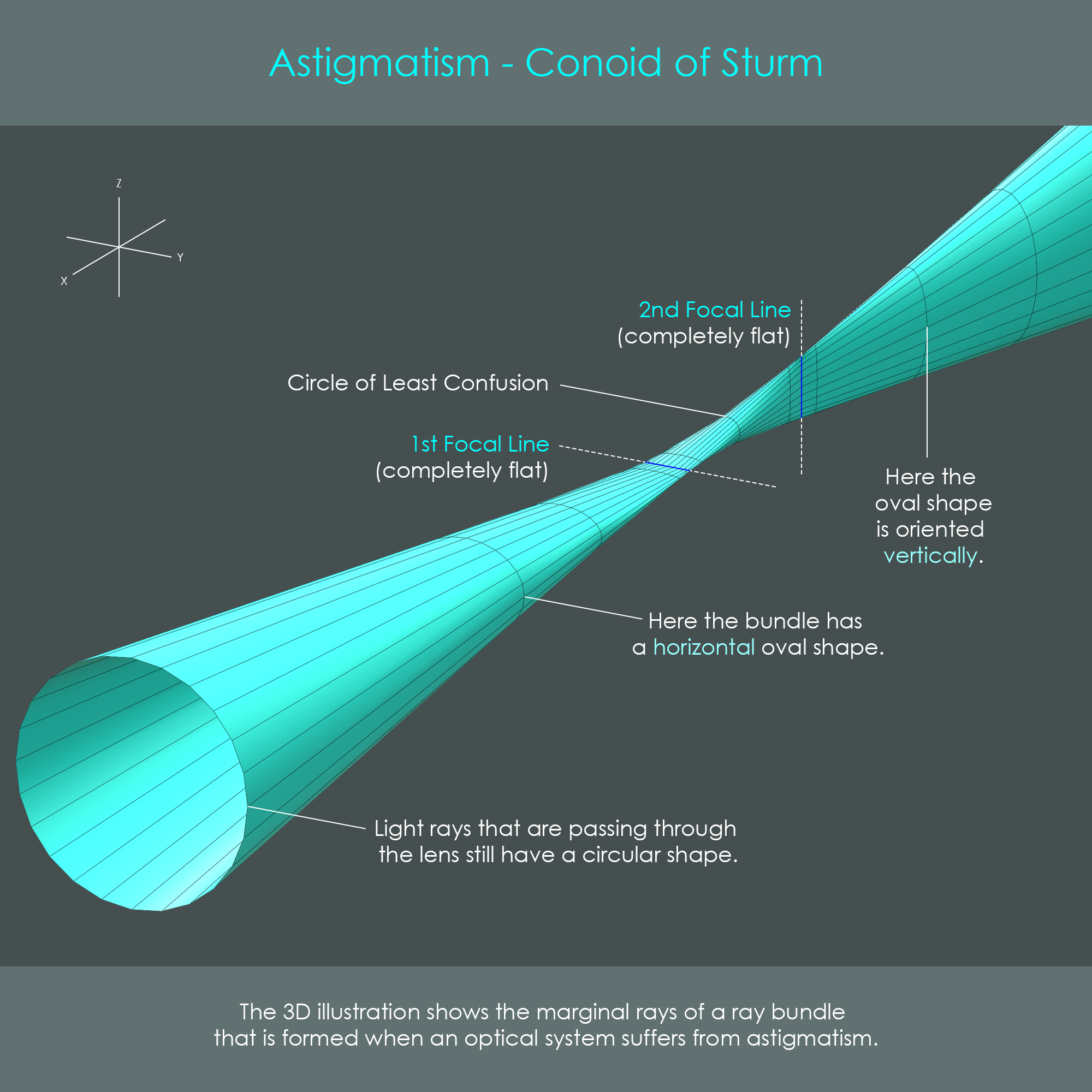
The circle of least confusion is an area of the cone that is free of distortion. Although it is not a sharply focused point, it is considered the best compromise for an image position in an astigmatic optical system. Rather counterintuitively, the circle of least confusion is not precisely halfway between both line images. It is typically a bit closer to the meridional focus, approximately at a 40% position between two line images.
Astigmatic errors can often be minimized or corrected during the design of optical systems. Therefore, shapes, optical materials and proper spacing of individual lens elements as well as aperture sizing can play decisive roles in the reduction of astigmatism.
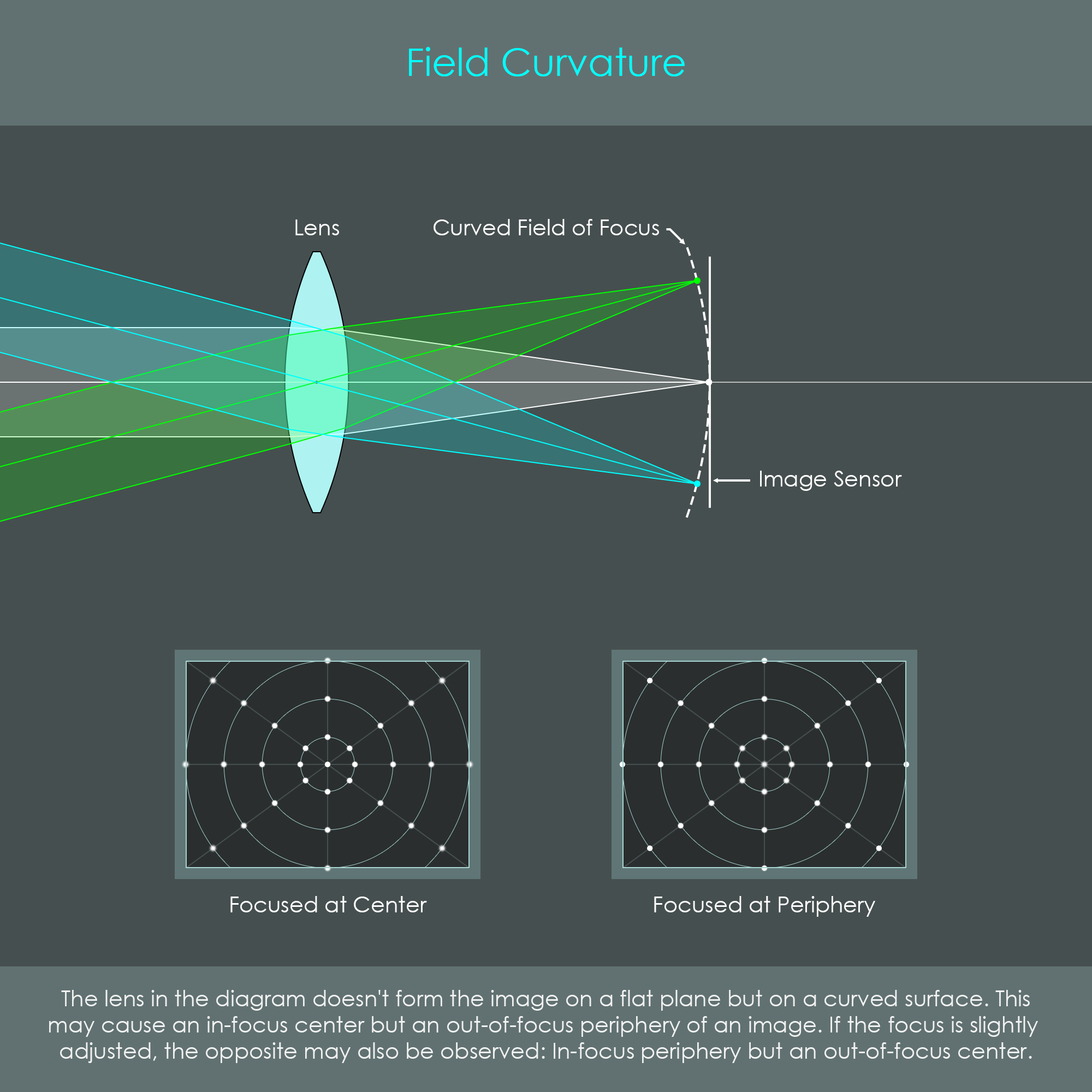
This optical aberration, also called Petzval field curvature, describes the fact that an object perpendicular to the optical axis cannot be brought into a uniformly focused flat plane on the image side. The reason therefore is again the curved design of optical lenses that tend to introduce deviations for off-axis rays. As photographic cameras always have flat image sensors this automatically results in the problem that objects do not appear focused all across the image. If the focus is adjusted for the center, the presence of field curvature will cause the periphery to show some defocus. Vice versa, if the focus is adjusted for the periphery, field curvature will cause the center of the image to go out of focus.
Distortion or curvilinear distortion is an optical aberration describing how the transverse magnification that a lens produces is not constant. It only affects rays of light from off-axis points. If an image gets distorted by a lens, its transverse magnification changes across the field of view.
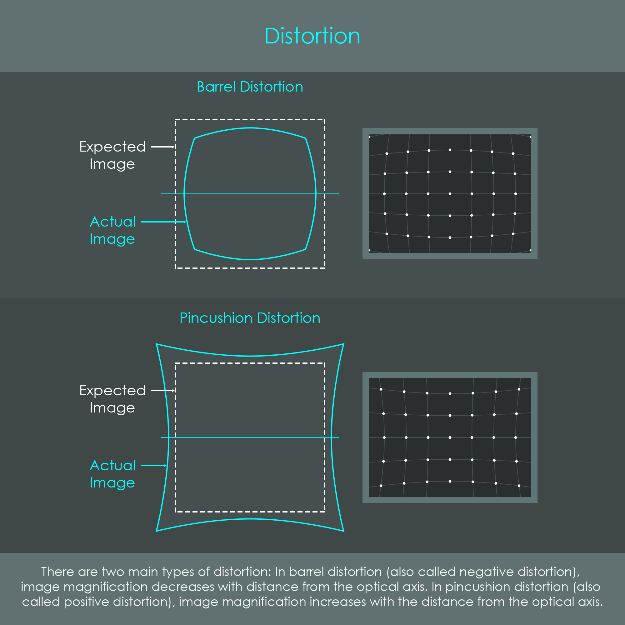
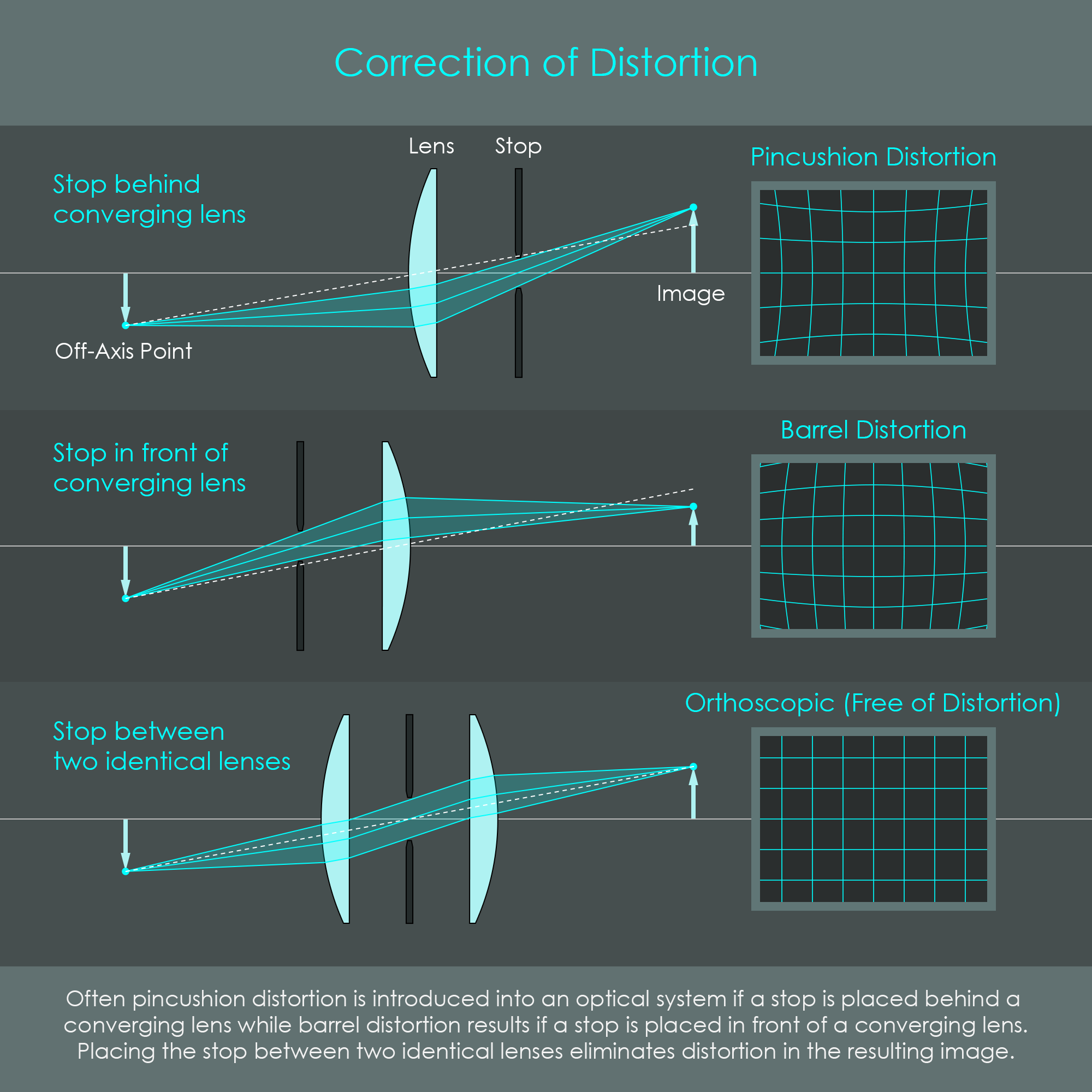
The illustration shows two of the most common types of image distortions: Barrel and pincushion distortion. The dashed line represents the expected image outline.
Transverse magnification is the ratio Y'⁄Y where Y' is the produced image height and Y is the original object height. An optical system that is free of distortion is called orthoscopic. The image in such a distortion-free optical system may have a different size than the object but identical proportions. This means that for all chief ray angles the ratio tan θ'⁄tan θ must be constant.
Distortion occurs when this ratio is not a constant for all angles which means that the ratio is almost constant for small angles θ but when θ becomes larger the angle θ' starts to increase at a slower (barrel distortion) or faster (pincushion distortion) rate.
Distortion is determined by the optical design of a lens and it is primarily caused by the presence of an aperture stop. An aperture stop in front of a converging lens (at the object side) results in barrel distortion while an aperture stop behind a converging lens (on the image side) results in pincushion distortion. Lenses with larger fields of view (smaller focal lengths) typically show greater amounts of distortion.
It should be noted that unlike other optical aberrations distortion does not degrade image quality. When other aberrations fail to produce sharply focused image points, the resulting blur reduces information from the final image. By contrast, distortion is an aberration that only displaces image information geometrically. This means that distortion is one of the few imaging defects that can be reversed by digital post-processing. In the presence of very strong distortion, however, digital correction will affect the resolution in the adjusted areas.
Chromatic aberrations describe imaging defects that affect the accurate color reproduction of an image. The name originates from the Greek word 'chroma' and means color. The primary cause for chromatic aberrations is dispersion where light from short wavelengths (violet / blue light) is refracted stronger than light from long wavelengths (red light). You can read more about dispersion in the chapter about optical materials.
Most optical glasses have a variable refractive index depending on the wavelength of light that is passed through. If white light is passed into a glass prism it gets dispersed into the complete spectrum of visible light. Looking at a converging lens element it can be seen that it is wider in the center and it gets narrower towards the edges. That is almost the shape of a prism, and therefore white light that is passed through a lens is dispersed in a very similar way.
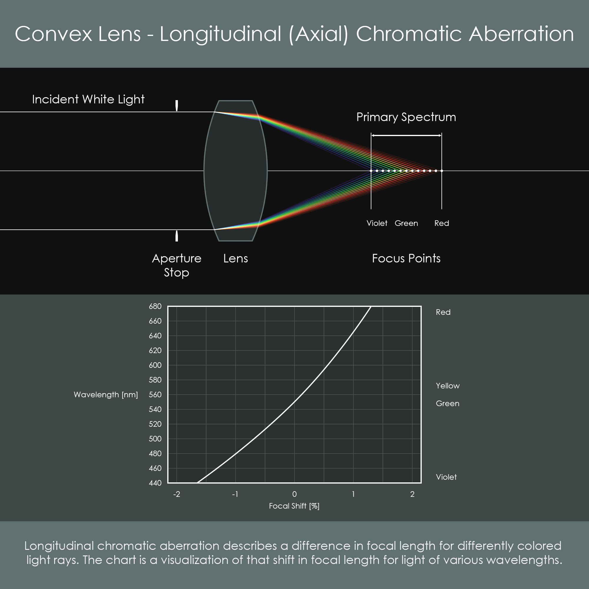
Longitudinal CA describes that a lens element has different focal lengths depending on the wavelengths of light. A lens has a slightly shorter focal length for violet / blue light and a slightly longer focal length for red light. Green light focuses in between. This is what causes a primary spectrum to appear along the optical axis, preventing a white object point to form a perfectly white image point. Instead, an image that suffers from longitudinal CA shows color fringes around contrast edges, both for on-axis and off-axis points.
CA is usually more visible at wider apertures, because light is refracted more at the outer zones of a lens element, and a stronger refraction usually leads to some stronger dispersion.
Transverse CA is also caused by dispersion, but it affects the transverse magnification of different light colors. It is therefore also called CA of magnification. This type of CA affects off-axis rays and it causes a difference in the size of red, green and violet color images. An incident chief ray of white light is dispersed into a set of chief rays, one for each color respectively. The green chief ray is used as a reference line. The violet chief ray is bent more towards the optical axis than the green ray, and it also causes the violet image to be slightly smaller than the green one. The red chief ray is bent less towards the optical axis than the green ray, and it causes the red image to be slightly larger than the green image. This again causes a primary spectrum but here it is oriented transversely. The deviation of image sizes increases with the angle of incidence. Photographers most commonly encounter uncorrected transverse chromatic aberration as red and blue color fringes in the corners of their images.
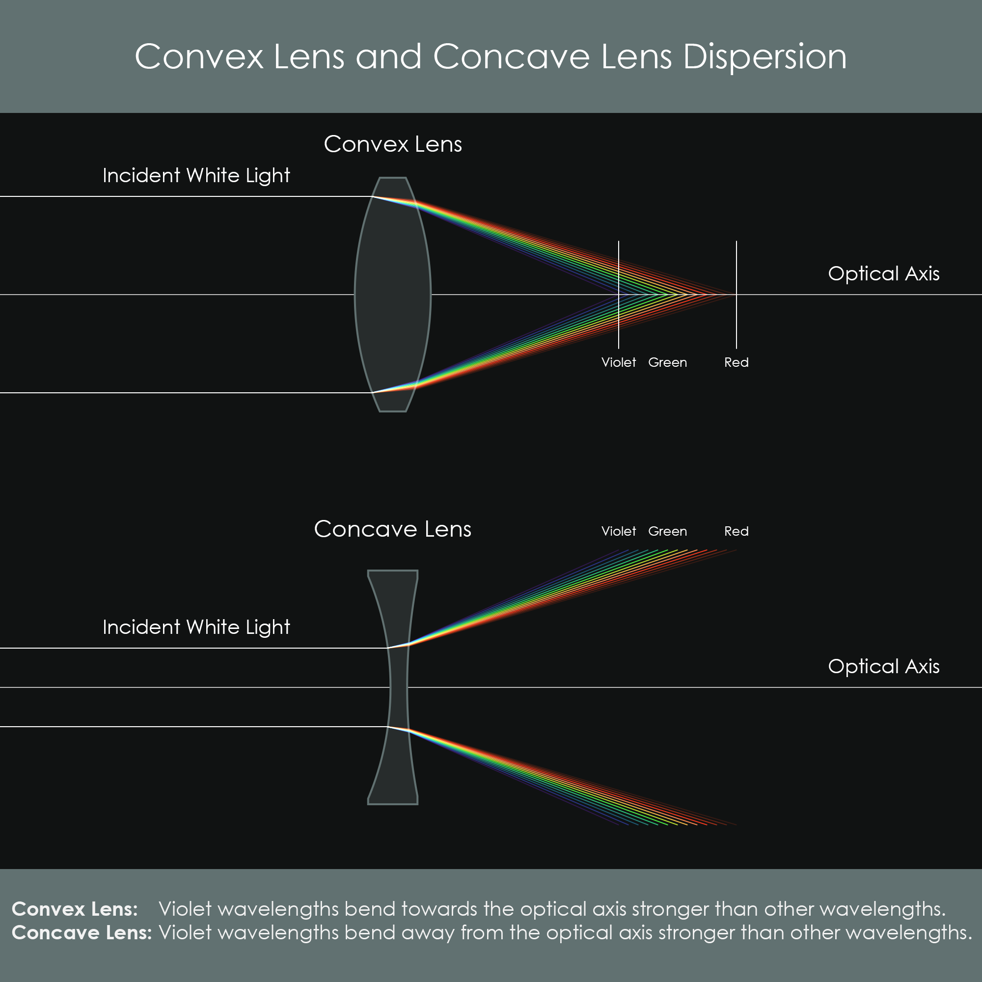
When white light is passed into two lenses of convex and concave shapes respectively, the different colors of light are refracted with similar strength (violet / blue light is always refracted strongest) but the convex lens refracts light towards the optical axis while the concave lens refracts it away from the optical axis. By placing both types of lenses behind each other, the second refraction sort of counteracts the first refraction. Using the right materials and lens shapes this can also reduce chromatic aberration, as will be detailed later.
Monochromatic aberrations are primarily caused by the curvature of a lens surface. To reduce these types of aberrations, optics designers typically adjust and refine lens geometries, lens spacing, and the aperture stop position to improve an optical system.

There are various approaches and techniques to reduce spherical aberration (SA):
For a single lens, coma can be partially corrected by bending the lens. Using a plano-convex lens with the convex side facing the object can help to minimize coma. Additional correction can be achieved by designing the lens elements symmetrically around the aperture stop. In addition, reducing the effective aperture of the lens can greatly reduce coma. Once a camera lens is corrected for spherical aberration and coma, it is called an aplanat or aplanatic lens.
Again, lens bending and having a symmetrical lens design with an aperture stop at the center can help minimize astigmatism. Additional correction can be achieved by designing the optical system with additional lens elements that have a similar but opposite astigmatism so that the overall aberration is cancelled out. Also reducing the effective aperture of the lens can reduce astigmatism. Once a camera lens is corrected for spherical aberration, coma and astigmatism, it is called an anastigmat or anastigmatic lens.
Decreasing the field of view is one option to minimize the curvature of field. While effective, this is usually not considered a real correction technique as most lenses have a specified field angle that is required for their application. Some level of true correction can be achieved by adding a negative field-flattener lens element to the optical system. This lens element produces an opposite field curvature, and therefore cancels out the original curvature. A field-flattener is positioned close to the focal plane so that it doesn't strongly affect other aberrations. Again, reducing the effective aperture of the lens will also reduce field curvature.
Chromatic aberration occurs due to dispersion caused by optical materials. Reduction or correction of chromatic aberration is typically done by combining various lens elements with different shapes and optical materials. Even though chromatic aberration is very challenging to correct and often impossible to eliminate entirely, many approaches lead to high levels of correction.
It was shown that an optical system without any color correction – also referred to as a chromatic lens – will form a primary spectrum chromatic aberration (both in longitudinal and transverse orientation). In theory, it would be perfect if an optical system would bring together every wavelength of light at the same focal point. In reality, however, this is impossible to achieve even with modern materials. Common approaches are successful in bringing only few wavelengths together at one focal position while the other wavelengths remain at incorrect focal lengths. Over the past 200 years, optical designers have come up with various ways to minimize color defects. The design process to correct chromatic aberration is called achromatization. If an optical system is well corrected it typically shows very little longitudinal and transverse color defects.
A very common approach to minimize chromatic aberration is to combine lens elements with different dispersive properties and opposite refractive powers. Under certain conditions this will bring the focal points of the individual wavelengths closer together. Some wavelengths can even be brought to the same focal length. Corrective lenses are typically grouped or cemented together to doublets, triplets or arrays of more than three lenses. An achromatic doublet and an apochromatic triplet will be explained below.
Achromatic describes the level of achromatization where two wavelengths are brought to a common focus. It is typically the most extreme wavelengths of red and violet light that are getting adjusted to have similar focal lengths. Doublet describes that a pair of lens elements is used, typically one convex and one concave lens element.
It was described in the chapter about Optical Materials that glasses can be broadly categorized according to their refractive index and their amount of dispersion. In an achromatic doublet lens, the front lens element is usually a convex crown glass (low index, low dispersion) and the rear lens element is usually a concave flint glass (high index, high dispersion). The radii of the inner surfaces are often precisely identical so that both lens elements can easily be placed or cemented together.
Mathematically, a lens doublet is achromatic if the individual focal lengths of lens elements used are the reciprocal of their Abbe numbers:
- f1⁄f2 = V2⁄V1
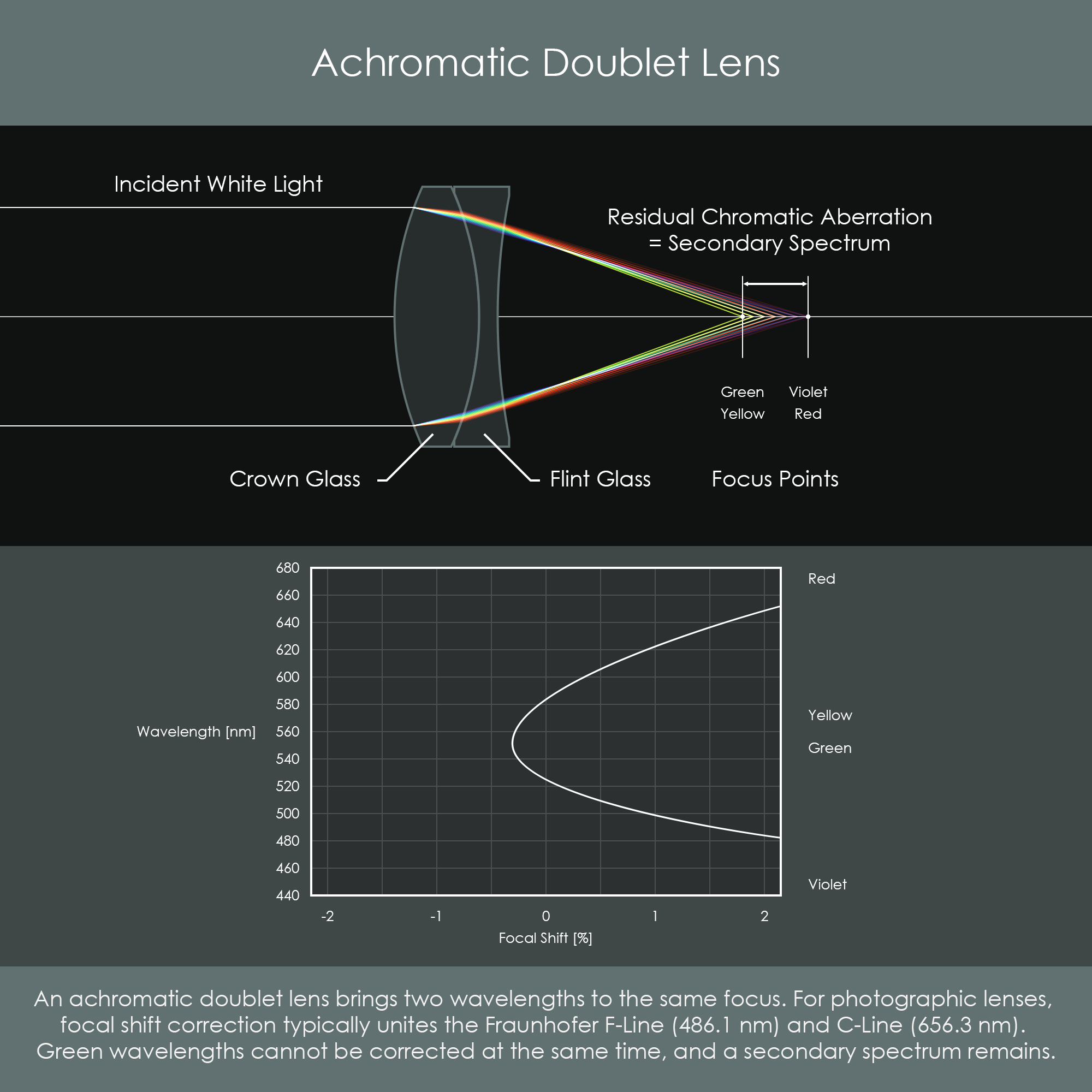
While an achromatic doublet is successful in correcting red and violet light in terms of focal length, it is unable to bring other wavelengths to the same focal length. For that reason, a secondary spectrum is formed where red / violet is focused further away from the lens and green / yellow is focused closer to the lens. A secondary spectrum is produced on both longitudinal and transverse chromatic aberration. However, the secondary spectrum is spread over a shorter length longitudinally and transversely which means that color reproduction and contrast have improved compared to a chromatic lens.
The definition of a secondary spectrum or secondary color is the length in which an achromatic lens still shows wavelength-dependent variations in focal length. Secondary spectrum ranges from yellow / green wavelengths of light to blue / violet wavelengths. Photographers most commonly encounter secondary spectrum as yellow and magenta color fringes in the corners of their images.
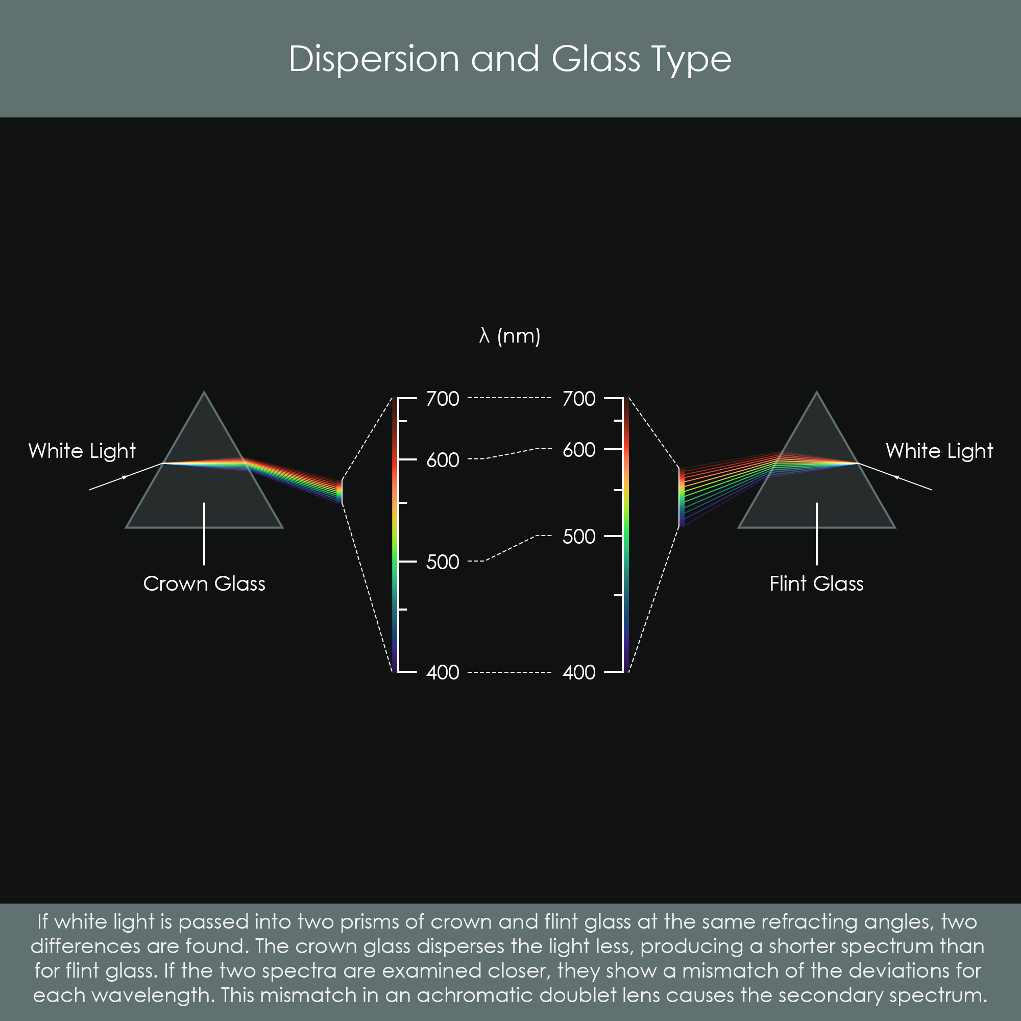
The reason for secondary spectrum to appear can be found in the optical properties of crown and flint glasses. If the spectra produced by passing white light into two prisms of crown and flint glass respectively are examined, two differences can be found: Crown glass disperses light less, producing a shorter spectrum than for flint glass, but expanding the former to match that from the flint also shows a mismatch of the deviations for each wavelength. This mismatch in an achromatic lens causes the secondary spectrum (Sidney F. Ray, Applied Photographic Optics, 2002, p. 112).
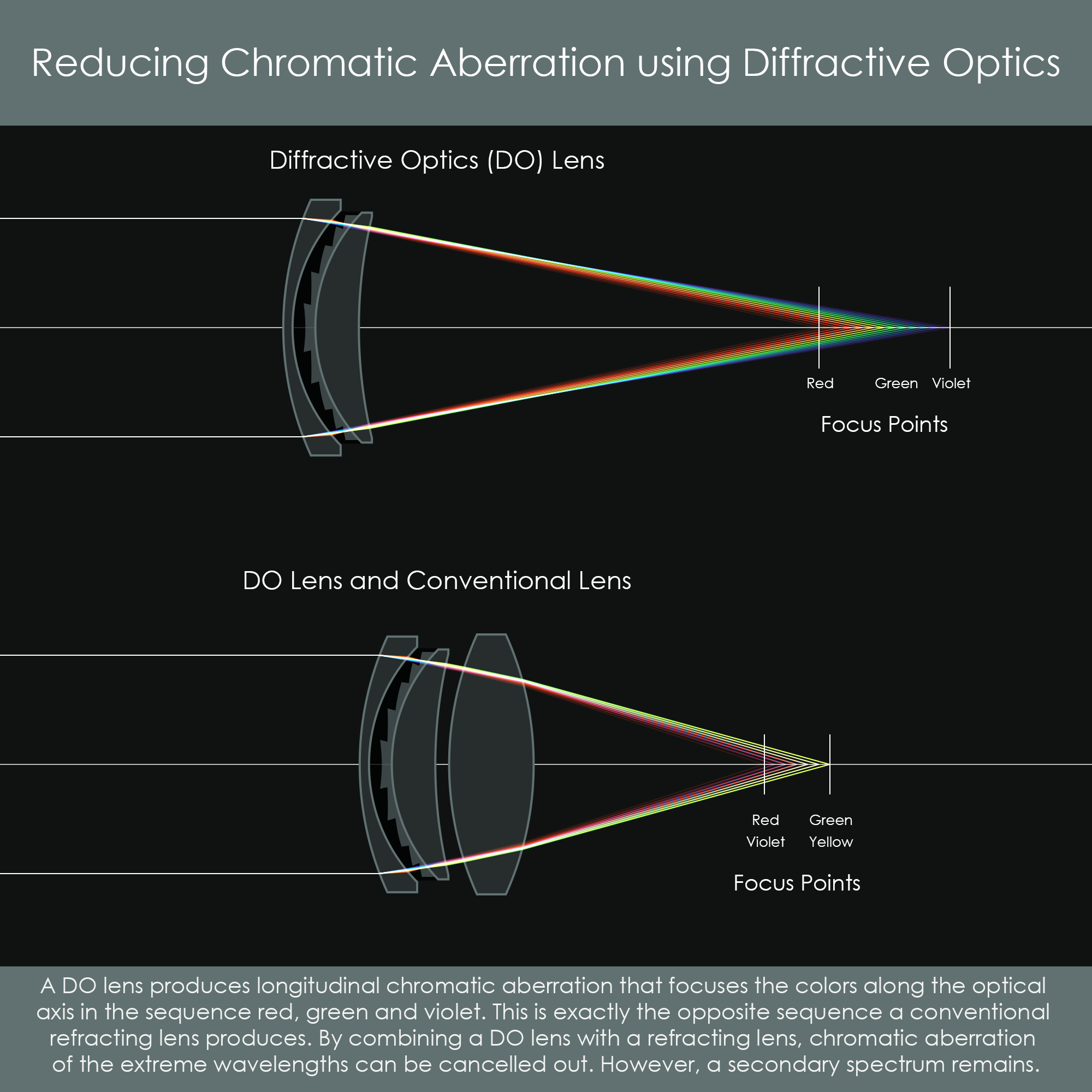
For a description of a lens using diffractive optics (DO) please see the chapter about Lens Elements. Chromatic aberration also occurs with multi-layered DO lenses. The diffraction grating disperses light in opposite order compared to conventional optical glass: Red light is refracted the most – coming to a focal point first, and violet light is refracted the least – coming to a focal point last. This can be utilized to counteract the chromatic aberration induced by a conventional lens. Combining a DO lens with a refractive lens reduces chromatic aberration very effectively. There is still a secondary spectrum but using a DO lens also brings the advantage of weight reduction.
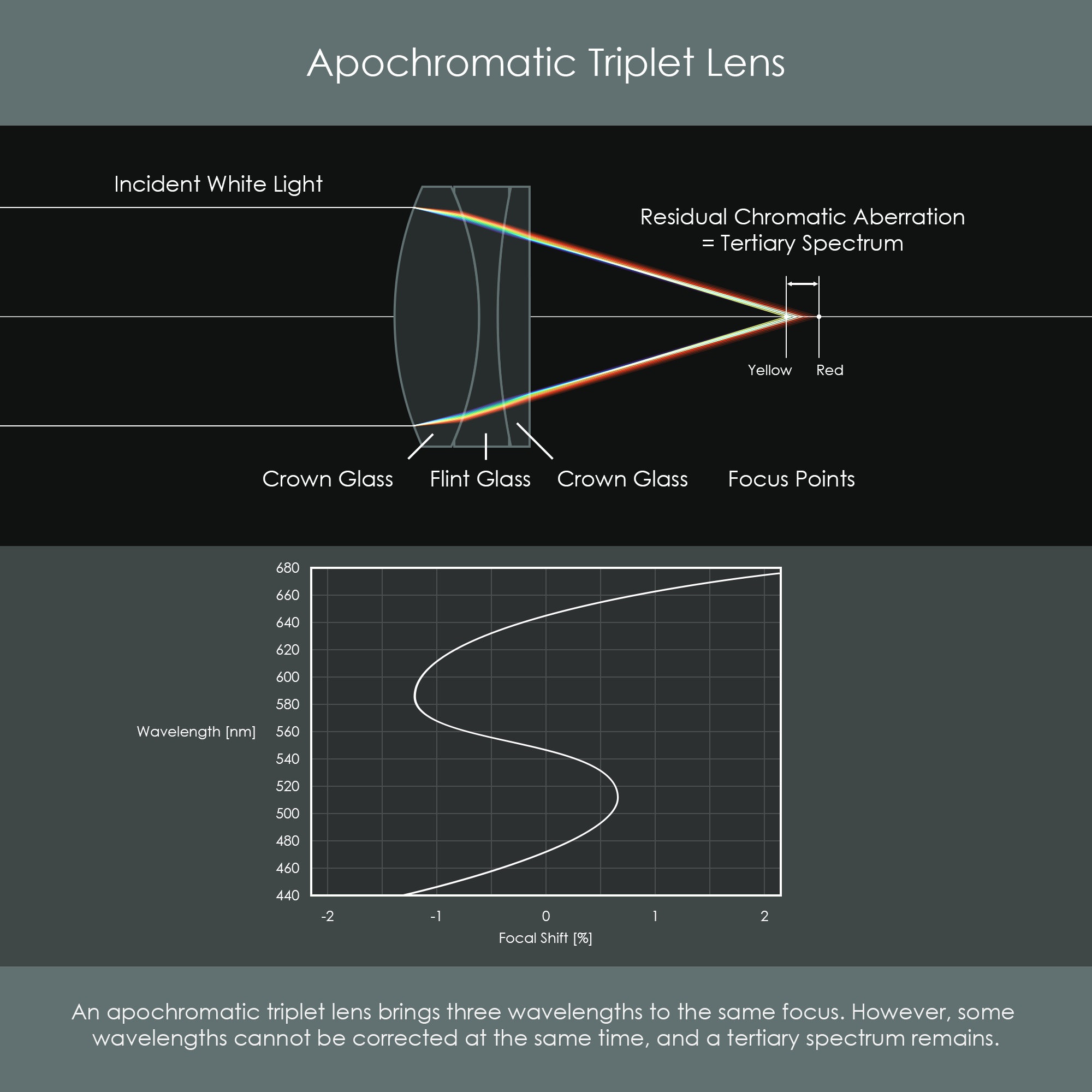
Apochromatic describes the level of achromatization where three wavelengths are brought to a common focus. It is typically the red, green and blue wavelengths of light that are getting adjusted to have similar focal lengths. Triplet describes that three lens elements are used.
The remaining wavelengths of light that cannot be brought to a common focal length form a tertiary spectrum. An apochromatic triplet lens achieves even better correction of chromatic aberration than the achromatic doublet because the axial length within the wavelength-dependent defocus occurs is reduced even further. An apochromatic triplet typically uses combinations of crown and flint glasses and variations of convex and concave lenses.
When compound lenses are designed it is crucial that convex surfaces of a lens element aren't touching other lenses surfaces as this would form pressure points and would cause imaging defects. In this context, optical designers speak of 'lens separation' which means the closest distance between two lens surfaces.
Both achromatic doublet and apochromatic triplet lenses can be designed by positioning crown and flint lenses close to each other but separated by an air gap. If this option is chosen, lens separation must not be zero. A more common technique to form lens groups is by cementing them together with very thin, optically transparent adhesive. Cementing is the only case where lens separation must be zero, and the surfaces that are cemented together must have perfectly identical radii of curvatures.
One type of cement very commonly used in optics is Canada balsam. It is a very pure material that has a refractive index of n=1.54 which is very similar to crown glass (n=1.55). In addition, it offers very low shrinkage when curing so it doesn't add stress to the glass elements.
In order to increase optical transmission of the color-corrective lens units, it is best practice to apply thin layers of anti-reflective coatings to their external surfaces after cementing them together. Read more about these coatings here.
Color correction of achromatic and apochromatic lenses can further be improved by adding some high performance materials into the equation. If the crown glass of an achromatic doublet is made of fluorite glass, secondary spectrum chromatic aberration gets reduced even further. The same applies to the use of UD and Super-UD glasses which can be used as crown glass.
In some optical systems, due to their individual configuration of lens elements and choice of optical materials, the greatest challenge is to correct blue and violet wavelengths of light. These colors are affected very differently by crown and flint glasses. As they are often refracted extremely strong, they sometimes tend to get overcorrected.
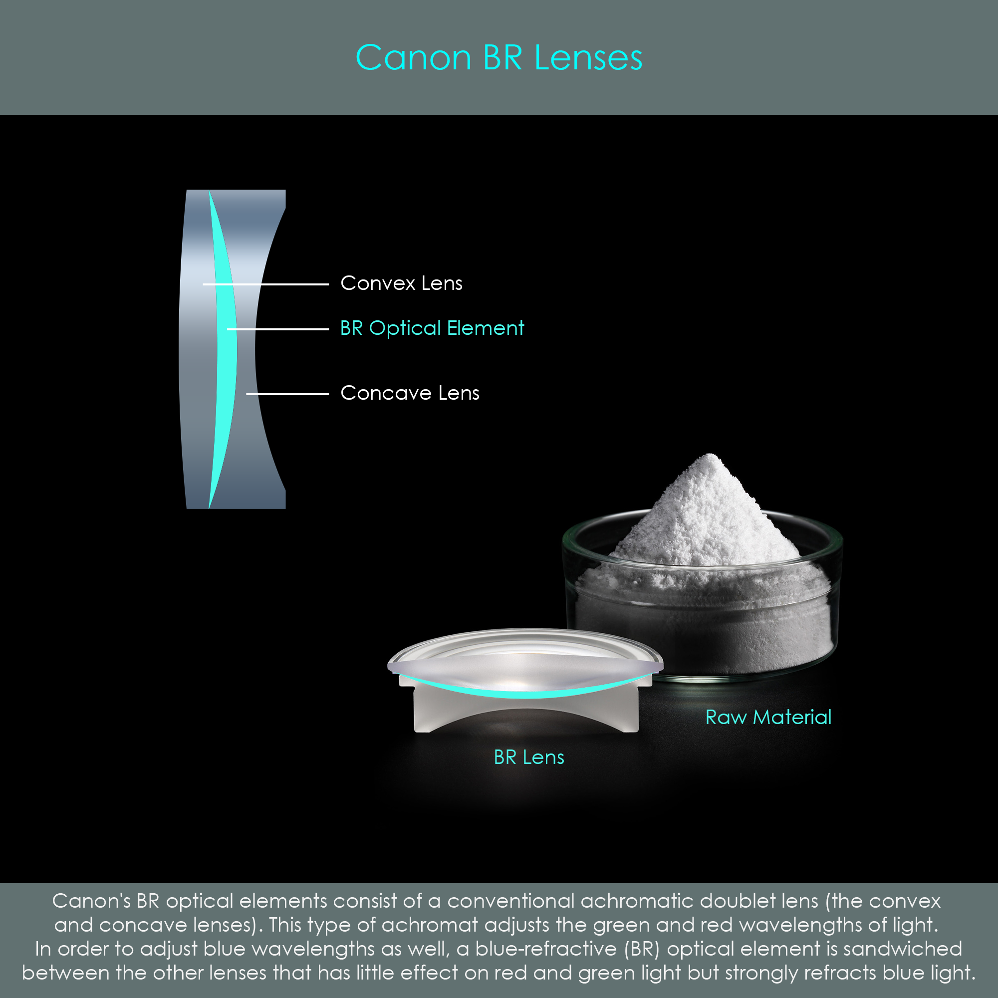
In 2015, Canon has found a solution to this problem – the BR lens. BR stands for blue spectrum refractive and it describes a newly developed organic (plastic polymer) material. A blue refractive lens element has different dispersive properties than traditional optical materials. More precisely, the refractive index of BR material is relatively consistent for most wavelengths of light but strongly increases for blue and violet wavelengths. This material can therefore be used to adjust blue and violet light in a relatively targeted way. The BR lens is sandwiched between conventional concave and convex lens elements, making it a triplet lens. The first Canon lens with a BR element embedded was the EF 35mm F1.4 L II USM, introduced in 2015. Color correction with BR elements achieves very impressive levels of color correction and overall image quality.