Modern photographic lenses usually consist of a multitude of individual lens elements. This chapter goes into the details about different types of lens elements and some common processing steps during production.
Each surface of a lens element can be categorized into two general types depending on the direction in which the surface is curved: While convex describes a lens surface that curves outwards at its center, concave describes a lens surface that curves inwards.
For optical designers and lens manufacturers, the directions in which both lens surfaces are curved is an important characteristic, but there are more properties that describe the overall geometry of a lens element. Some other properties are the diameter and the thickness of the lens element, and thus the dimensions and especially the weight. Another very important property is the uniformity (or non-uniformity) of individual lens surfaces which can be described in spherical and aspheric lenses.
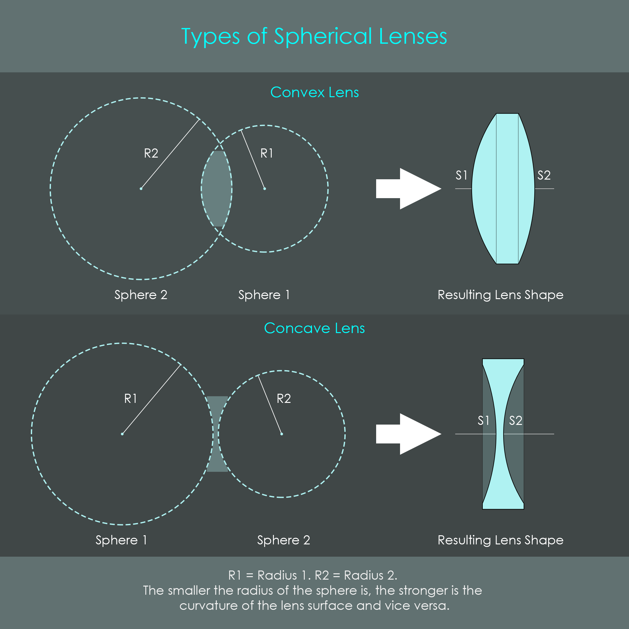
Spherical lenses are optical elements where each surface has a radius of curvature that is consistent across the respective surface. Each radius defines a sphere (hence the name spherical lens) that has exactly the same surface curvature of the manufactured lens surface. These are the most common types of lens elements found in photographic lenses.
The shape of a convex lens requires both of these imaginary spheres to overlap, and the lens is shaped like the intersection of both spheres. In contrast, the shape of a concave lens requires both imaginary spheres to be separated by a gap.
In optics, the surfaces of lens elements are usually numbered from left to right (S1, S2). The number of surfaces S can be up to 40 in some lens designs, and is always twice the number of optical elements inside an optical system. The radii are labelled with numbers that are identical with the surface numbers.
Note how the edges of the convex lens are flat. This is a very typical shape as it would lead to extremely sharp edges if both surfaces would be brought together at their original curvatures. Cutting the sharp edge from a lens element makes them easier to seat inside a lens barrel, and reduces some weight.
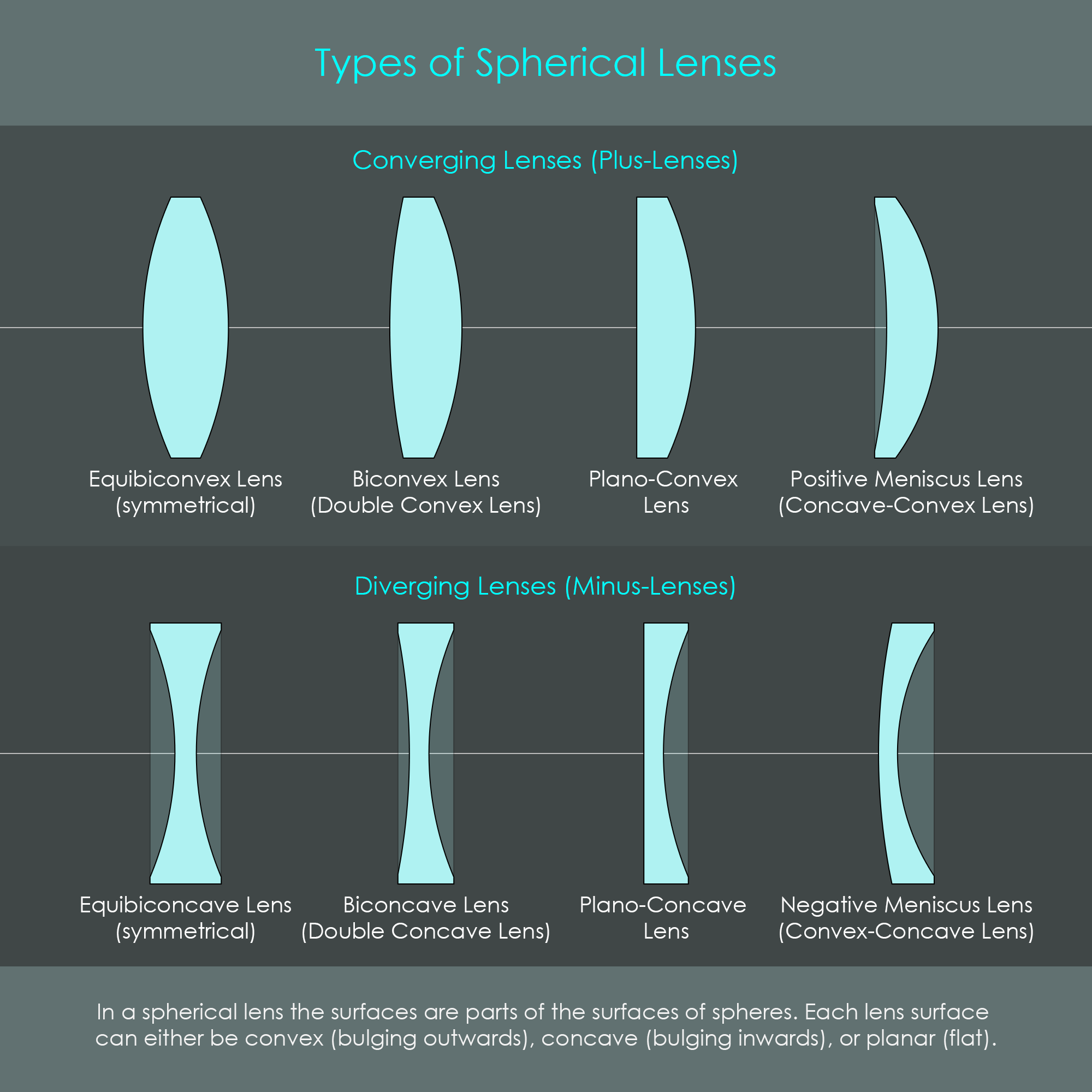
There are various types of spherical lenses. These differ in the combination of convex and concave surfaces, and their radii of curvature. Lenses that bring incoming (parallel) light to a focus are referred to as converging lenses, positive lenses or plus lenses. Conversely, lenses that spread incoming (parallel) light apart are called diverging lenses, negative lenses or minus lenses. The illustration summarizes all types of spherical lens elements, sorted by converging and diverging lenses.
Looking at individual surfaces of a lens, a single convex surface has positive refractive power whereas a concave surface has negative refractive power. A very common approximation in optical engineering is that a lens is positive (converges light) whenever the sum of the two refractive surface powers is positive. Similarly, a lens is negative (diverges light) whenever the sum of the two refractive powers is negative. However, there are technically some specific instances where the sum of the refractive powers of the surfaces is positive, but the lens will diverge light (for example, a very thick meniscus lens with similar radii). However, the approximation remains valid for most typical imaging optical systems as the thickness of a lens is normally significantly less than its radius.
An aspheric lens or asphere describes a lens where at least one surface is not part of a sphere. Although this definition would include an infinite number of surface shapes, aspheric lenses used in photography are always rotationally symmetric elements with a radius of curvature that varies radially from the center of the lens. Another definition of an aspheric surface is that its curvature continuously changes from the center to the edge of the lens. A spherical surface, by comparison, has a constant curvature from the center to the edge of the lens.
These lenses are primarily used to correct an optical system for spherical aberration, an effect inherent with spherical lenses. A spherical lens often fails to focus all incident light rays at a single focus point. This is because traditional spherical surfaces refract light disproportionally strong near the edges compared to the rest of the lens surface. This can affect image sharpness and clarity. Due to their special geometry, aspheric lenses usually do not suffer from this problem. Their refractive power slightly reduces towards the edges so that light rays in that region do not get refracted excessively. In addition, aspheric lenses can reduce chromatic aberrations, which is a phenomenon where different colors of light are focused at different points, causing color fringes on images. Therefore, aspheric lenses offer precise and small focus points, reduced chromatic aberrations, clearly producing a superior image quality. Aspheric lenses can also reduce the size and weight of an optical system as they can correct multiple aberrations with one single element.

The manufacturing of aspheric lenses involves more complex processing steps and thus results in significantly higher costs compared to the manufacturing of spherical lenses. Fortunately, it is usually enough to have one or two aspheric lens elements installed in an optical system to correct for the aberrations produced by other spherical lens elements.
Canon's first commercially available camera lens to incorporate an aspherical element was the FD 55mm F1.2 AL lens. This lens was first introduced in March 1971 alongside the Canon F-1 analog single-lens reflex camera, and it was produced until 1980.
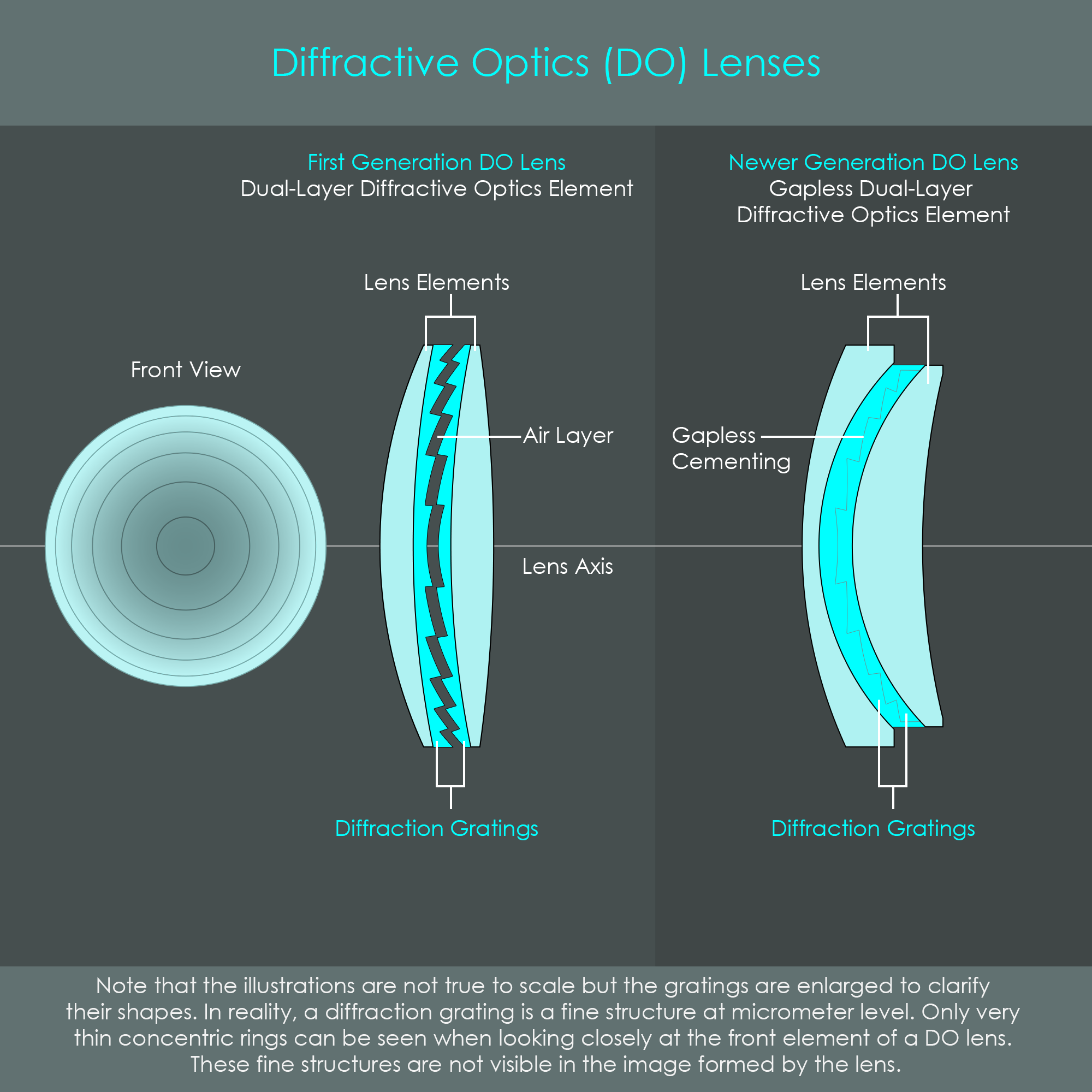
Canon's Diffractive Optics (DO) lenses are specially developed lenses that have a sawblade-like diffraction grating (blazed grating) integrated into one of their lens elements. A diffraction grating redirects rays of light by diffraction rather than refraction. The advantage of this technology is that a diffraction grating is usually smaller and lighter than a conventional glass element so that large telephoto lenses can be designed more compactly. In addition, a DO lens element can be used to reduce color defects (chromatic aberration) produced by other optical elements.
The structure of a diffraction grating can be seen when looking very closely through the front element of a DO lens. It can be seen that one lens element (usually one close to the front of the lens) has fine concentric rings that are caused by the jagged geometry of the gratings.
With their release of the Canon EF 400mm F4 DO IS USM compact super telephoto lens in 2001, Canon was the first manufacturer to incorporate a DO lens element in a photographic lens. This first generation DO lens was separated by a tiny air gap that was the cause of some flare when pointing the camera directly at bright lights. This problem was solved in 2015 when Canon released the EF 400mm f/4 DO IS II USM compact super telephoto lens that had a newly developed gapless DO lens element integrated. Canon's Diffractive Optics lenses have traditionally been labeled with the letters DO in their name or with the term Diffractive Optics printed on the barrel. In addition, DO lenses have been marked with a green ring around the front of the lens barrel. However, Canon broke with this tradition with the introduction of the RF 600mm F11 IS STM and the RF 800mm F11 IS STM super telephoto lenses in 2020. Both of these include DO elements but do not have a green ring.
There are other types of lens shapes such as cylindrical lenses, spherocylindrical or toric lenses. However, these are hardly ever used in photographic lenses and will therefore not be discussed further.
The manufacturing of lens elements relies on various high-precision production techniques that are chosen depending on lens size, shape, and material. In addition, each lens element undergoes numerous individual processing steps until the surfaces are perfectly clear. This paragraph is a short presentation of the most common lens manufacturing technologies.
The traditional manufacturing of spherical lens elements starts with a sheet of optical glass that is slightly thicker than the final lens element. From this sheet, disc-shaped blanks are sawn out with a milling machine. An optional step heats up these flat discs and press-molds them into the approximate shape of the final lens element. If press-molding is used, a process called annealing must follow where the hot lens blanks are allowed to gradually cool down in a very controlled and slow way. This is done to remove internal stresses that build up inside the glass.
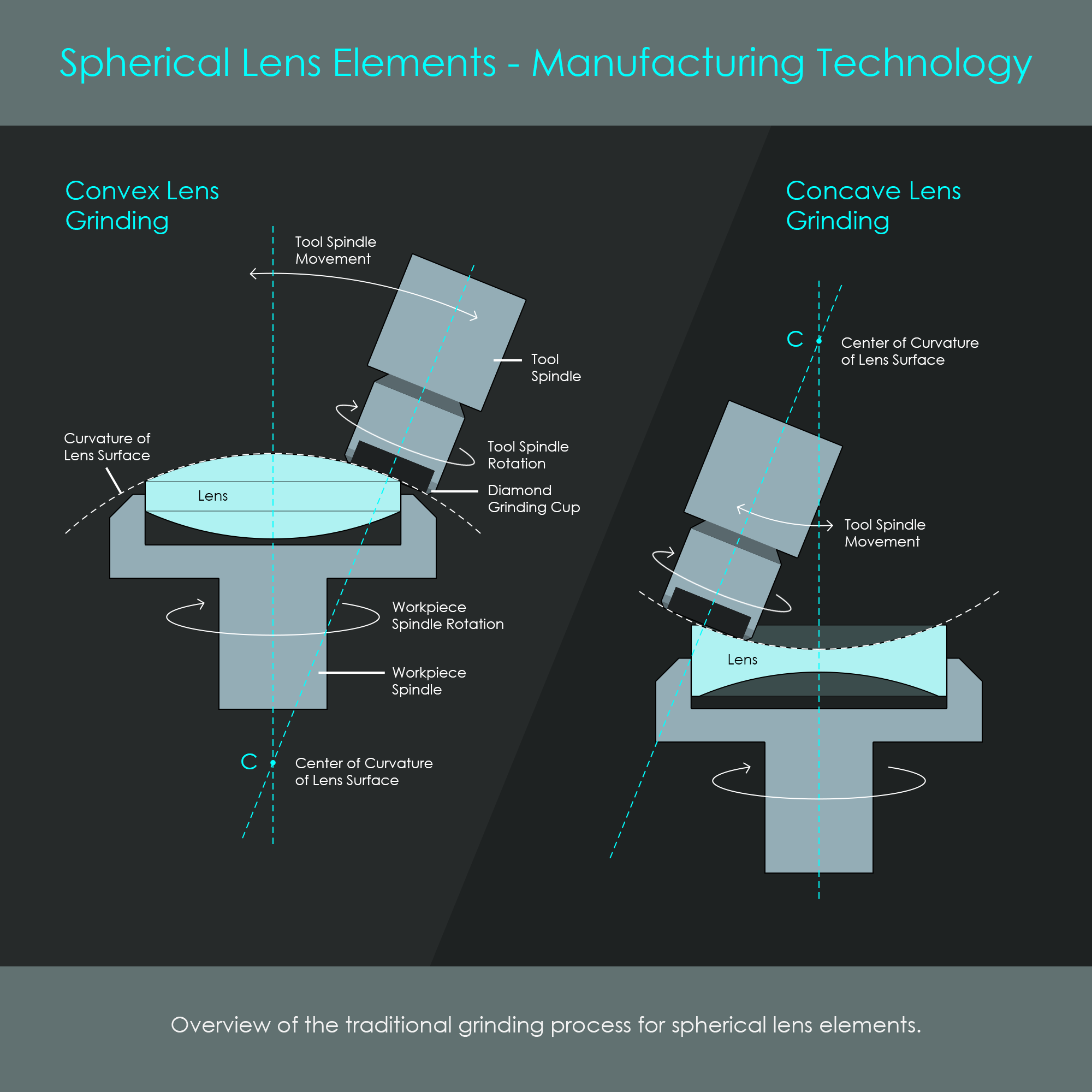
These lens blanks are clamped into the spindle of a specialized grinding machine, and the spherical lens surface is shaped by a grinding tool that uses diamond microparticles. A coarse grinding step forms the rough surface geometry while a fine grinding step optimizes the curvature of the surface. The grinding steps are followed by polishing the lens surfaces, a process that can take several hours for each surface. It is only after polishing when the lens surfaces have reached their specified spherical shapes with sub-micrometer precision. In addition, only polished lens surfaces are perfectly transparent. After that, the lens elements are cleaned and inspected thoroughly using specialized optical equipment. Another important step is the centering of optical elements so that the optical axis is precisely running though the center of the lens element. The periphery of the lens element is cut down to the specified diameter of the lens so that its center coincides with the optical axis. Some additional steps include the application of anti-reflective coatings, beveling, and blackening the edges. Regular cleaning between these steps ensures that the lens surface remains free of particles. Although the production line uses computer-controlled procedures, the manufacturing of lens elements is still a very labor-intensive task.
The complex shapes of aspheric surfaces require some very customized manufacturing techniques to create the desired surface geometries. As of 2024, Canon uses four different technologies to shape these highly specialized lenses.
With this procedure, CNC milling is used to grind the intended surface. A glass blank is inserted into a workpiece spindle. The spindle is rotated, and another spindle with a fast moving diamond grinding head is slowly moving along a lens-specific grinding path. After coarse grinding the process typically involves scanning the surface coordinates via a computer navigated probing system. After the surface has been verified to be correctly shaped, fine grinding and polishing are performed. Final steps include coating, beveling, and blackening the edges, and are similar to traditional lens treatments. Grinding and polishing aspheric lens elements is a very time-consuming and therefore very expensive manufacturing method.
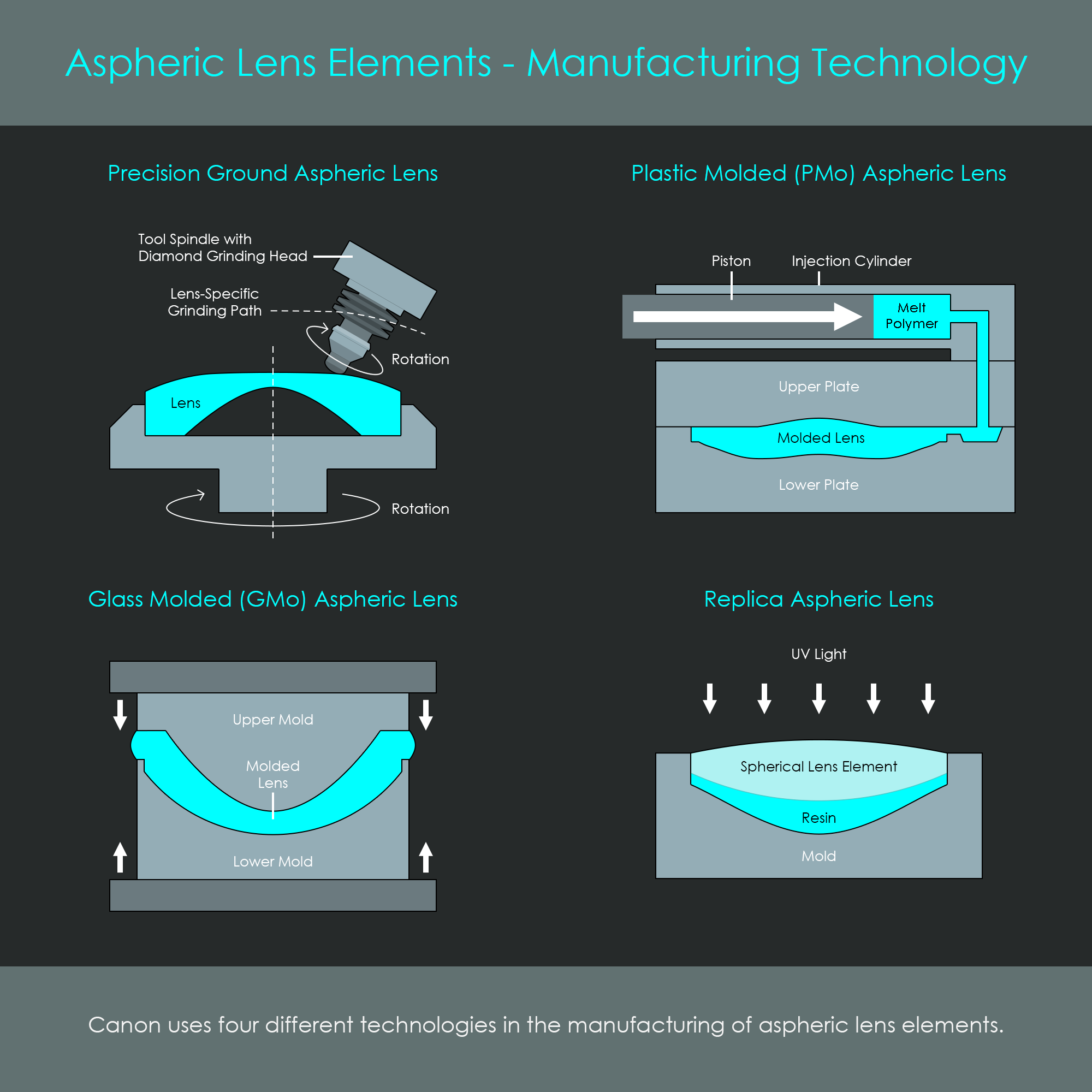
This manufacturing technology is also referred to as injection molding. Two mold plates are pressed against each other. A cavity with an extremely smooth surface finish has the shape of the desired lens element. Optical grade plastic – often highly transparent polymer – is melted. Under the high-pressure force of the injection cylinder's piston, the melted material is injected into the mold cavity through a nozzle. This completely fills the mold and immediately gives the lens element its final shape. Injection molding carries the risk of visible defects in the final product, such as the formation of air pockets or streaks. The application of precise temperature regulation including well defined heating and cooling procedures is the key to prevent such defects from ruining the lens element. After cooling and solidification in the cavity, the mold plates open, and an ejection mechanism releases the lens elements. The molded lens is then polished to optimize the clear surface, and treated with edge blackening and anti-reflective coatings. As the optical performance of some polymers is almost comparable to that of optical glasses, plastic-molded aspheric lens elements offer a low-cost option with a high level of freedom for optical design.
With this processing technique, aspheric lens elements are formed using heat and pressure. The press consists of two mold halves that have the exact surface curvatures of the final lens element, and an extremely smooth finish. The two molds are preheated, and a preformed gob of glass is inserted into the lower mold, which is then pressed together with the upper mold. The formable glass takes the desired shape of the lens element, which is allowed to cool down, and is then removed from the press. Polishing the surface ensures high surface transparency. Final processing steps include coating, beveling, and edge blackening.
An aspheric lens element can be composed of two different parts that are fused together. Liquid optical resin is poured into a mold that is shaped like the aspheric surface. Then, a spherical lens element is pressed into the mold so that the optical resin completely covers the lower lens surface. While still in the mold, the liquid resin is exposed to UV light through the lens. This hardens the resin, and forms a permanent bond with the spherical lens. The resulting optical element now has an aspheric surface. This is another very cost-effective manufacturing technology, and it takes advantage from the fact that most aspheric lens elements have one aspheric surface only. The resin surface of the lens is polished, and the unit is then treated with the usual steps, coating, beveling, and edge blackening.
Lens elements are often produced with bevels (also known as chamfers). These do not have any optical purpose, so they are not involved in any image formation process. Bevels are added mostly for protective reasons, but also to increase accuracy for fitting lens elements into lens barrels.
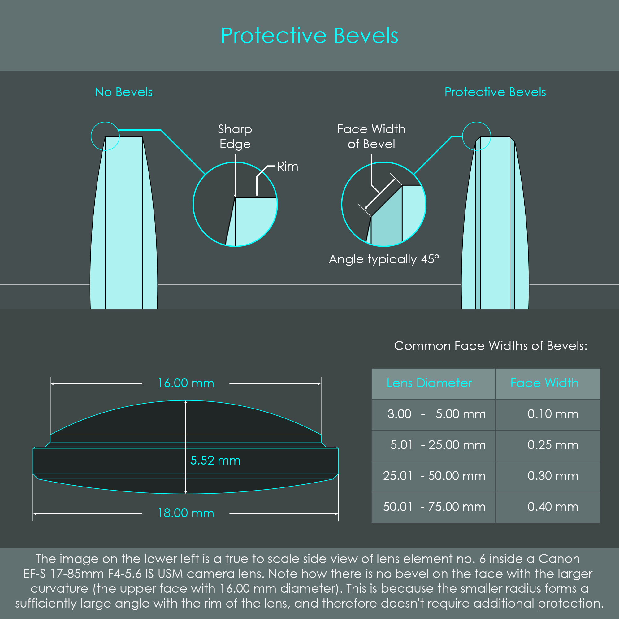
Edges on glass elements can be extremely sharp. This can be hazardous for workers handling the lens elements during production or during assembly of the camera lens. Sharp edges can also be very fragile. This may lead to chip-off during polishing where larger parts might break off an edge, ruining a lens element.
Protective bevels are used to remove sharp edges and therefore increase handling safety and production reliability. When an edge is beveled, some material is taken away to create a slope. This removes one sharp angle and replaces it with two more obtuse angles.
When a lens element has a very small radius of curvature so that the edge of the lens forms a sufficiently large angle with the rim of the lens, a protective bevel is not required. Another exception is that very small lens elements with diameters of 3.00 mm or smaller do not get their edges beveled due to an increased risk of chipping the edge during the process. For all other lens elements, protective bevels are usually applied with various face widths depending on the diameter of the lens. Some common bevel face widths are provided in the table on the lower right of the illustration about protective bevels.
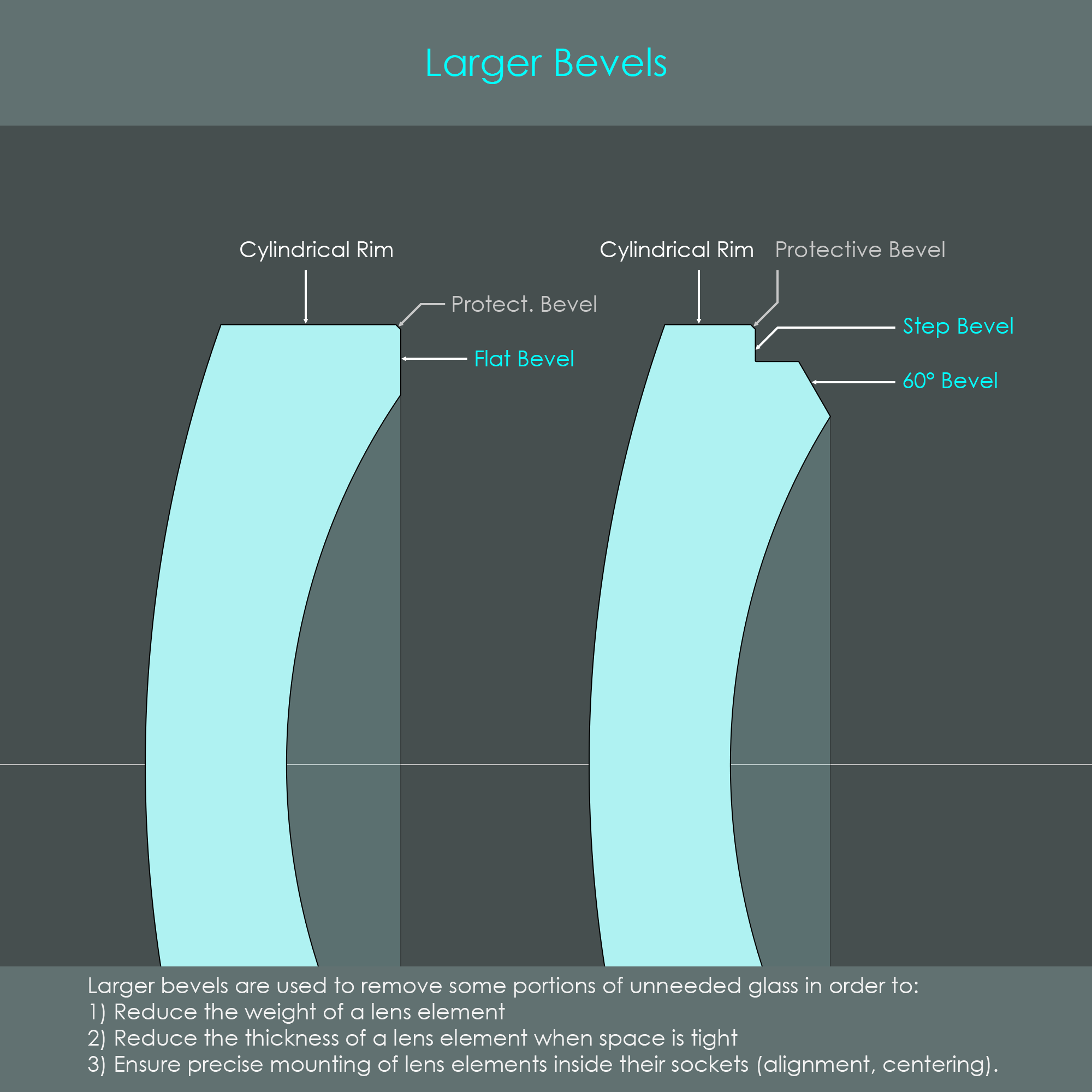
Another procedure often applied to lens elements is to cut larger bevels into edges. Of course, larger bevels can only be cut into regions that are not required for the optical functionality of the lens. This removes larger amounts of material and mainly serves the following purposes:
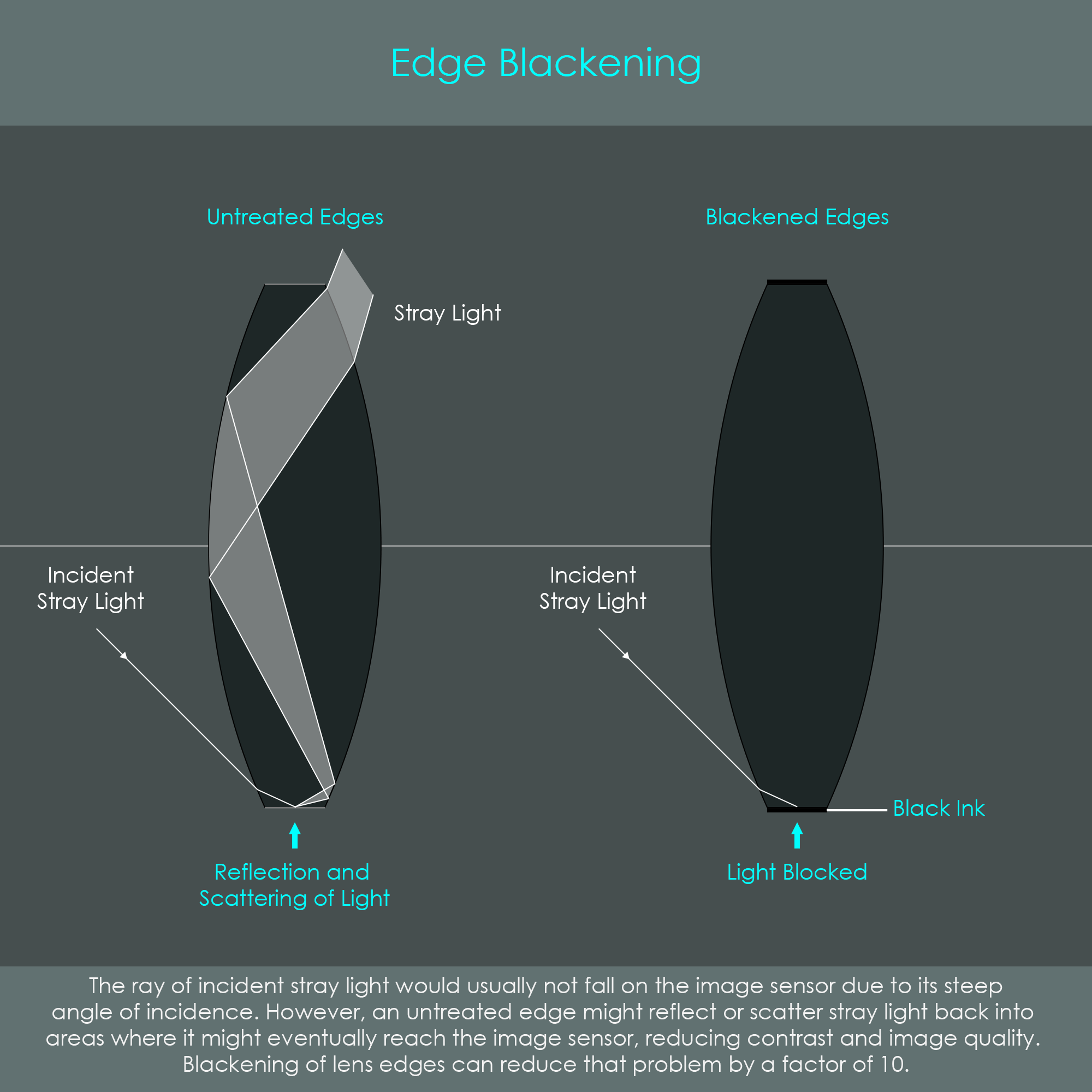
When lens elements are produced, their main surfaces are highly polished but their edges are usually ground to a matte finish. With untreated lens edges, stray light can become a limiting factor in overall imaging performance of an optical system. Stray light can enter an optical system from outside at a path that was not intended in the design of the system, and that scatters off of the edges of an optical or mechanical component and reaches the camera's image sensor in the form of noise (rather than signal).
One very common method to successfully reduce stray light within an optical system involves the application of a light-absorbing layer to the circumferential edges of all optical components, outside their optically effective areas. This process is called blackening and it can reduce edge-induced stray light by a factor of 10 which significantly increases contrast in the image. The edge treatment may include:
These methods usually do not significantly add to the diameter of the lens, so that lens elements can still be perfectly assembled into the lens sockets.
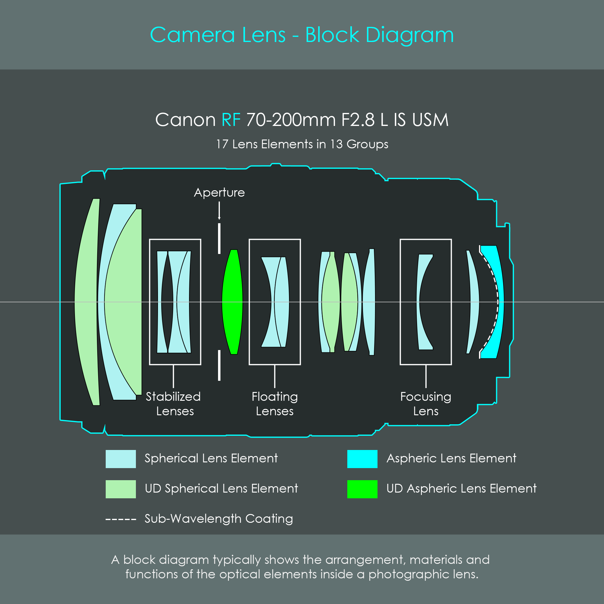
A lens block diagram - also referred to as lens element diagram - provides information on the basic optical design of a camera lens. It includes the geometry and location of all optical glass elements and adds labels to lens elements with special roles such as the focusing elements, floating elements, as well as image stabilized elements. In addition, lens block diagrams often use colors to distinguish spherical lens elements from aspheric ones, to show ultra-low dispersion (UD) glass elements, or to highlight special lens coatings. In addition, lens block diagrams show the location of the aperture diaphragm, and the position of a secondary aperture diaphragm, if available (some lenses only). For zoom lenses, some lens block diagrams show two or three configurations of the same lens with all lens elements at different positions depending on the focal length.
All that information can be enormously useful for people who need to repair a lens or clean lens elements on the inside. Once a lens has been completely disassembled, it can be challenging to put everything back together in the correct order and orientation. The diagram can help to verify whether a glass element has been reinstalled with the surfaces pointing into the right directions. In addition, the diagram can also help to establish a disassembly strategy: If there are fewer lens elements to dismantle from the front of the barrel to access the diaphragm unit, it might be best to start at the front element. The lens block diagram can help to focus more on the repair and less on the documentation of each step.
Canon's lens block diagrams or lens specifications usually include information on the number of lens elements and the number of lens groups. Lens elements are the individual pieces of glass inside the lens system. Lens groups are pairs of lens elements that are cemented together and are therefore counted as one group. It is typically the second element within a group that specifically corrects some aberrations produced by the first element. Single lens elements that are not cemented to another element also count as one group.
The Canon RF 70-200mm F2.8 L IS USM lens has 17 lens elements divided into 13 groups. This tells that there are four doublet lenses installed that have corrective elements cemented to the first element.
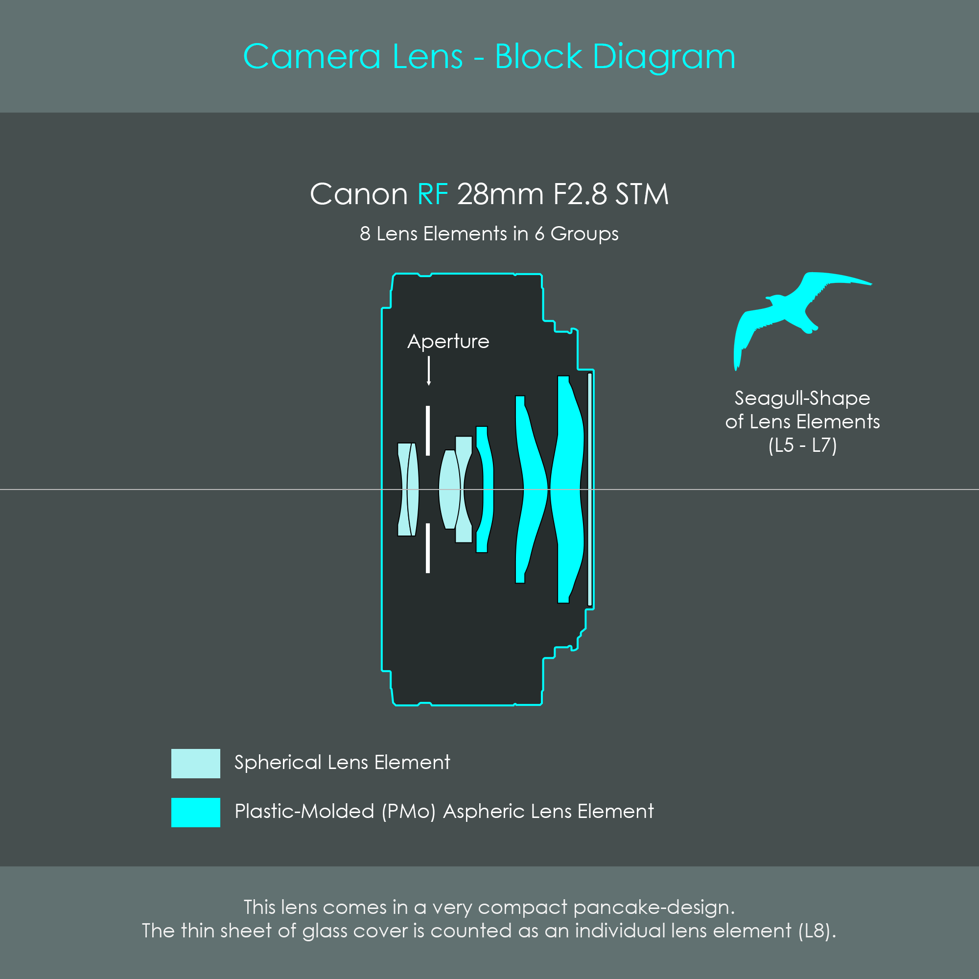
The second diagram shows the Canon RF 28mm F2.8 STM lens. Due to its ultra-compact and thin design, this lens is also called a pancake lens. Looking at this block diagram, it becomes immediately apparent that some lens elements do not have traditional spherical surfaces. These are plastic-molded aspherical lens elements. The cross-sectional shape of these specially molded lens elements is reminiscent of a flying seagull, and therefore these lens elements are also called seagull lens elements. Some camera hardware pages advertise seagull lens elements as a completely new technology, but they are technically aspherical lens elements. It is only the shape of these lens elements that is rather unconventional.
Seagull lenses help reduce some optical aberrations, but they are particularly useful to achieve small lens designs. These shapes have already been designed into smartphone camera lenses for some time, and now they have found their way into Canon's RF lenses.