An interchangeable photographic lens may have different kinds of mount systems with different purposes.
The history of photography goes back roughly 200 years. Over that time, manufacturers have always improved usability of their systems and tried to set up mechanical standards. Just as the evolution of camera systems there has also been a constant development of lens mounts. Some of the first mechanisms used to attach lenses to camera bodies was the screw-type mount where a simple external thread on the lens-side engages with an internal thread on the camera side. Later, manufacturers used breech-lock mounts where the lens is inserted into the camera and a locking ring at the rear of the lens is turned until the lens was securely fastened to the camera. The locking ring is designed so that it engages with some tabs on the camera-side, and by turning the ring the lens is pressed against the camera. The ring is kept in its locked position by friction, hence the breech-lock mount is also called friction-lock mount. Another mount system that was developed pretty early in photographic history but that is still the most popular mounting systems even with modern camera systems is the bayonet mount. When a camera system uses a bayonet-type mount system, the lens is inserted into the camera and then turned so that tabs on the lens mount engage with recesses in the camera. The bayonet system is today's standard mechanism as it precisely aligns mechanical and electrical features between the camera lens and body.
In 1946, Canon introduced their first interchangeable lens called the Serenar 50mm F3.5. Since that date, Canon has introduced eight lens mount types:
In 1987, Canon introduced their Electro-Optical System (EOS) line of cameras. At that time, this was a revolutionary step forward as this camera system came with a microprocessor to control photographic settings and the lens. Since that date, Canon's digital camera systems all use the bayonet-type lens mount, so only these will be covered in this section. Let's take a closer look at the camera-side of lens mount systems:
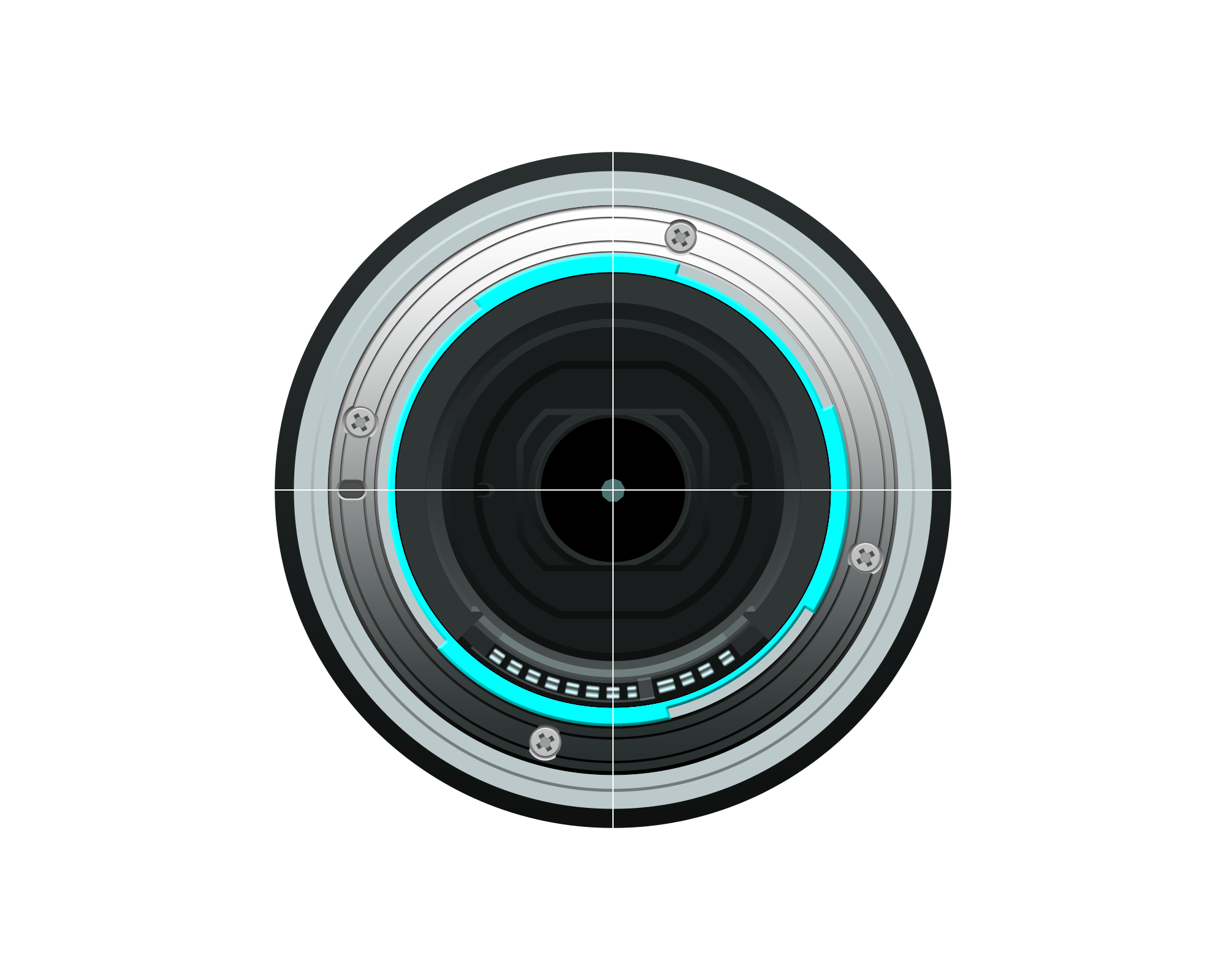
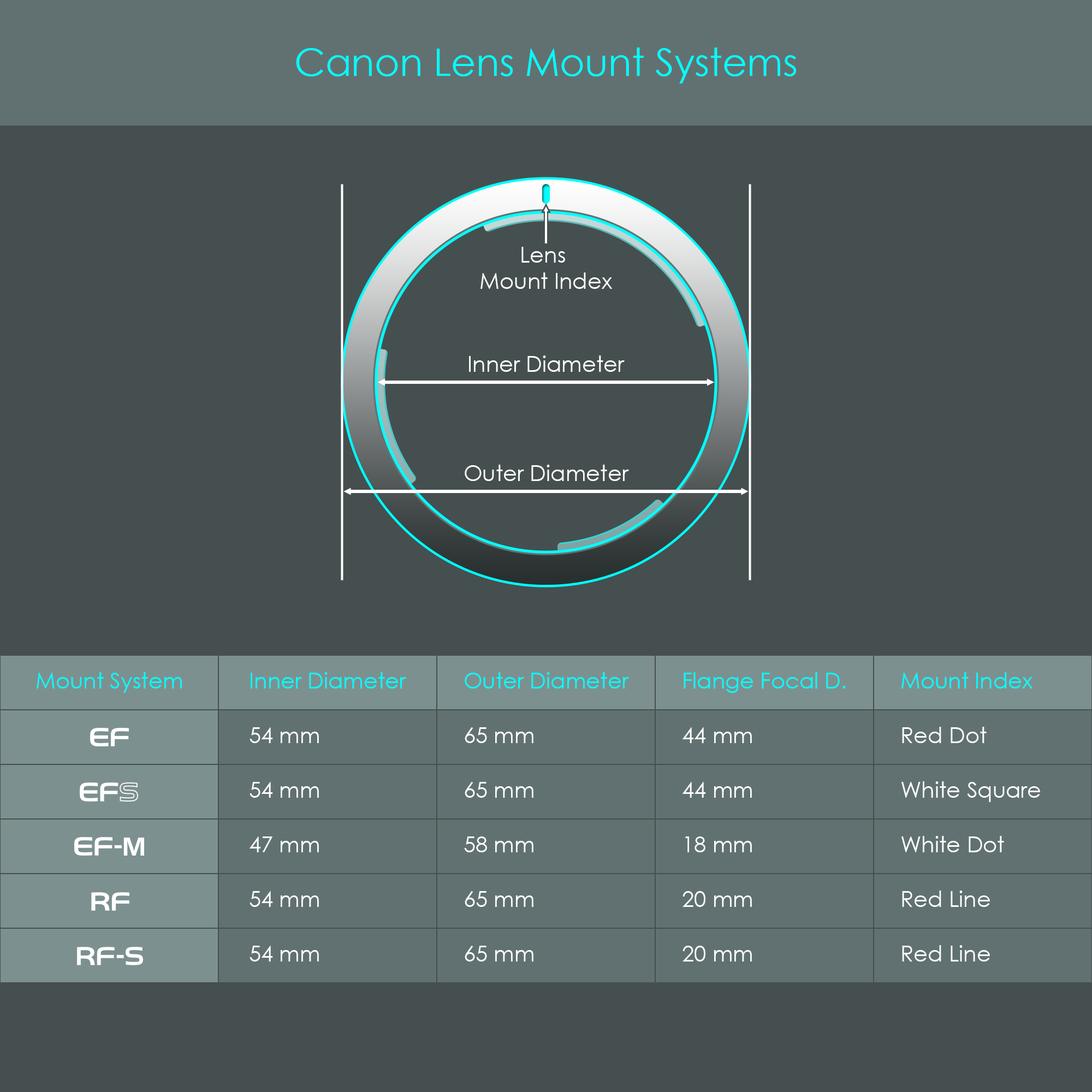
The camera-sided fixture of a bayonet mount consists of a metal attachment ring that is integrated into the front of the camera body. The inside of that ring opens up the view of the camera's image sensor, or the mirror assembly, if looking at a DSLR camera. The front face of the attachment ring shows a lens mount index that indicates how the has to be positioned for the lens to be accepted by the camera-sided mount (there is also a mount index on the lens). The attachment ring has three mounting tabs protruding to the inside. Their asymmetrical geometry is designed so that a lens can only be attached in one position, if a user would ignore the lens mount index. Once the lens-sided mount has been slid into the camera-sided mount, the lens is turned clockwise (seen from the front of the camera where the lens is attached) about a quarter of a turn until the locking spring secures the lens in place via a locking pin that engages with a corresponding hole on the lens. This is heard by a clicking sound and prevents the lens from turning back into the open position. The lower part of the camera-sided mount is used for the electronic interface that consists of eight to twelve contact pins, depending on the mount type. Once a lens is attached and has been turned into the locked position, these pins touch contact pads on the lens-sided mount and establish a mechanical and electronic connection for power supply and data transfer.
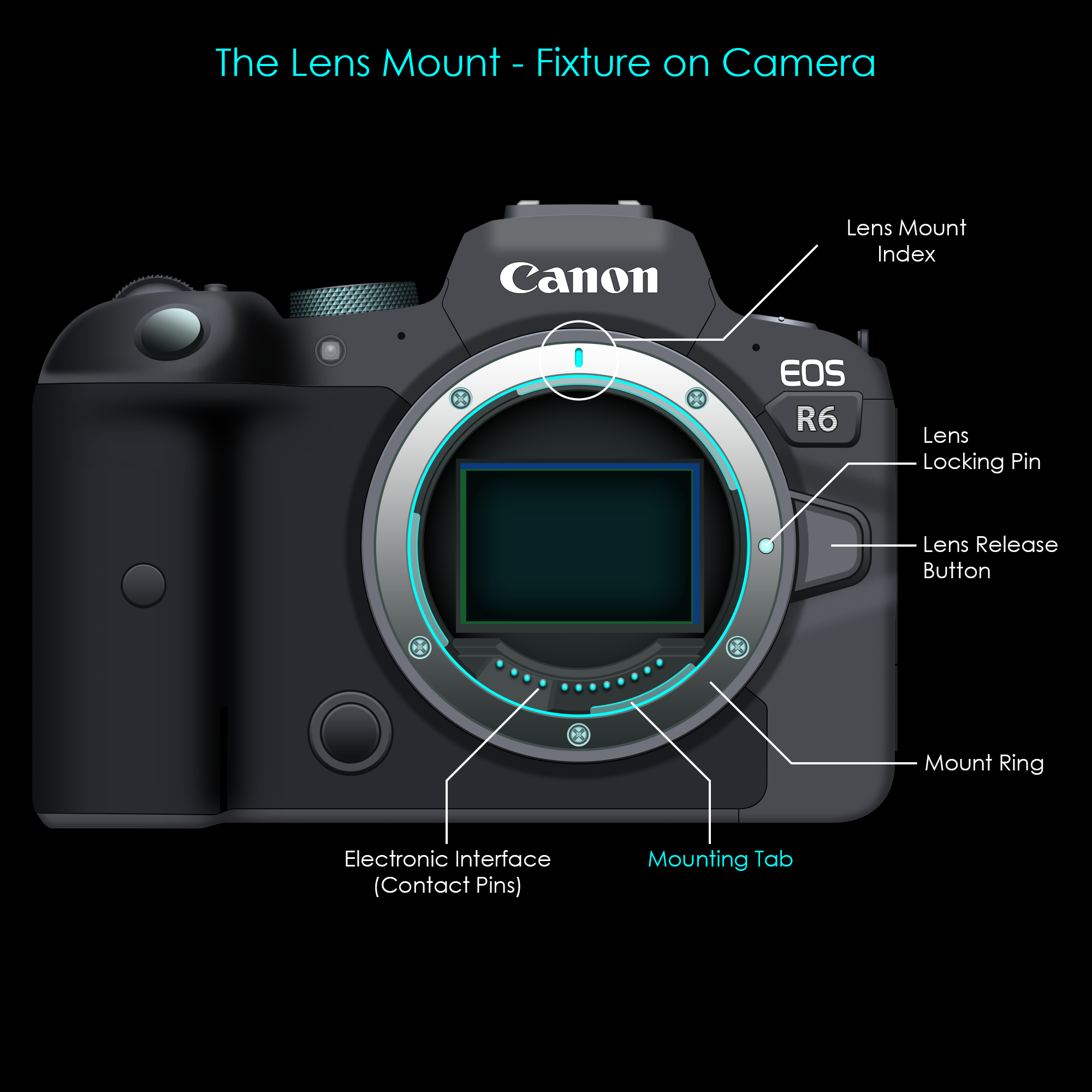
To release a lens from a camera body, there is a lens release button next to the camera-sided mount. While that button is pressed, the locking pin is retracted and no longer keeps the lens from turning. The lens can then be turned counterclockwise (seen from the front of the camera again) and once it reaches the open position it can be detached from the camera. It is recommended to cover the camera-sided lens mount with a camera body cap as soon as it is opened up to prevent dust and moisture from entering the camera body.
Here are the main lens mount systems that are widely supported by Canon today:
There are adapters that allow some compatibility across platforms (for example to mount an EF lens to an R-mount camera, but not all combinations are possible. For more information on the lens mount compatibility, check out the corresponding section further below.
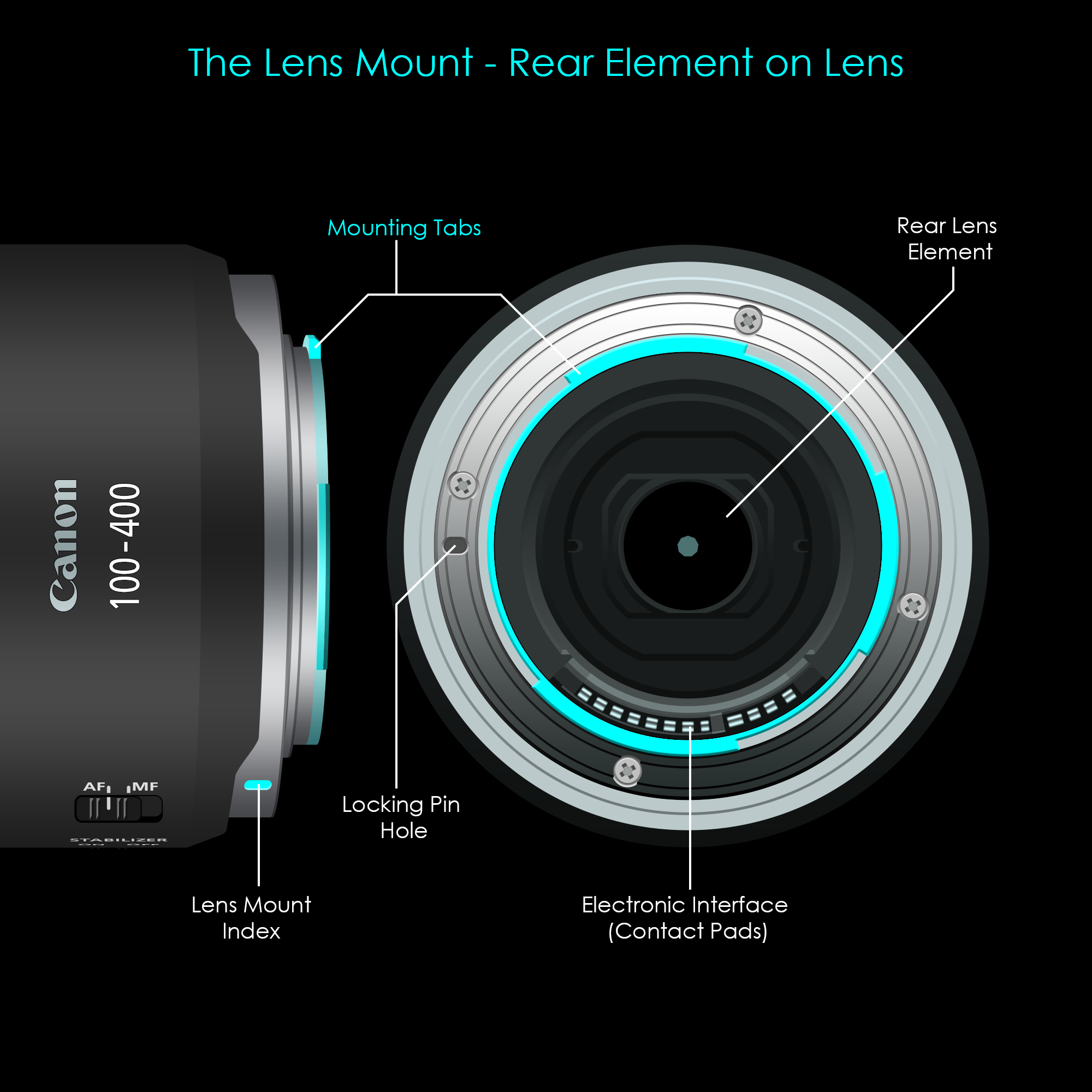
The lens-sided part of a lens mount is the mechanical and electronic counterpart to the camera's attachment ring. The lens has a cylindrical rear geometry so that the lens perfectly fits inside the camera's mounting fixture. A mount index on the side of the lens barrel indicates how the lens must be positioned in order to be accepted by the camera body. The lens-sided mount also has three mounting tabs that are pointing outward. These mounting tabs are arranged so that they perfectly slide through the gaps between the camera-sided tabs. Once the lens is completely inserted into the mount, the lens is turned into the locked position. This slides the lens-sided tabs behind the camera-sided tabs, securely holding the lens in place. All tabs are machined so precisely that there is no room for movement which is an important requirement for a precision tool. The locking pin hole on the back of the lens is required for the locking pin of the camera to engage with the lens, and to protect it from loosening up. Finally, all modern camera lenses have electronic pads on their back element that connects to the electronic pins of the camera body. You can read more about the electronic interface in the chapter about lens electronics.
Here are the (lens-sided) mount systems that are still supported by Canon today:
It was already explained that some lens types can only be used on certain camera systems. What lens types and camera systems are actually compatible is summarized in the compatibility chart.
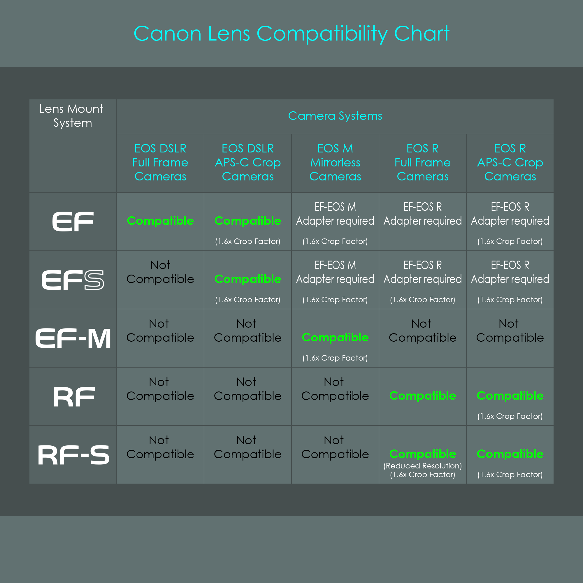
Canon EOS R full frame mirrorless cameras have an electronic feature installed that ensures compatibility with RF-S lenses (the ones with a smaller image circle). Attaching an APS-C lens to a full frame sensor does not cover the entire sensor with an image, leading to completely black outer portions of an image. To prevent these black edges from appearing on the final image, Canon has implemented an automatic adjustment: Once a Canon full frame EOS R camera detects an RF-S lens attached to the camera (or an EF-S lens attached via an adapter) it automatically switches to a cropped mode, reducing the active area on the image sensor to the size of an APS-C sensor. This again reduces the field of view so that a 1.6x crop factor creates the impression of an increased focal length. The difference compared to a real APS-C sensor is that this electronic cropping reduces the image sensor's resolution because only a smaller area is used to record the image. Besides the reduced image resolution this is a nice feature to increase cross-compatibility between platforms.
The following paragraphs are going to explain some of the major differences between Canon's bayonet mount types. There are different attachment ring diameters, different flange geometries, and different flange focal distances.
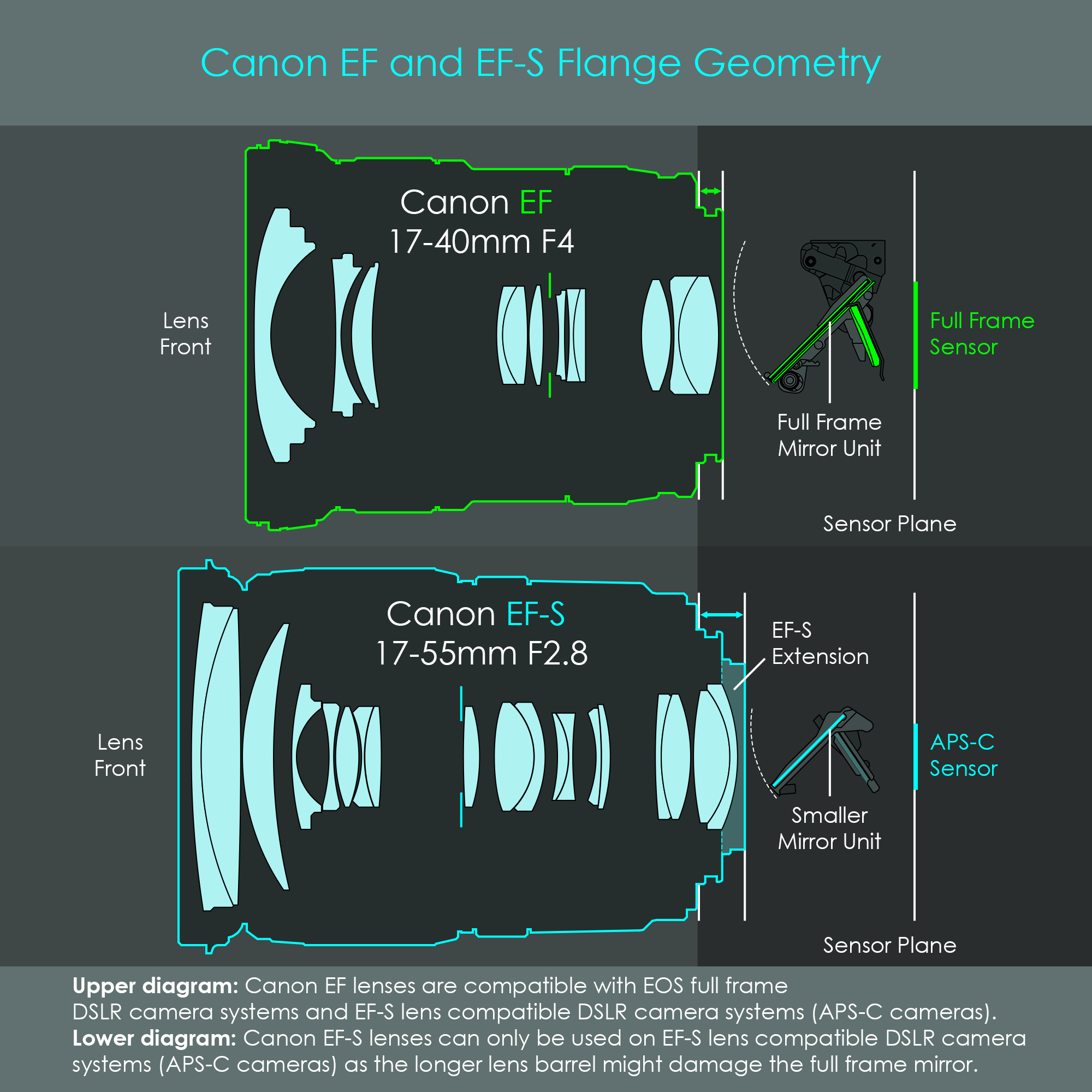
Canon's EF-S lenses have an extension on their rear part of the barrel that protrudes further into the camera body than an EF lens. This is only possible because EF-S lenses are designed for APS-C DSLR cameras that have a smaller image sensor but also a smaller reflex mirror. The smaller dimensions of the mirror ensures that it doesn't collide with the extension of the EF-S lens when it is folded up during a photograph. This is the main reason why an EF-S lens is not compatible with EOS full frame DSLR cameras that have a larger reflex mirror.
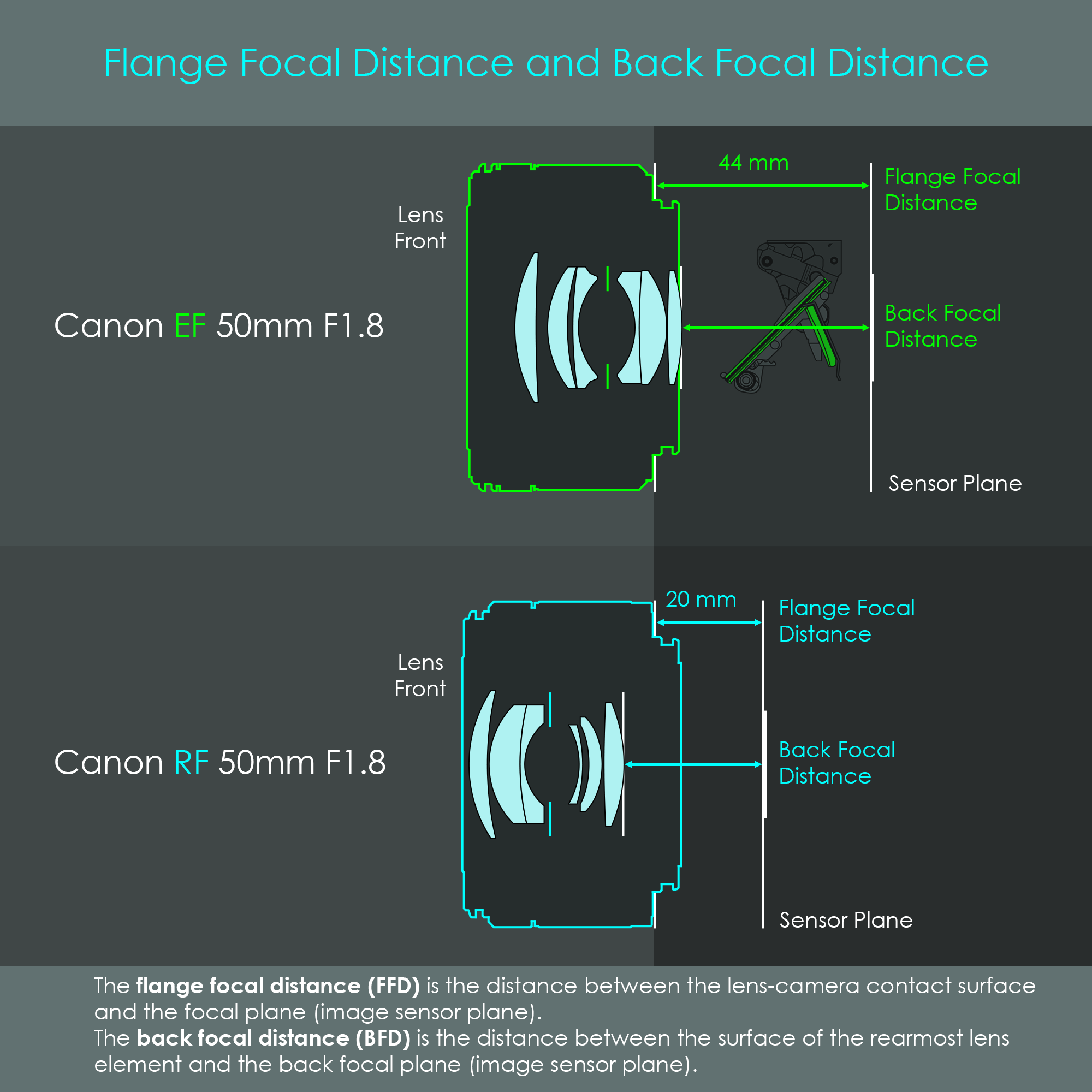
For an interchangeable lens camera, the flange focal distance (FFD), also referred to as flange back distance (FBD) or flange focal length (FFL) of a lens mount system is the distance between the mounting flange (the surface where the camera-sided attachment ring touches the lens-sided attachment surface) and the image sensor plane. Canon's new RF mount system uses a significantly shorter flange focal distance than the EF mount system, 20 mm instead of 44 mm, this means that the RF mount is installed just 20 mm from the image sensor. This not only provides a more compact camera design but also increases compatibility with other longer FFD lenses because an adapter can simply adjust for the required distance. In addition, lens developers claim that a shorter flange focal distance would increase their flexibility in lens design, ultimately leading to higher quality lenses. In lens design and in the production of photographic lenses and camera systems, the flange focal distance is one of the most important variables. Even a tiny inaccuracy in the range of 0.01 mm can already cause problems such as an inability to reach infinity focus, or a significantly degrading image quality of the lens, especially near the edges and corners of the image.
The back focal distance (BFD) is a different measurement. Back focal distance describes the distance between the surface of the rearmost lens element to the image sensor plane. This distance is equally relevant in the design and production of lenses. Comparing both 50 mm lenses of the EF and RF mount types, the back focal distance is almost identical. However, there are RF lenses with shorter back focal distances.
Lens mount adapters are a useful tool to attach lens types to camera systems that would normally not fit together. A lens mount adapter not only establishes a structural connection between the lens and the camera body (including the security lock mechanism with locking pin and release button), but also enables the electrical communication between the lens and camera. Furthermore, an adapter serves the purpose of positioning the lens at the exact flange focal distance that is required for that lens mount type in order to produce a properly focused image. In general, there are two kinds of lens mount adapters:
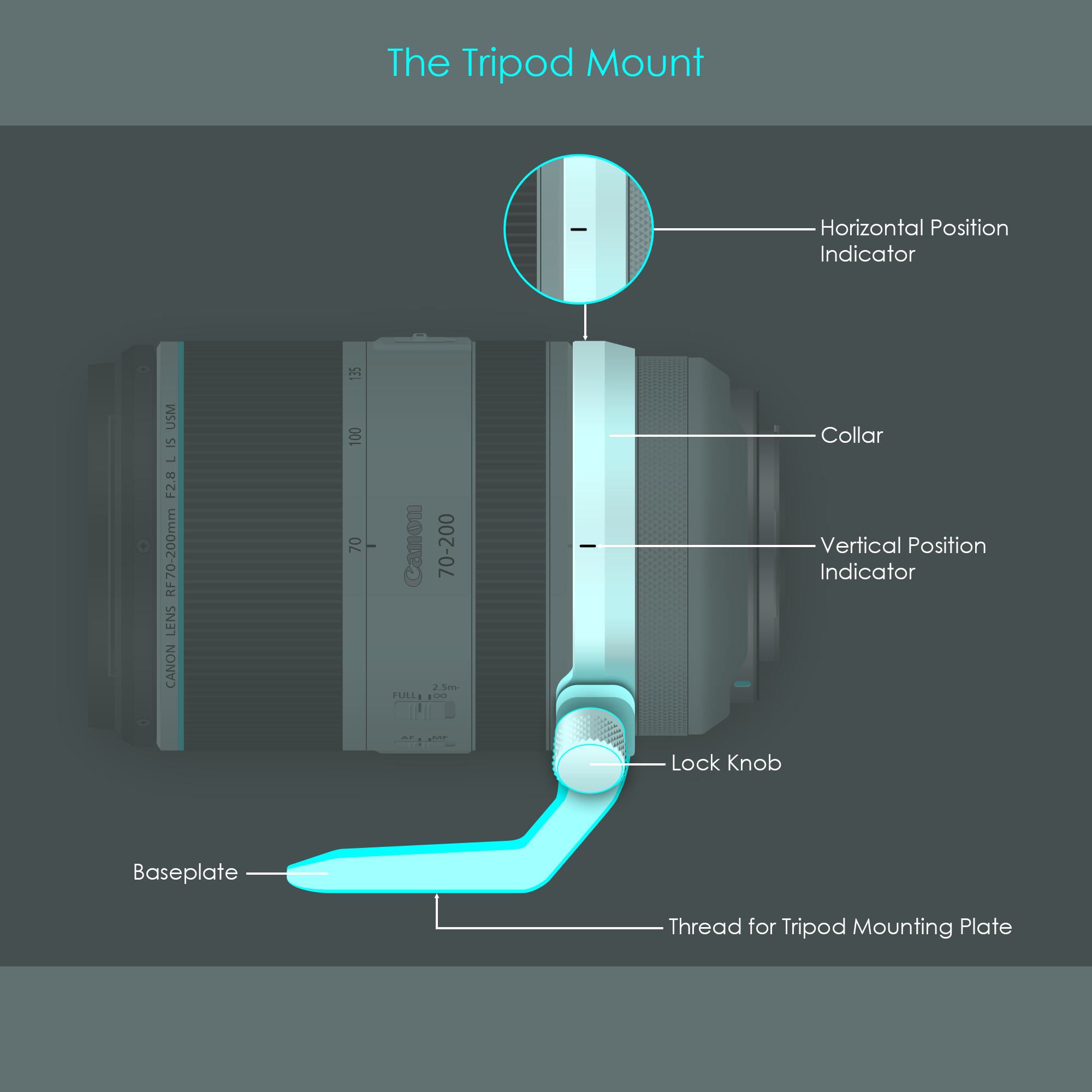
A tripod mount is an optional part that can be attached to larger camera lenses. Their purpose is to attach the lens to a tripod. When a long and heavy lenses is mounted to a camera it is usually not recommended to attach the tripod to the camera's integrated tripod mount. The weight of the lens exerts a lot of torque on the tripod head, and also the entire mount system. In that case, standard tripod heads simply give in to the high force and bend downwards. Using a tripod mount collar ring on a heavy lens ensures that the entire unit is balanced more around its center of gravity, not exerting an excessive amount of torque on the tripod head.
The tripod mount collar can be loosened up so that the lens and camera unit can be rotated into vertical or horizontal positions, or it can be taken off completely if not used all the time.
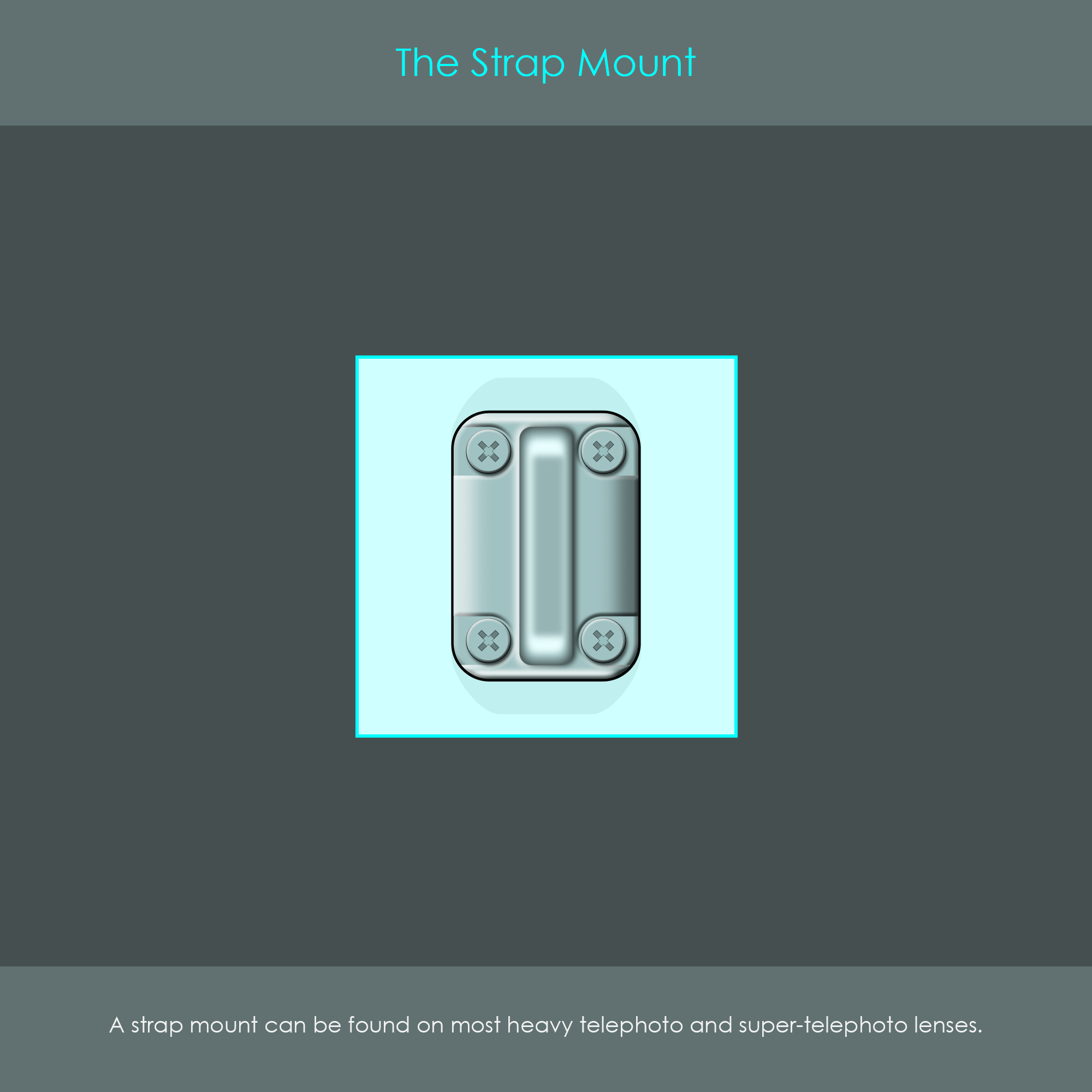
Some larger and heavier telephoto and super-telephoto lenses are equipped with a metal strap mount that is permanently screwed to the lens barrel. This type of mount can be used to thread a carrying strap through the mounting hole.
A description of the front element filter mount is given in the chapter The Lens Barrel, and a description of all filter mounts is given in the chapter Filter Systems