Strictly speaking, every lens can be regarded as a special purpose lens. The special purpose of a wide-angle lens, for instance, is to cover particularly large angles of field. By contrast, the purpose of a telephoto lens is to cover particularly narrow angles of field. For the sake of a clear definition, however, this chapter regards wide-angle lenses and telephoto lenses only as different options within the focal length spectrum. This chapter presents three lens types that are designed for highly specialized, non-standard or unusual applications regardless of their focal length.
A macro lens is designed with an extremely short focusing distance so that the lens can be moved very closely to the subject and still produce a precisely focused image. This in turn allows a macro lens to project a much larger image of the subject onto the camera's image sensor. This property is what creates ultra-high magnifications of a scene, and therefore macro lenses are typically used to photograph tiny subjects such as insects or botanical structures.
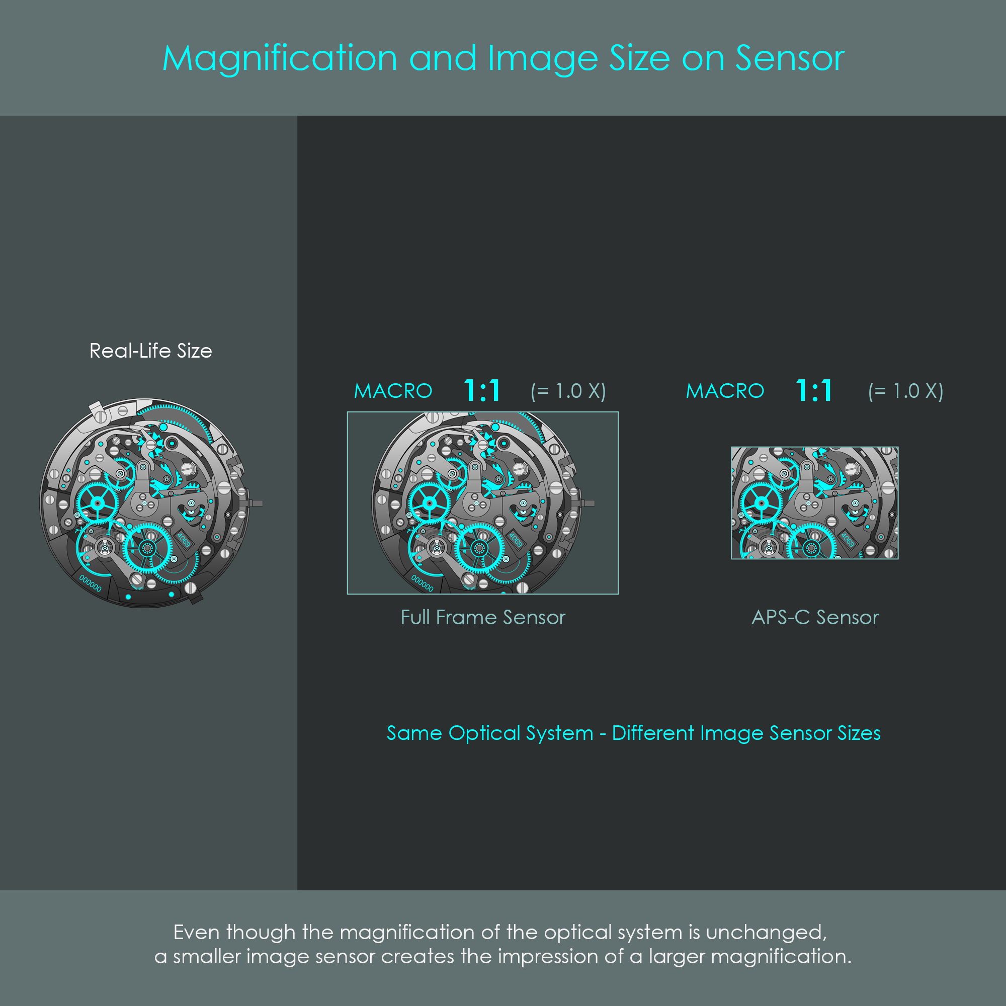
A lens must be capable to produce a reproduction ratio of 1 : 1 in order to be called a true macro lens. A 1 : 1 reproduction ratio means that the lens can form a life-size image on the camera's image sensor that has an identical size as the object. This level of magnification can also be expressed as a magnification of 1X.
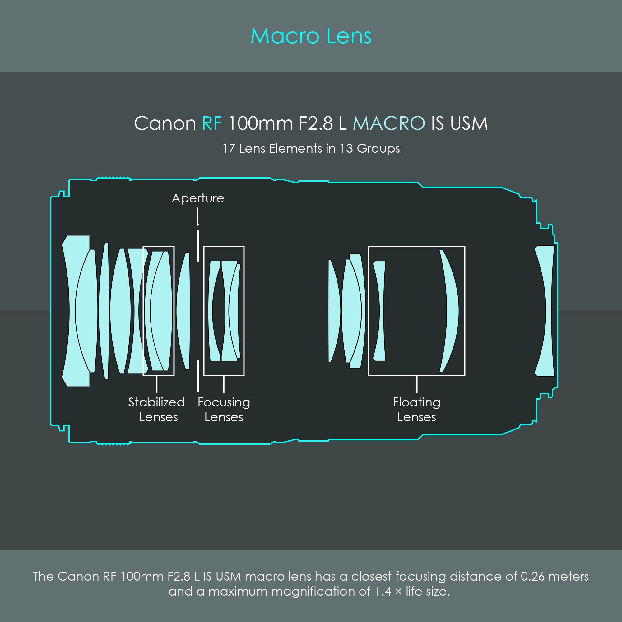
The illustration is a block diagram of the Canon RF 100mm F2.8 L MACRO IS USM lens, a short telephoto macro lens highly valued by professionals for its excellent imaging performance.
Reproduction ratio and magnification describe one and the same concept: They express the relation between the image size and the object size. The only slight difference is that the reproduction ratio is expressed as a relation whereas magnification is expressed as a factor.
In macro photography, it is relevant to know the largest image size a particular lens can form. The further away an object is from the lens, the smaller is the image formed on the sensor. Therefore, the largest image is formed when an object is placed at the minimum focusing position. For that reason, lens manufacturers usually specify the maximum magnification of a lens.
This is expressed as image size : object size. For example, a reproduction ratio of 1 : 4 shows that the largest possible image the lens can form is still four times smaller than the object. This is a fairly common reproduction ratio for non-macro lenses. On the contrary, a reproduction ratio of 1 : 1 shows that the largest possible image is identical in size compared to the object. This ratio shows that the lens is a macro lens and that a 2 mm object will be exactly 2 mm on the image sensor (when shot at the minimum focusing distance). A macro lens that can produce an image even twice the size of the object consequently has a reproduction ratio of 2 : 1.
This is expressed as a factor X and indicates how much smaller or larger the image is compared to the real-life object. For example, a magnification of 0.25X expresses the same optical property as a reproduction ratio of 1 : 4. A magnification of 1X indicates that the largest possible image is similar in size than the object. A magnification of 2X is identical with a reproduction ratio of 2 : 1.

The illustration shows how an image height of 60% compared to an object height of 100% results in a magnification of 0.6X. When determining the magnification using the image height and object height, the sign of magnification will indicate whether an image is inverted or upright: A negative magnification indicates that the image will be inverted, whereas a positive magnification indicates the image will be upright. Another way to determine the magnification is to divide the image distance by the object distance.
One misconception in the context of macro photography is that magnification is not a property of a lens itself. In reality, magnification is the result of the overall setup and layout of an optical system consisting of an object, the lens, and an image plane. It was shown that magnification is determined by calculating the ratio between the image height and object height, and no property of the lens is part of the equation. Despite this fact, most lenses are not capable of 1X magnifications which would qualify them as macro lenses. The reason therefore is that most photographic lenses do not offer sufficiently small focusing distances that would be required to form life-size images. True macro lenses are specialized so that they are able to focus at extremely close objects, which automatically creates larger images.
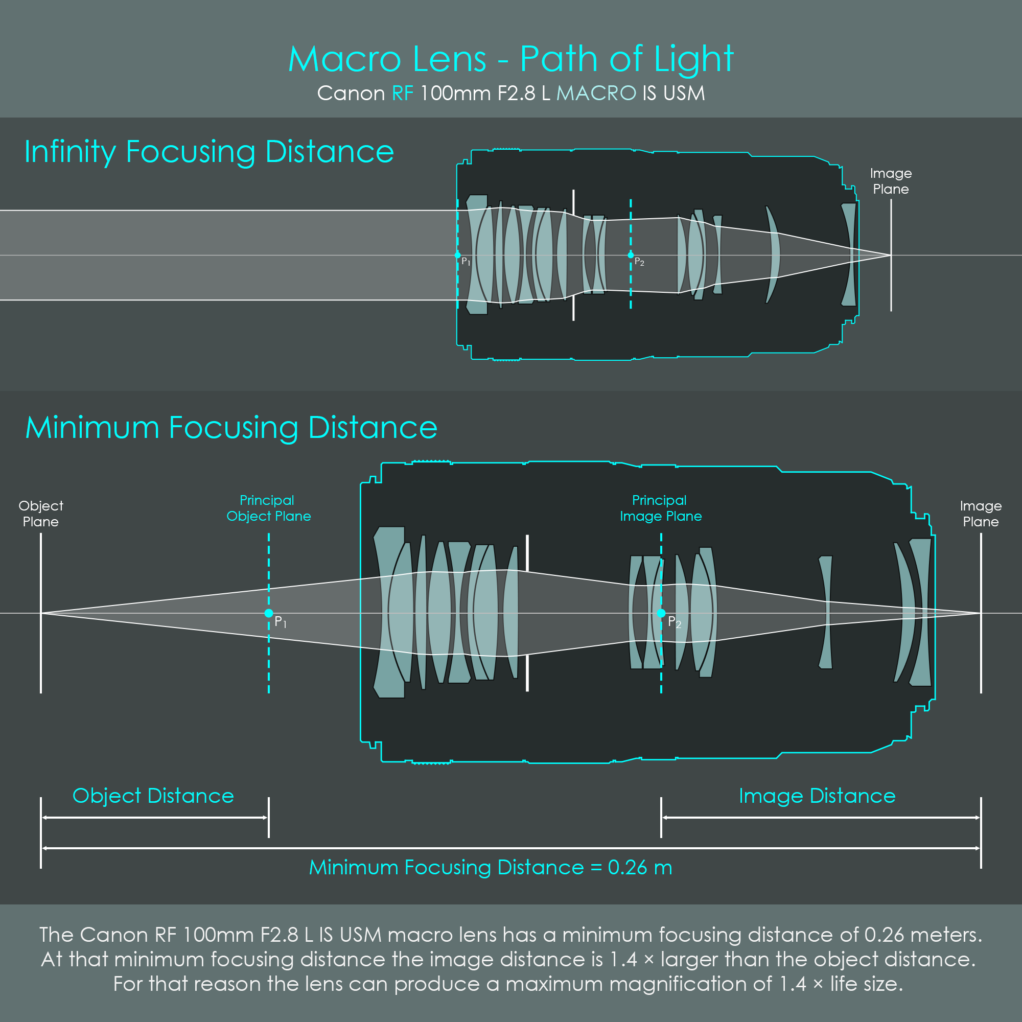
Looking at the Canon RF 100mm F2.8 L MACRO IS USM, this relation between image distance and object distance can be used to geometrically prove the 1.4X maximum magnification the lens offers. At the minimum focusing distance, the image distance is 1.4 times larger than the object distance, resulting in an image height that is 1.4 times larger than the object. As per the definition, this makes the RF lens a true macro lens that can form an image that is 40% larger than the object.
Of course, every macro lens can also focus at farther distances. For example, the Canon RF 100mm F2.8 L MACRO IS USM is not only ideal for macro photography, but due to its focal length it is also an excellent choice for portrait photography.
There are at least two different optical concepts which use the term magnification:
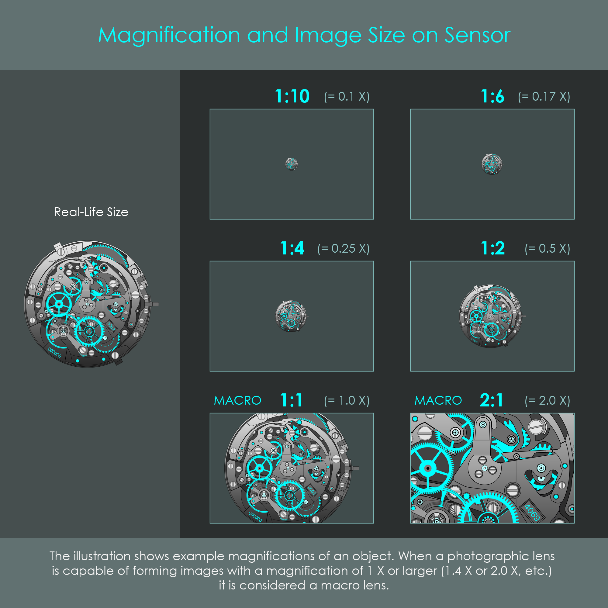
The illustration shows different magnifications and the resulting image sizes on a full frame sensor compared to the object's real-life size. The magnification is expressed in both the reproduction ratio (large labels) as well as the macro magnification (smaller labels in brackets).
The size of the image sensor has an additional effect on the magnification. While the optical system produces an image in accordance with its overall setup (image distance, object distance), it ultimately depends on the image sensor how much of that image is actually recorded to create the final photograph. With an identical optical system, a smaller image sensor will record less of that image. This creates the impression of an even higher magnification, an effect also known as the crop factor. Due to this effect, photographers do not always require a true macro lens to achieve a similar effect. With a smaller image sensor, macro photographs can also be shot with lenses that offer less than 1X macro magnification. Read more about the crop factor in the chapter about lens equivalence.
Macro Designation: Canon labels their macro lenses either with the shortcut MP-E (only one macro lens actually uses that) or MACRO (all other macro lenses) in the lens name or somewhere else on the lens barrel.
Maximum Magnification: The maximum magnification of the lens may sometimes be printed on the lens barrel. If that is not the case, the maximum magnification (X) can almost certainly be found in the technical specifications of the lens.
Minimum Focusing Distance: This information is usually printed on the rear portion of the lens barrel. Also referred to as closest focusing distance. The minimum focusing distance is specified in meters and feet. If not printed on the barrel, it can be found in the technical specifications of the lens.
Below is a list of Canon lenses to compare these values between non-macro and actual macro lenses. Note that the minimum focusing distance is measured between the image plane and the subject, and therefore the actual working distance between the lenses front element and the subject is much smaller.
A tilt-shift – or TS – lens is another extremely specialized lens, and it is clearly not for everyday photography. It combines two separate and rather unique features: A tilt function that rotates the lens plane relative to the image plane, and a shift function that moves the lens parallel to the image plane. Although there are some lenses that offer only one of these functions, Canon always implements both tilt and shift movements in their TS-E lenses.
This chapter presents the mechanical and optical principles that make Canon's tilt-shift lenses work.
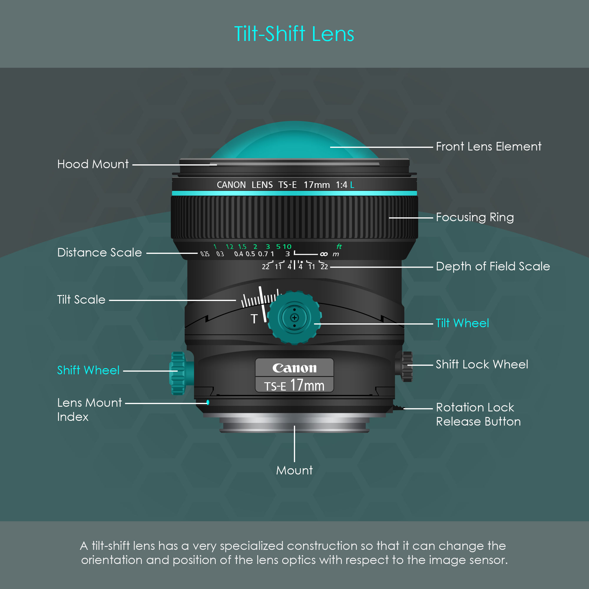
The illustration shows the side view of the Canon TS-E 17mm F4 L lens. TS-E stands for tilt-shift-electronic. As the lens name suggests, this lens is not driven by an autofocus system but it is a manual focus lens. There is also no image stabilization available for tilt-shift lenses.
Taking a look at the control knobs and wheels, these are used independently from each other to either tilt the lens or to shift it. In its default mounting position, shifting can only be performed up and down while tilting can only be performed left and right. The shift lock wheel is tightened by default to prevent the lens from shifting down on its own due to gravity. Therefore, this wheel has to be untightened before shifting the lens, and tightened whenever the lens has been shifted into its desired position. By pressing the rotation lock release button, the entire lens can be rotated 180 degrees around the optical axis, so that tilting and shifting the lens is both possible in every direction. The lens offers tilting angles of ±6.5 degrees and shifting ranges of ±12 mm.
Although this lens has no autofocus system installed and no image stabilizer, it has an electronic interface. The electronic connection is required to control the aperture, and to read out digital encoders inside the lens to determine the position of the lens (rotation around the optical axis, tilt, shift).
In terms of optical design, the Canon TS-E 17mm F4 L is an ultra-wide-angle lens that produces a rectilinear image, meaning that it is designed to project straight lines of an object equally straight onto the image sensor. Compared to other lenses, Canon's 17mm tilt-shift option is regarded as one of the widest rectilinear lenses in existence. Canon also has the most comprehensive product range of tilt-shift lenses. These are known for their excellent imaging performance and superior build quality as most of these are L-series lenses. Some of them even offer macro capabilities. Here is a list of all Canon TS-E lenses (including their release dates) as per November 2024:
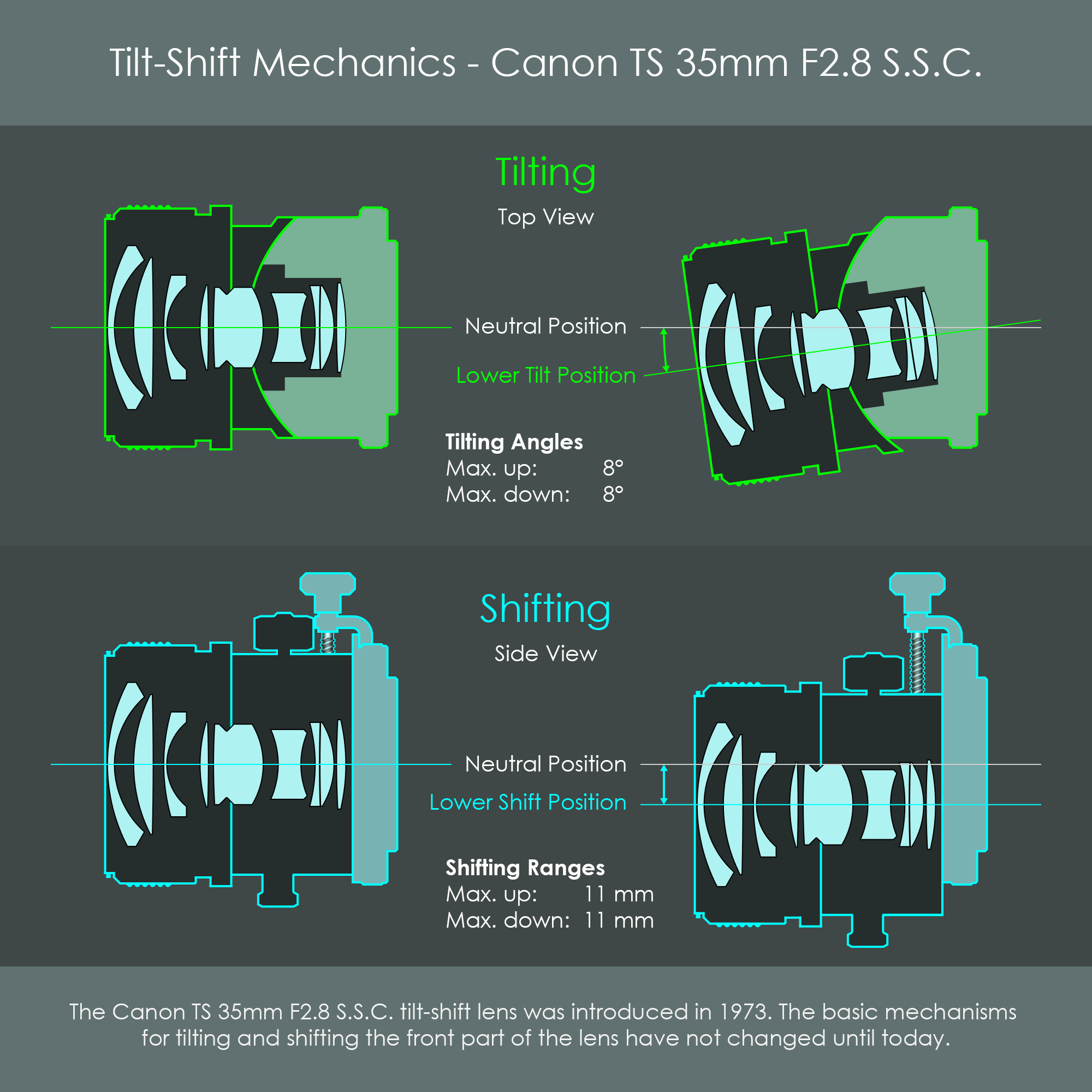
Here is a very short inspection of the Canon TS 35mm F2.8 S.S.C. lens, the great-grandfather of tilt-shift lenses that was introduced in 1973. Prior to this date, photographers had to use foreign lenses that only had one feature implemented, either tilt or shift. The innovative Canon TS 35mm F2.8 S.S.C. was the first lens that offered both tilt and shift function in one product. This made Canon the inventor of the tilt and shift lenses that are known until today. Even though this lens model is long outdated, its core principle is still almost unchanged until today.
The illustration shows how the front part of the tilt-shift lens was moved while tilting or shifting. The tilting mechanism relied on a tilt wheel on the lens barrel that connected to a small gear inside the unit. This gear engaged with a toothed rail on the moving part of the lens. The shifting mechanism used a worm gear that pushed the entire lens up and down when turned via the shift wheel. In either case, all optical elements inside the barrel were moved as an entire unit. This ensured that all imaging characteristics of the lens including optical aberrations remained the same throughout all lens positions.
At the time of the advent of this TS lens, Canon's EF mount system was not yet available for the next 14 years, and therefore this vintage lens didn't have an electronic interface. The aperture was controlled manually via an aperture ring on the lens barrel, and focus was controlled in a similar way, using the manual focusing ring.
With a standard camera setup using a non-tilting lens, the lens plane (which is an imaginary plane perpendicular to the optical axis) is always parallel to the image plane. This in turn forms a plane of sharp focus that is always parallel to the image sensor. If this setup is pointed at a subject that coincides with the plane of sharp focus, this subject gets reproduced as an in-focus image on the camera's image sensor. However, pointing this setup at a subject that is not parallel to the image plane, that subject will be in focus only along a narrow area where it passes through the plane of focus.
Tilting the lens while keeping the image plane unchanged drastically alters the orientation of the plane of sharp focus. Using this principle, a planar subject that is not parallel to the image plane can now be imaged completely in focus from front to back. This can be achieved by tilting the lens slightly towards the subject. A correctly tilted lens even produces a completely focused image of a non-parallel subject with the aperture wide open, a condition that normally creates particularly shallow planes of focus. Therefore, product photographers often use the tilt function to capture a perfectly focused subject and still get appealing bokeh circles from out-of-focus regions. In contrast, the flexibility to adjust the plane of sharp focus can also be used to artificially narrow down the area in which a subject is imaged in focus. If the lens is tilted away from the subject, there is only an extremely narrow portion of the subject in focus. This can be used to simulate miniature effects. As it is impossible with standard lenses to create these ultra-narrow focused areas, the viewer is tricked into thinking that he is looking at macro photography.
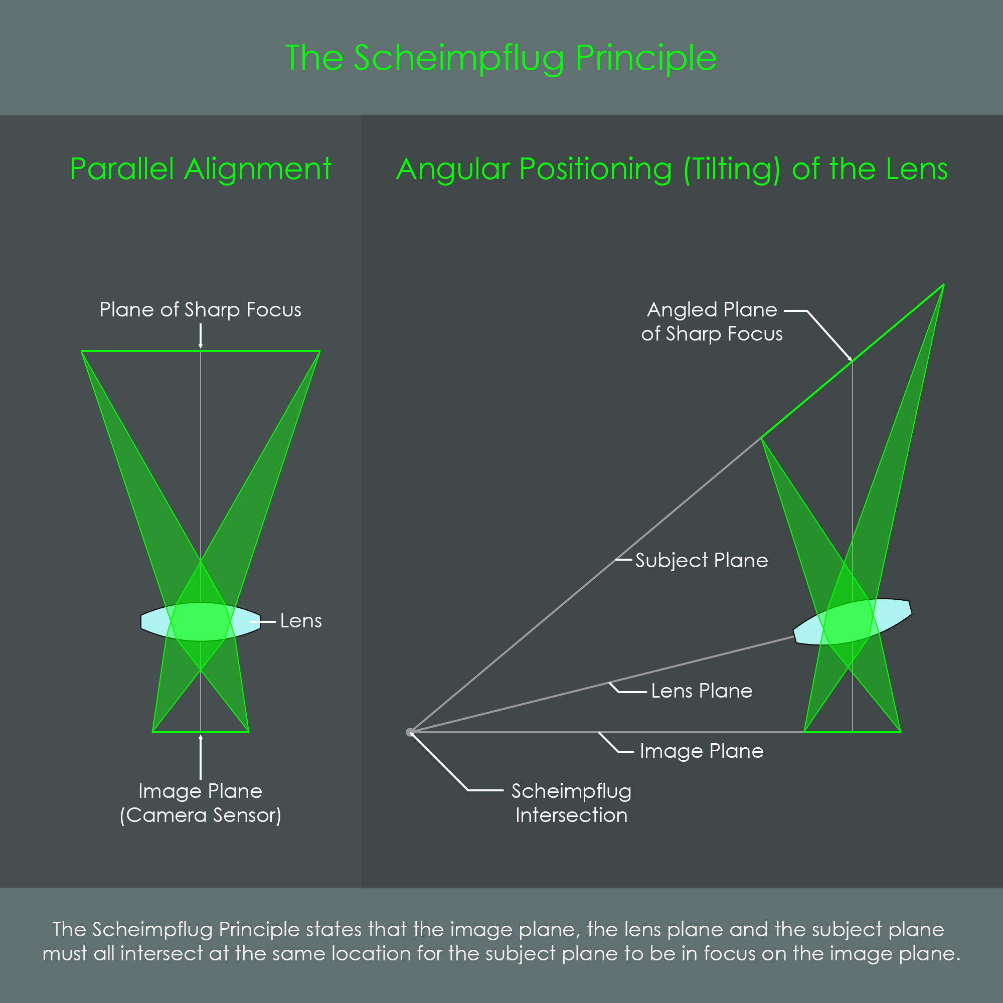
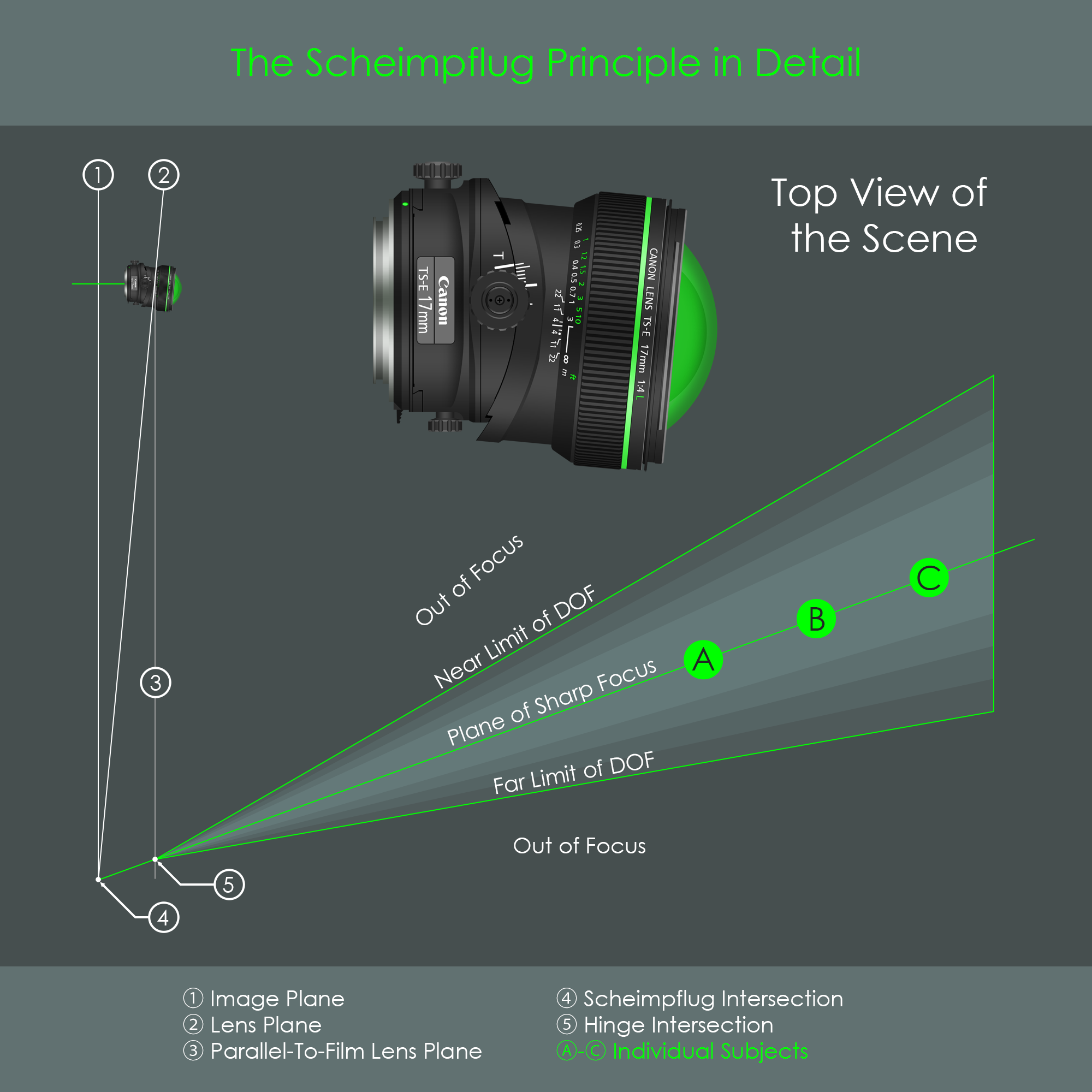
The geometrical relation between image plane, lens plane and resulting plane of sharp focus is described by the Scheimpflug principle. First described by French engineer Jules Carpentier and later documented by Austrian army captain and cartographer Theodor Scheimpflug, this optical rule states the following: All planes – the image plane, lens plane, and plane of sharp focus – always meet at a common location called the Scheimpflug intersection. The illustration clarifies this relation between the planes. Note that the Scheimpflug intersection is actually a line, but as all planes are viewed from the side, this intersection line can only be visualized as a dot in the diagram. The more parallel the planes are to each other, the further the Scheimpflug intersection shifts towards infinity. The illustration summarizes this principle.
Here is a closer look at the plane orientations formed by a tilted lens. It was described that the image plane, lens plane, and plane of sharp focus all meet at the Scheimpflug intersection. If an additional plane is introduced, the parallel-to-film lens plane, another intersection is found – the hinge intersection. This is the intersection where the planes for near limit of depth of field and far limit of depth of field come together. The depth of field (DOF) describes the distance between the closest and farthest positions that can be imaged with acceptably sharp focus. You can read more about depth of field here.
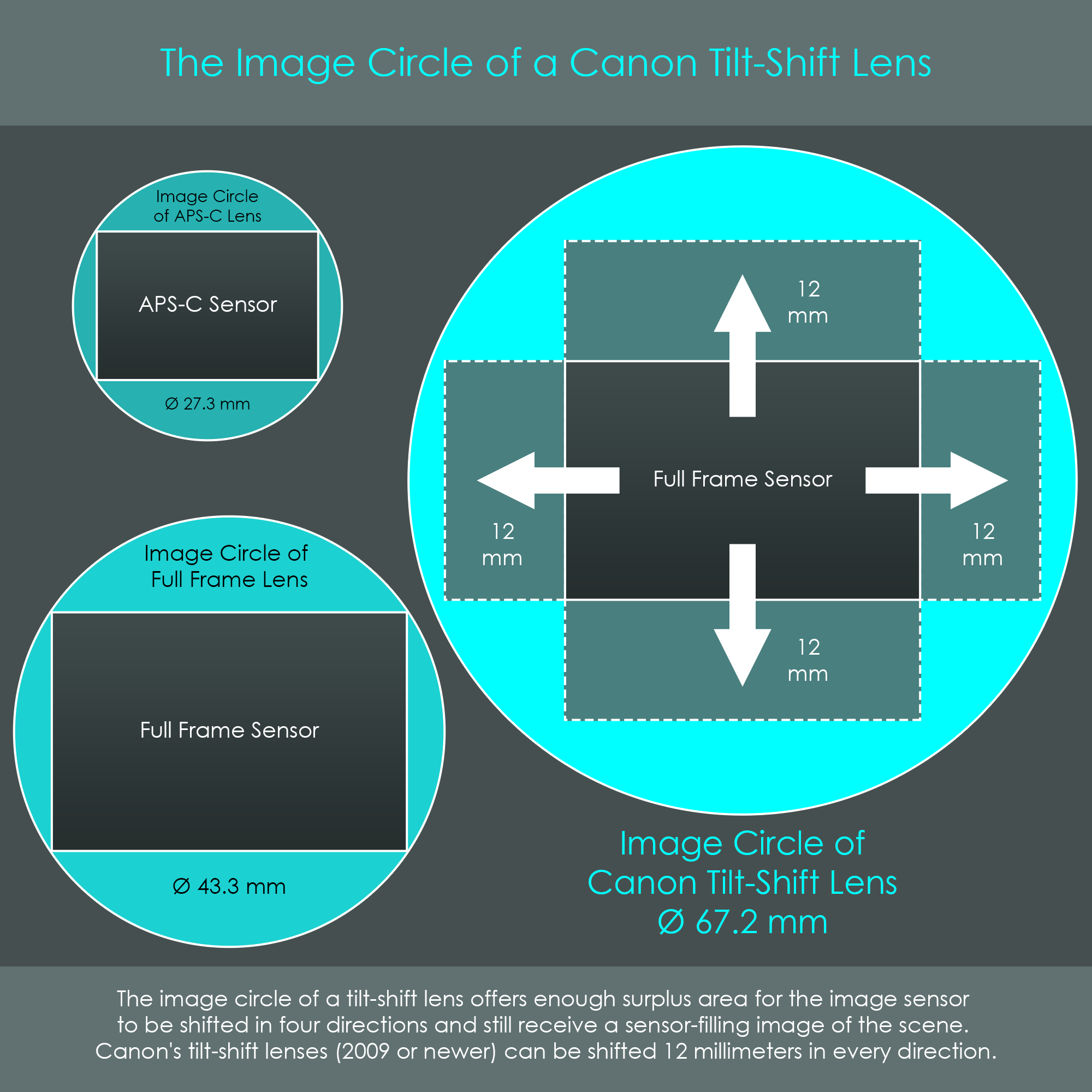
For a non-shifting lens, it is sufficient to form an image circle that covers the camera's image sensor. Canon's EF-S and EF lenses are designed to project image circles with approximately 27.3 mm (EF-S lenses) and 43.4 mm (EF lenses) diameters. These values are equal to the diagonals of the rectangular image sensors.
For the shift function to work, a lens must be specifically designed to form an image circle that is much larger than an image circle formed by a conventional lens. Only then it is possible to shift the lens in any direction and still form an image that is fully covering the sensor.
Canon’s first generation TS lenses (1973 and 1991) project image circles with a diameter of 58.6 mm – this is an overcoverage of around 35% measured by the sensor diagonal. Later TS lenses (released in 2009 and 2017) form an even larger image circle of 67.2 mm – an overcoverage of around 55% measured by the sensor diagonal. These much larger image circles allow the TS lens to be shifted up and down, left or right, and still have a sufficiently large part of the image circle that gets recorded by the image sensor.
In architecture photography, it is important for the aesthetics and realism of the photograph that vertical lines in buildings remain straight in the resulting images. This can be achieved very easily by keeping the camera level with the ground so that the image plane is parallel to the subject. However, if the subject is a tall structure such as a skyscraper, for instance, then keeping the camera level with the ground will very likely cut off the upper part of the tower from the resulting image. A very intuitive solution to this problem is to point the camera upwards so that the entire subject is in the frame. Unfortunately, with this solution the resulting photograph is going to exhibit converging lines. In professional architecture photography, this vertical line convergence is normally an undesired effect, as buildings and other constructions appear to be leaning to the back. The reason for this effect lies in different magnifications: The photographer is typically near the ground not too far away from the skyscraper, and therefore the lower part of the skyscraper gets magnified the most. In contrast, the top of the skyscraper is relatively far away from the lens, and therefore gets magnified to the lowest extent. For that reason, with the camera pointed up, the subject always appears to converge at a central vanishing point. With a standard camera setup using a non-shifting lens, this cannot be solved optically.
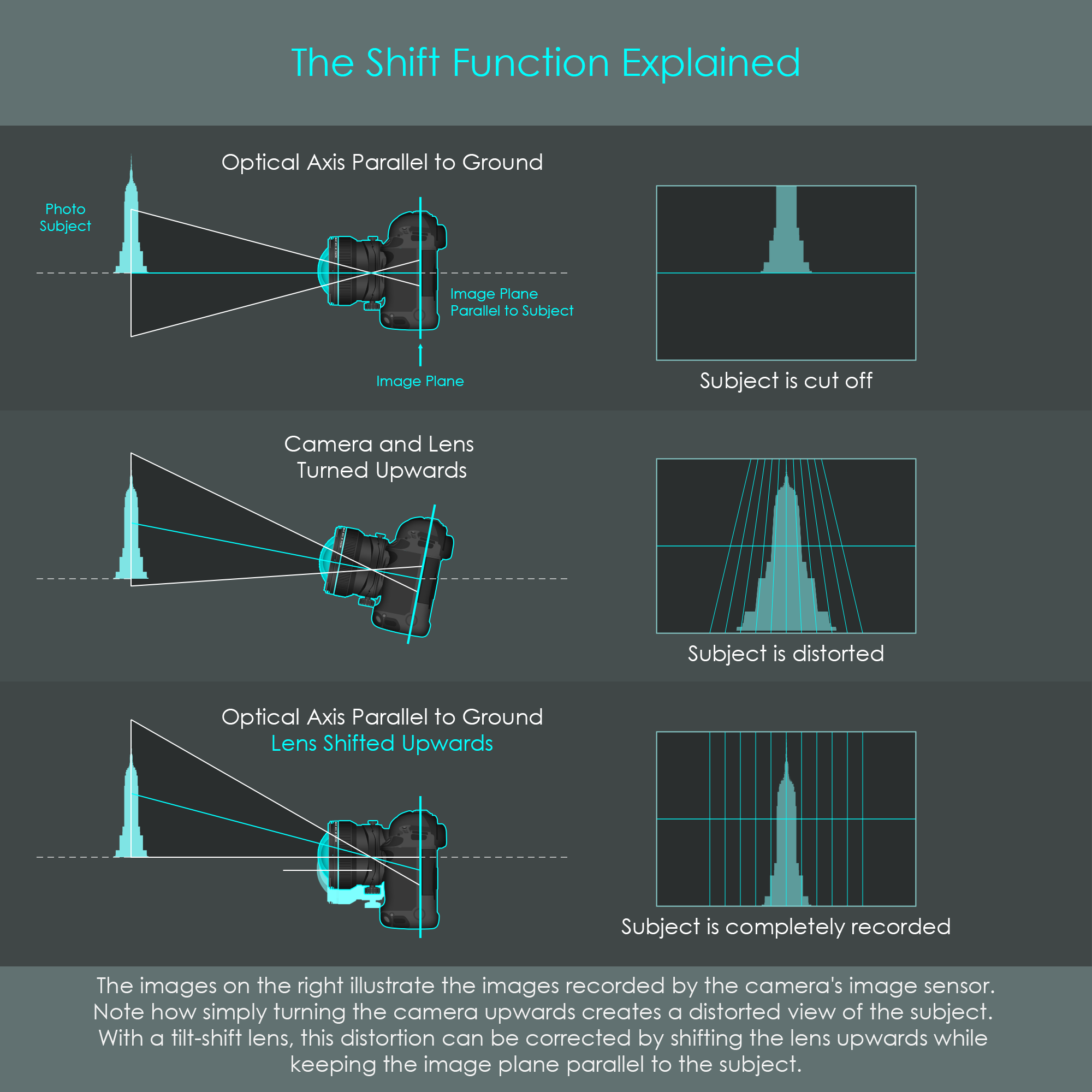
With a shifting lens, vertical line convergence can be avoided. The image plane is kept parallel to the subject at all time. When the lens is shifted upwards, the image circle is also shifted in that direction. This allows a new portion of the image circle to get recorded by the camera, allowing the photographer to frame the shot without changing the camera's angle towards the subject. As a result, vertical lines are kept upright in the photograph, and the entire subject is magnified more evenly across the frame. This is particularly effective when shooting from a low or high angle. When rotating the lens around the optical axis, the shift function can also be used to avoid horizontal line convergence.
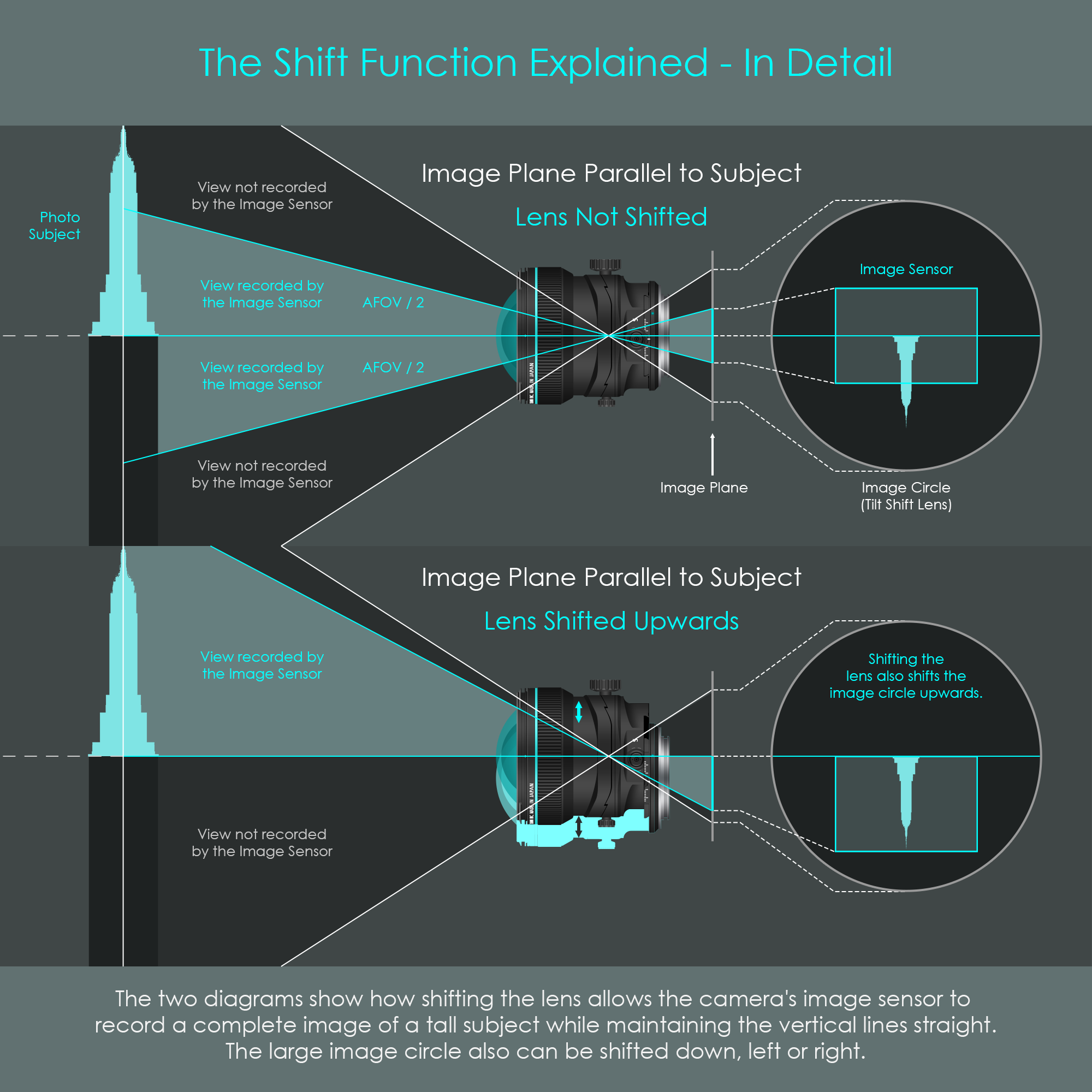
In the zero position of the lens (not shifted), the image sensor records an image from the center of the image circle. With the camera and the lens kept level with the ground, a tall subject is fully imaged by a tilt-shift lens due to the large image circle, but can only partly be recorded by the image sensor.
As soon as the lens is shifted upwards, the image sensor records an image from the lower half of the image circle. This changes the portion of the scene that is photographed. Note how in the shifted position the top of the skyscraper is still farther away from the lens than the floor level. However, the tilt-shift lens produces a rather uniform magnification of the scene due to the fact that the image plane is parallel to the plane of focus. This effectively prevents the vertical line convergence.
Canon's tilt-shift lenses are high-precision optical devices. These lenses deserve the Canon L-designation as they are manufactured to meet highest quality standards. They have particularly small tolerances to ensure that tilt and shift movements are carried out smoothly and precisely. Optically, they are superior to other lenses in two ways: Firstly, they are prime lenses (no zoom range) which are highly optimized to their specific focal length, and therefore they show very little optical aberrations. Secondly, the image sensor is often positioned around the central area of the image circle where imaging performance is usually at the highest level, so there are rarely noticeable aberrations in the corners of an image, especially when in the neutral position.
On the other hand, Canon's TS-E lenses are expensive pieces of equipment. For instance, the Canon TS-E 17mm F4 L tilt-shift lens costs around USD 2.200 (price checked on 11/06/2024). Tilt-shift lenses cannot really be used for a wide range of photographic purposes due to their high degree of specialization, their weight, and the absence of an autofocus system. They are predominantly designed to be used with tripods, which further limits their field of application. Probably the main disadvantage of tilt-shift lenses is that digital post-processing technology increasingly renders the shift function somewhat obsolete. Distorted perspectives introduced by standard lenses can easily be corrected using digital editing software. The tilt function is more difficult to replace, but digital focus-stacking algorithms have made great advances over the past years towards simulating an ultra-large depth of field. It is therefore uncertain to what extent lens manufacturers are going to continue their lines of tilt-shift lenses.
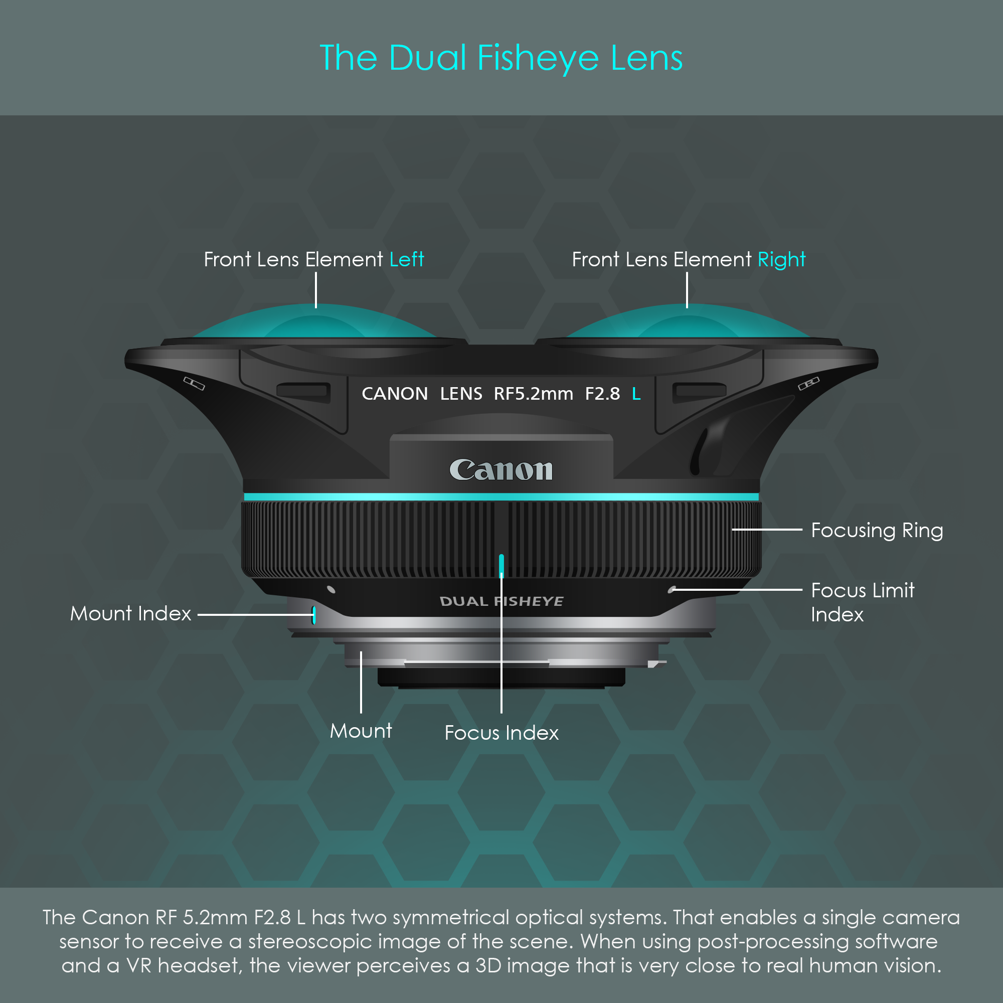
Another highly specialized lens to be presented in this chapter is the dual fisheye lens. Although the symmetrical design of this lens somewhat resembles binoculars, the lens cannot be used as such. This type of lens is designed for stereoscopic photography or videography. Any content recorded via this dual fisheye lens requires a certain degree of post-processing, and can be viewed as three-dimensional images or videos via a virtual reality (VR) headset. The VR headset presents the left image to the left eye and the right image to the right eye. The viewer perceives this as a single three-dimensional space just like in reality.
Stereoscopy has already been explored over 200 years ago, and stereoscopic imaging devices have been designed ever since. Due to moderate acceptance rates of three-dimensional photos and videos, however, only few lens manufacturers have actually produced stereo lenses (including stereo adapters to attach in front of traditional lenses) over the past decades.
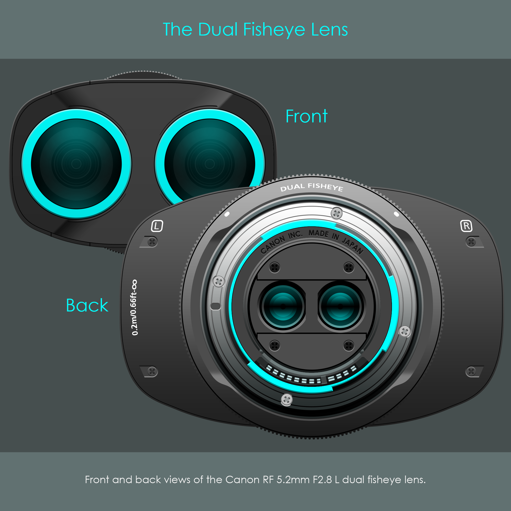
In 2021, Canon has introduced their first stereoscopic lens, the Canon RF 5.2mm F2.8 L dual fisheye. This is a fixed focal length, manual focusing lens with a relatively large aperture. In 2024, Canon added another stereoscopic lens to their line of RF lenses, the Canon RF-S 3.9mm F3.5 STM which includes an autofocus system. The illustration shows both front and back views of Canon's first stereo lens. Note how closely spaced the rear elements are on the back side.
It is apparent that the Canon's dual fisheye lenses are very unique devices. These lenses consist of two identical sets of optical systems with 2x 12 optical elements. The Canon RF 5.2mm F2.8 L is specified to have 12 optical elements in 10 groups, but this specification only refers to one optical path. In reality this lens has 24 optical elements in 20 groups.
Stereoscopic camera lenses try to imitate three-dimensional human vision. On average, the human eyes are 60 to 65 mm apart. It is therefore a requirement that the front lens elements have a similar spacing than the human eyes in order to create a natural feeling of the stereoscopic vision. On Canon's dual fisheye lenses, this spacing (called baseline length) is 60 mm.
With a baseline length of 60 mm, light rays passing through both optical systems must all be recorded by the camera's image sensor. For that reason, both optical paths are brought closer together via glass prisms that redirect the light in a 90 degree angle. The rear lens elements where light emerges from the system are very small and closely spaced in order to fit inside the standard Canon RF mount ring.
Another very unique feature is that Canon's dual fisheye lenses all have two identical electromagnetic diaphragm (EMD) units installed. These are perfectly synchronized with each other, and offer a maximum aperture f-number of 2.8.
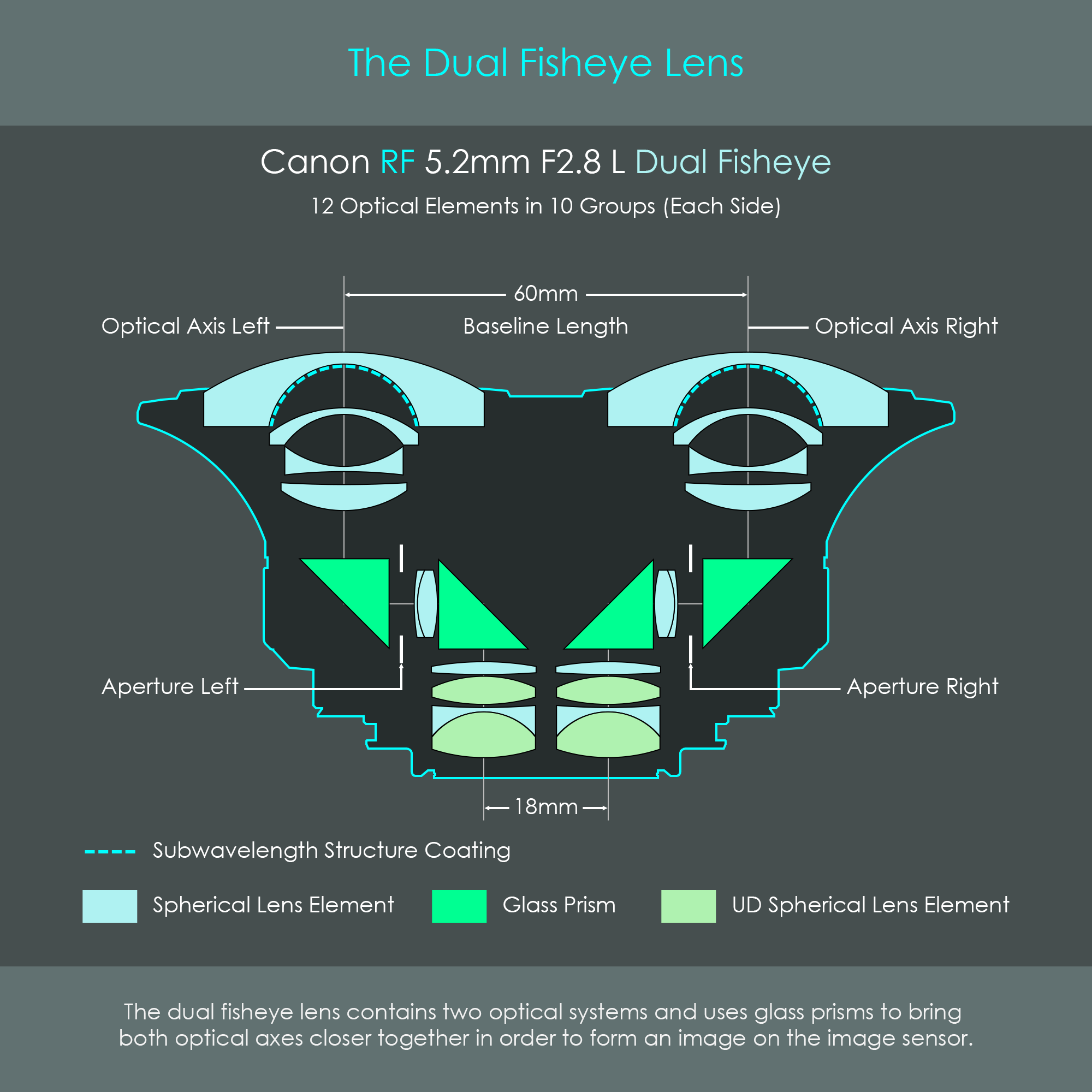
With regards to optical technology, the lens uses ultra-low dispersion glass for two lens elements on each side. Fluorine coating is used on the front lens elements to prevent contaminants from sticking to the lens surface. To keep surface reflections low, Canon uses their subwavelength structure coating (SWC) on some optical surfaces inside the lens.
Optically, the two lenses installed are fisheye lenses with focal lengths of 5.2mm each. Note the retrofocus design of the optics, characterized by the narrow beam of light entering the system and the slightly wider cone of light exiting the lens. Read more about retrofocus design in the chapter about focal length.
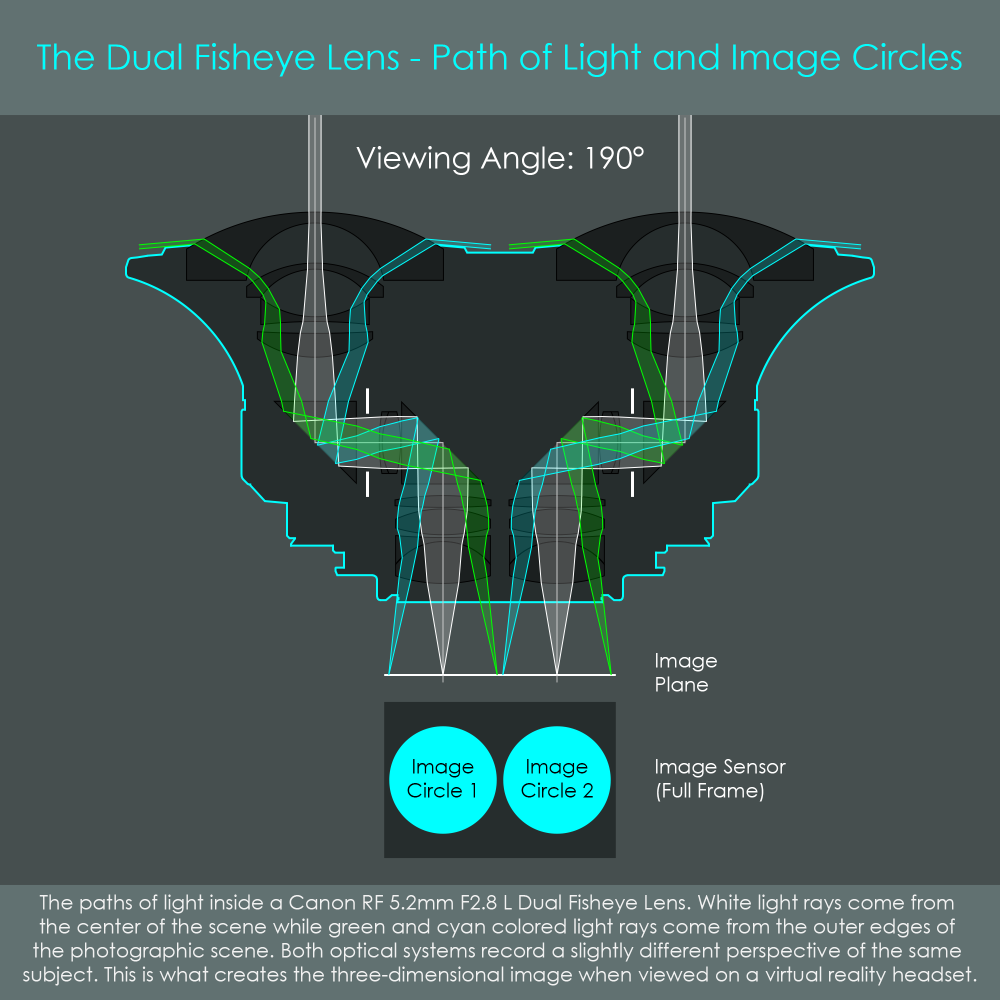
The dual fisheye forms two image circles on the image sensor. The fact that both image circles are recorded by the same image sensor ensures that the pair of images has identical focus, exposure, and white balance settings. This is an important requirement for stereoscopic images to be immersive and realistic.
When used on a Canon R5 mirrorless camera, for example, the image circles of the dual fisheye are recorded by the full frame image sensor with a resolution of 35 megapixels (8.192 x 4.320). Each image circle is roughly 4.000 pixels in diameter, resulting in roughly 12 megapixels each.
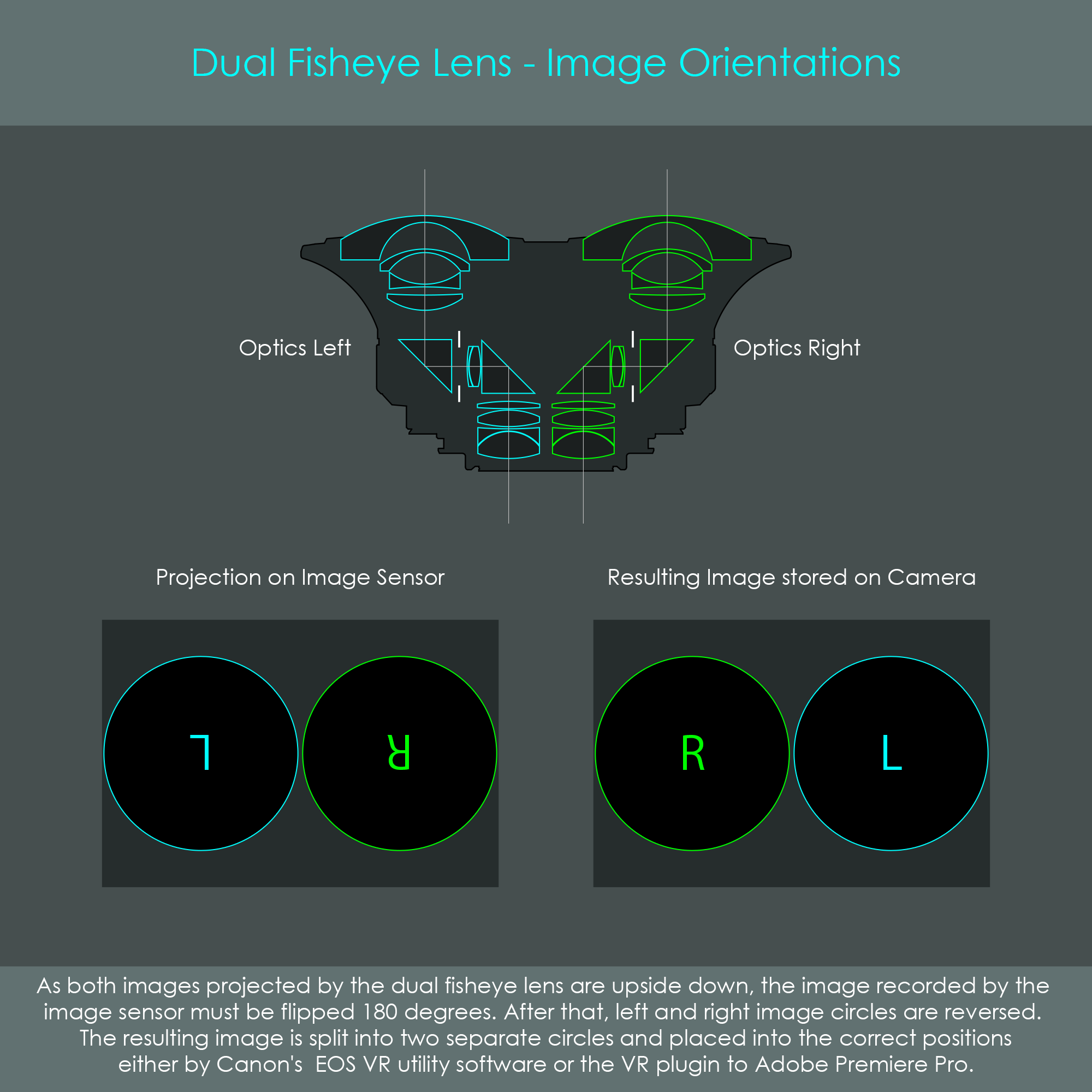
For a stereoscopic image to be viewed, a virtual reality headset is required. The headset is designed so that the left eye can only see the left image and the right eye can only see the right image. For the images to be correctly displayed in the VR headset, the image recorded by the camera must undergo certain steps of post-processing.
One of these post-processing steps involves the splitting and repositioning of the image circles. As the illustration shows, the two image circles are initially in the correct positions but upside down. The resulting image (when viewed on the computer screen) is upright, but has left and right positions swapped. The post-processing software cuts the resulting image file in half, and displays each image circle to the correct eye position accordingly.