The history of autofocus systems dates back to the 1970s where numerous concepts have been developed. This chapter focuses on some of the more relevant and more recent designs of autofocus systems.
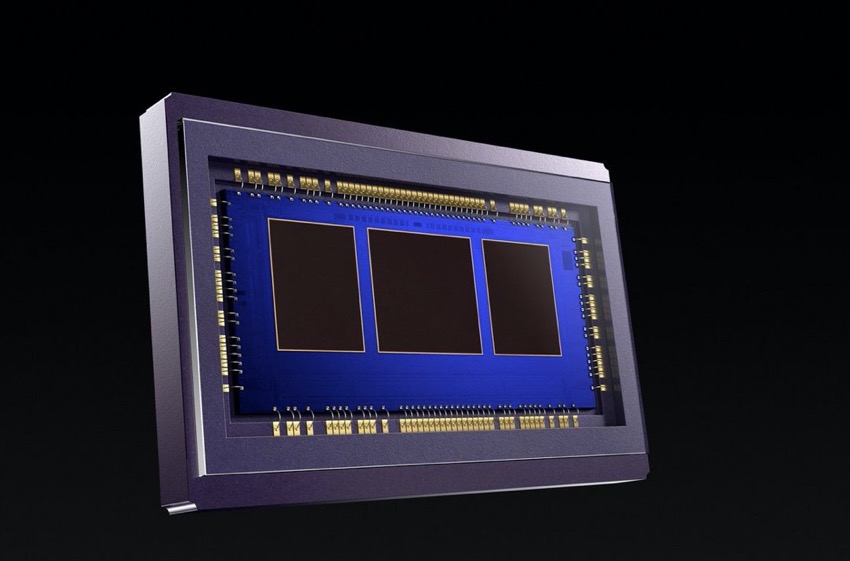
The image shows a phase detection autofocus sensor of a Canon EOS-1D X Mark III DSLR camera. Released in 2020, that camera has one of the fastest autofocus systems currently available to photographers.
In January 1985, the Minolta Maxxum 7000 was introduced with the first autofocus detection module that was integrated behind the photo-taking lens. Due to its layout, this type of measurement is called through-the-lens (TTL). Also, TTL phase detection is based on a principle where a secondary image is registered by a special sensor unit, which is why it is also referred to as through-the-lens secondary image registration phase detection autofocus. TTL phase detection still plays a significant role in digital SLR photography today and therefore this article places a clear emphasis on this passive autofocus system.
Phase detection (PD) is a technique where the primary image (the one that is formed by the main photographic lens and that is recorded by the image sensor during the photograph) is evaluated by a specialized autofocus sensor unit. That autofocus sensor is located in the lower area of the camera body. The camera has a secondary mirror that reflects incoming light towards the autofocus sensor. That second mirror is placed directly behind the primary mirror and it receives approximately half of the incoming light due to the fact that the primary mirror is semi-transparent. With this configuration, the autofocus sensor can analyze the image that the photo-taking lens produces. For that reason, TTL phase detection is considered to be extremely accurate as its calculations are based on the same optical system that forms the final image on the sensor. Regardless of the actual positions of the parts, in the interest of clarity, some of the following illustrations show a linear arrangement of the phase detection system, not showing the primary and secondary mirrors.
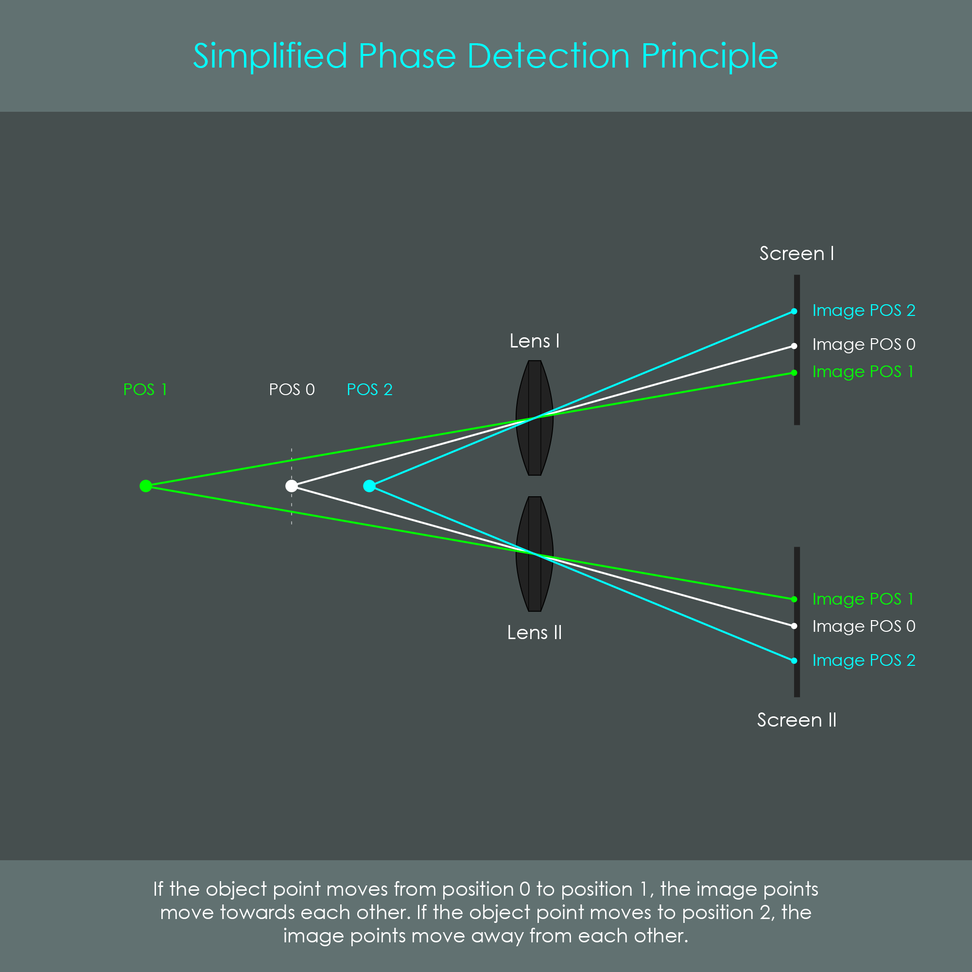
The principle is to install two optical systems that produce two individual images of the same object but from different perspectives. Once the object changes its distance from the optical system, the two images also change their position. An increasing distance between the object and the optical system results in the two images shifting towards each other. If the object is approaching, the two images move away from each other. For the analysis of both image positions, two screens are placed so that they can detect every possible situation. The diagram shows this concept.
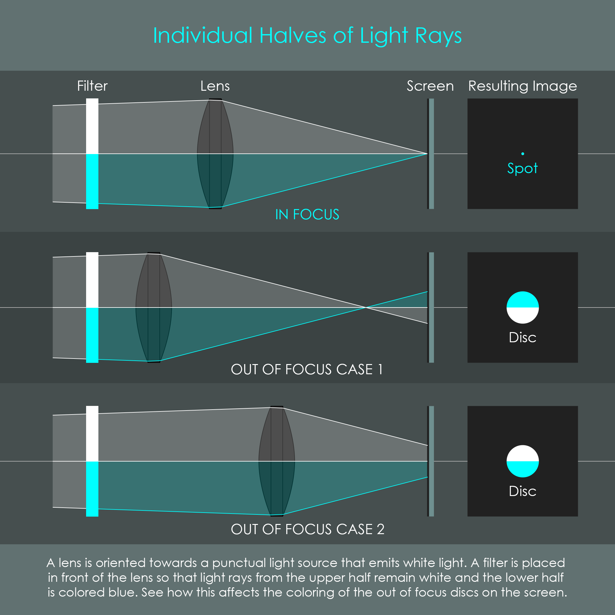
Although there is only one photo-taking lens in a camera, TTL phase detection still requires to record two images from two different perspectives. Interestingly, this can be achieved by dividing light rays that pass through the photo-taking lens into two halves. This concept can be visualized easily by showing a lens that projects the image of a point-like source onto a screen. A color filter is placed in front of the lens so that the lower half of light rays is colored differently than the upper half. The separate colors help to distinguish the rays that pass through each half of the lens and to draw conclusions from the final image to the origin of the light ray. The diagram summarizes this idea. If the point source is in focus, the image is also formed as a point. If the point source is out of focus, the image is formed as a disc where the arrangement of colors indicates the direction in which proper focus can be achieved.
Phase detection adopts this principle and uses the light coming through opposite halves of the photo-taking lens. Each optical system receives light only from its half of the camera lens and forms a secondary image on individual, one-dimensional CCD sensors. When the subject is in focus, two secondary images are formed on the »in-focus-spots« of the linear detectors. These in-focus-spots are not exact positions on the CCD sensors but the camera's control system has the exact distance stored at which identical signals from both CCDs have to be apart in a correctly focused situation. This predefined distance serves as a reference for the focus condition. The system detects an out-of-focus situation when the secondary images on their respective CCD sensors change their distance towards each other by shifting towards or away from each other. The figure shows this basic principle, assuming that the camera is looking at a single bright spot on a black background, producing two sharp peaks on each of the CCD sensors.

The distance between the secondary images also indicates the direction in which the camera lens has to be moved in order to achieve proper focus. It should be noted that the two images not only change their relative position, but also will become blurrier the further they leave their in-focus-spot. Fortunately, as the blur occurs identically on both CCD sensors, the CPU is usually still able to calculate the required focus adjustment. Still, blur can be problematic for certain low-contrast scenes and other situations. The secondary image formation lenses, also referred to as separator lenses, are located behind little masks that are designed to prevent stray light from reaching the CCD sensors. These masks also limit the portions of light so that not an entire half of the photo-taking lens is used for the secondary image formation but only two bundles of light forming two »windows« in the photo-taking lens. Each separator lens can therefore »see« through its own dedicated window.
In reality, photographic scenes do not only consist of point-like sources but rather of widespread objects including a large number of points. For that reason, a real phase detection analysis must be capable of analyzing widespread objects including both on-axis points and off-axis points. In this case, the CCD sensors do not register single peaks but rather a specific waveform. The waveform CCD I produces is identical to the one produced by CCD II, however they may be phase-shifted, hence the name phase detection or phase comparison. The signals registered by the CCDs can also be compared to signatures that must be brought to coincidence in a reference position. Unfortunately, a phase detection unit as depicted above would only be able to calculate the phase difference for a pinpoint object located on the optical axis or very close to it. With objects off the optical axis, a phase detection unit of this simplified type would lose its function. The bundle of light from an off-axis object is running in a different direction, not covering both separator lenses symmetrically, and therefore causing the intensity on one CCD sensor to decrease or even drop to zero. The diagram below shows both cases.

It can be seen that there is an asymmetry between both windows that is increasing with the distance of the object from the optical axis. In case 1, the top window is already narrowed by the top of the lens, causing the intensity of the signal registered by the lower CCD to be lower than the signal of the upper CCD. In case 2, the asymmetry is so strong that the lower separator lens is entirely cut off from light.
The solution to this problem is to install a condenser lens (also called field lens) that conjugates each separator lens with its specific window in the photo-taking lens. To put it simply, the condenser lens 'bends' the cones of light from off-axis objects so that they always illuminate both separator lenses. In addition, the implementation of a condenser lens increases the flexibility in the choice of the focal lenghts of the separator lenses. Another mask is placed in front of the condenser lens to block those portions of light that are not used for the phase comparison. The illustration clarifies this key role of the condenser lens.
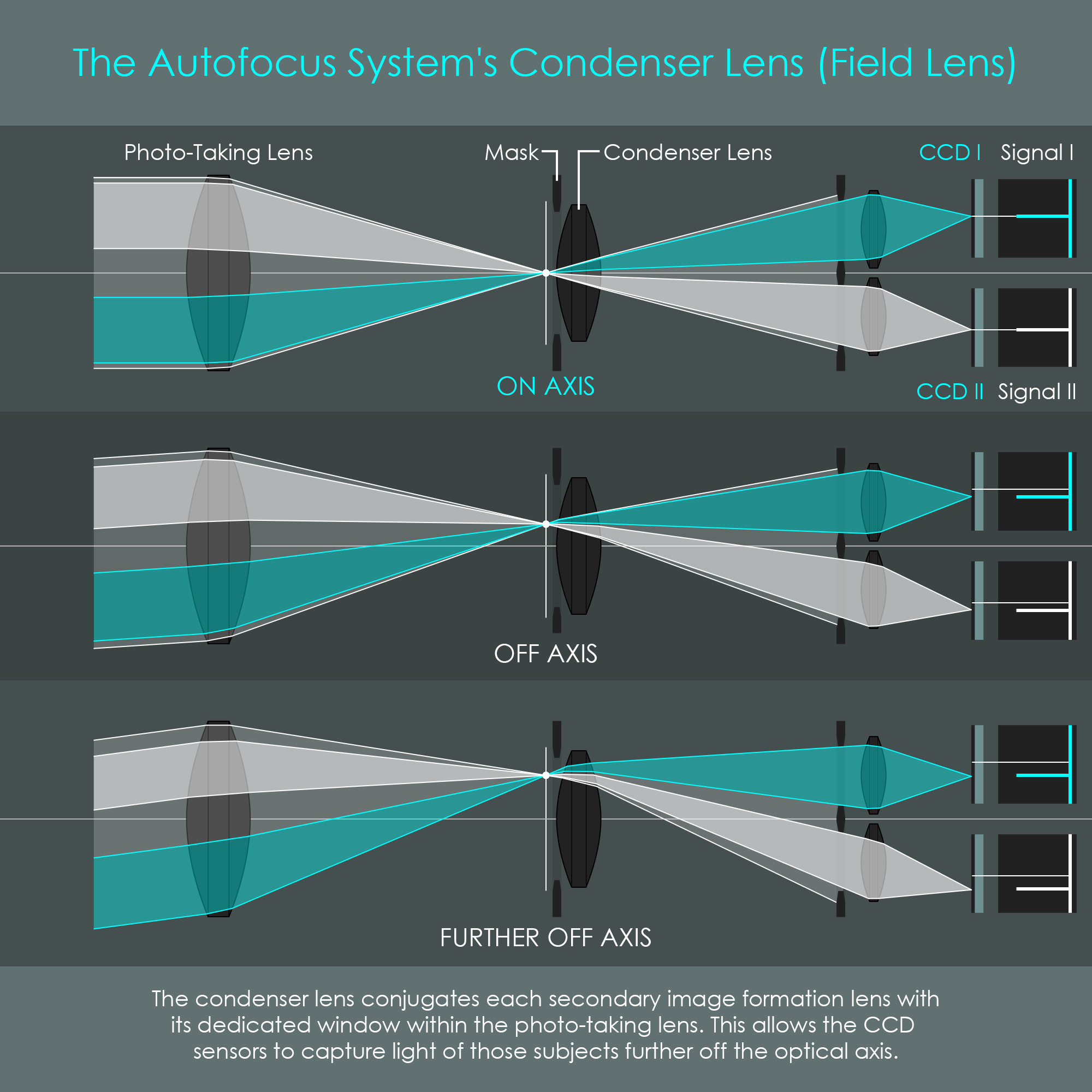
For primary image points off the optical axis, both secondary images registered on the CCD sensors are shifted in the opposite direction. Once the phase detection system registers two identical signatures on the CCD sensors that are shifted in the same direction (other than the opposed out-of-focus-shifts described earlier) it still associates these signatures with an in-focus-situation. This is because both signatures have the same distance from each other. Therefore, the general principle of phase detection also applies for off-axis subjects. On closer inspection, the illustration reveals that there is still a small asymmetry between both windows, even with a condenser lens installed. However, this slight asymmetry isn’t problematic as both separator lenses are fully illuminated. In general, the size of the windows in the photo-taking lens is only limited by the separator masks and the lens aperture while their position depends on the position of the primary image point.
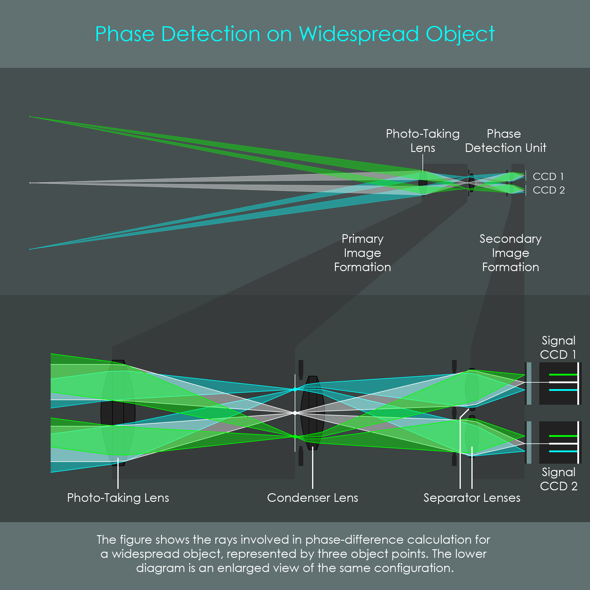
The illustration is a combined view of the image formation process while looking at a widespread scene, including a central object point (white) and two off-axis points (green and cyan). The figure only includes those rays relevant for phase detection and not those blocked by the separator masks. For that reason it should be noted that the actual photo is taken with the full beam of light covering the entire lens surface, limited only by the size of the lens aperture.
It can be observed in the enlarged view that the condenser lens refracts the outside rays into the required direction. For that reason the condenser lens allows the autofocus unit to analyze widespread scenes. It also ensures a constant signal intensity along the active area of the CCD sensors. Finally, it slightly reduces the angle in which light rays hit the CCD sensors, and therefore it reduces blurring for the out-of-focus situations.
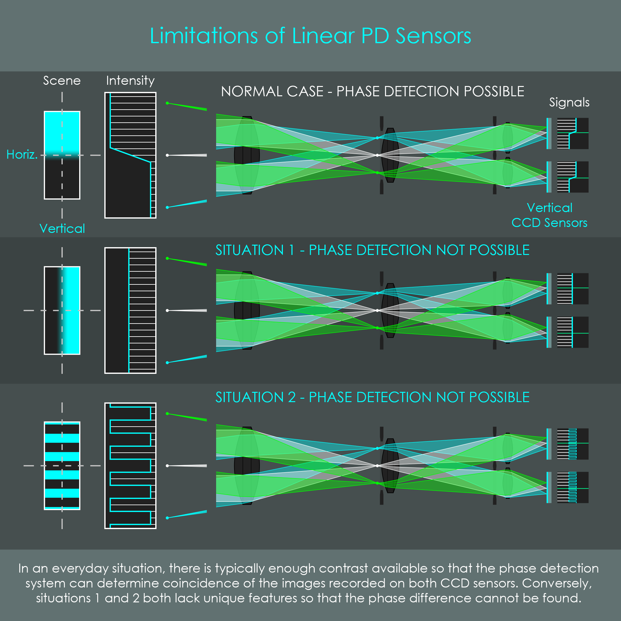
Depending on the scene to be photographed, TTL phase detection autofocus suffers from a general weakness. Firstly, phase detection can only be applied when the scene’s brightness is above a certain minimum level. Furthermore, one pair of linear CCD sensors arranged vertically is only sensitive to horizontal contrast edges and vice versa. If a subject contains a contrast edge that is oriented in the same direction as the pair of CCD sensors, the signals recorded do not include unique features and the comparator is unable to bring the secondary images to coincidence. Consequently, it is also impossible to determine focus if no contrast edge is available at all, like in a clear blue sky. It is almost equally impossible for a phase detection system to focus on highly repetitive surfaces such as fine checkerboard patterns. The illustration visualizes two very typical limitations of linear phase detection sensors.

In order to avoid focus inabilities as indicated in situations 1 and 2, most focus points combine two pairs of linear CCD strips arranged in a right angle (cross-type AF points). The installation of cross-type AF points in turn requires four separator lenses with individual masks and therefore is not an option of all AF points due to space limitations. It is typically the AF points in the central area of the scene that have a cross-type design whereas the outer AF points have a linear design. With these cross-type autofocus points, a vertical contrast edge can be easily registered by the horizontal pair of CCD strips. Consequently, a cross-type autofocus point is comparing four secondary images being formed by four bundles of light within the photo-taking lens. The diagram compares both AF point types with their associated separator lenses from a top view.
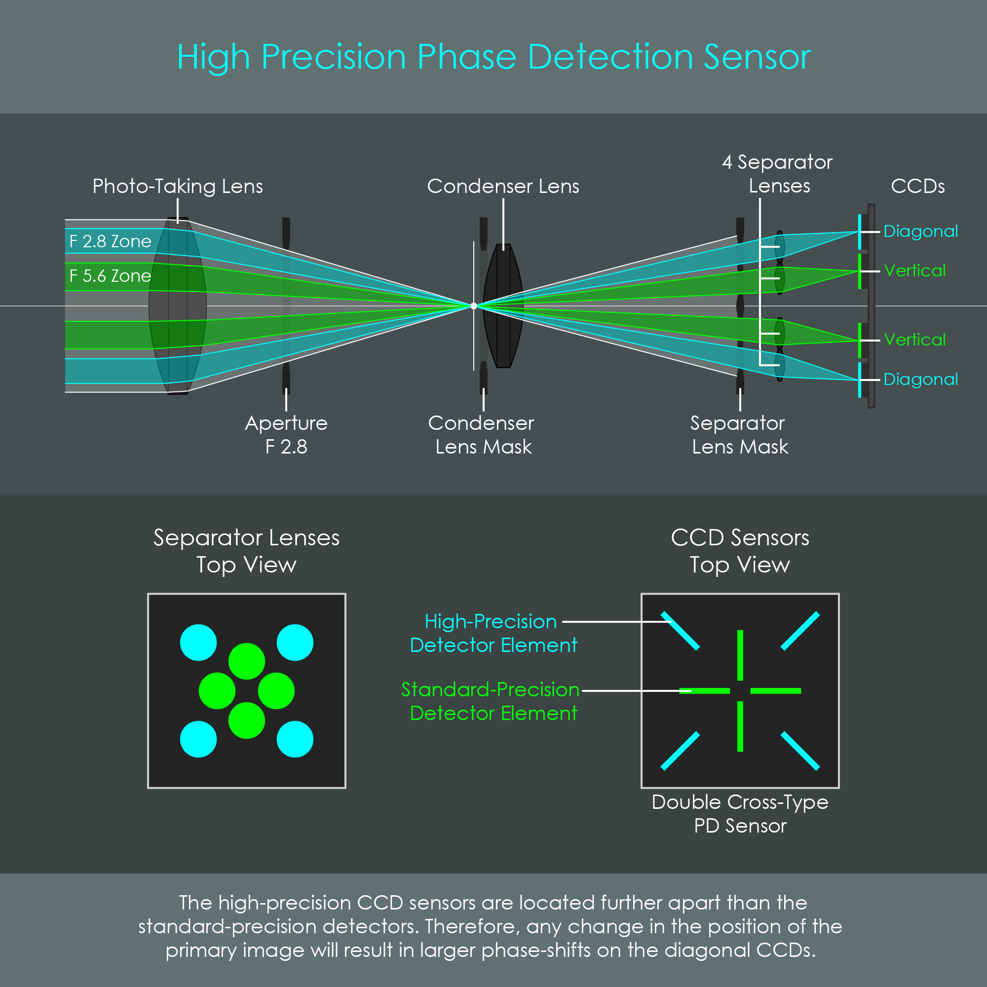
One important aspect of phase detection is that the accuracy of focus detection is related with the distance between the light rays analyzed. It was shown in the illustrations above that the phase detection unit analyzes light coming through opposite halves of the photo-taking lens. In fact, these zones are much smaller than half of the lens due to the separator masks. If the phase detection analysis was made on light zones lying too close together, the phase shifts on the CCDs would be too small, reducing accuracy too far. Instead, the distance between the opposite zones should be as large as possible to achieve noticeable phase shifts on the CCDs. The system can be compared to a rangefinder where each pair of CCD detectors forms a baseline for triangulation and the accuracy is increased as the distance between both CCDs is increased. On the other hand, it is required for the lenses to provide apertures that accommodate these zones. Unfortunately, not all photographic lenses have a maximum aperture larger than f5.6 which is why phase detection units typically are designed so that most of the AF points analyze light rays from two or four bundles of light within the f5.6 zone.
To allow for some higher accuracy measurements, some professional DSLR cameras provide high-precision AF points that can analyze bundles of light within the f2.8 zone. Naturally, these high-precision AF points only become available when the photo-taking lens provides a maximum aperture of f2.8. Without such as fast lens, the AF point only relies on the standard detectors. The linear CCD detectors for these high-precision AF points must be further apart than the standard detectors and are typically arranged vertically in relation to the other detectors. Also, an additional set of separator lenses and masks is required. For a certain shift in the primary image, the phase-shift registered by these high-precision detectors is larger than the one registered by the standard-precision ones. Therefore, the comparator unit can recognize the tiniest focus shifts even when the standard detectors already indicate proper focus. The combination of four standard-precision detectors and four high-precision detectors creates a double-cross-type AF point. The diagram summarizes the concept of high-precision autofocus points.
It should be noted that it does not influence the autofocus ability if the aperture of a lens is set to a high f-number. For example, with an f2.8 lens applied, the photographer can choose an aperture of 16 or 22 on the f-number preselection and the phase detection unit is still able to use its high-precision autofocus points. This is because the aperture is always fully open when the mirror is in its idle position. The aperture blades only snap into the desired position when the shutter is pressed.
Although offering higher focusing precision, the high-precision AF points do not enhance focus accuracy in dark environments even if an f2.8 lens is used. An f2.8 lens inevitably is more suitable to record images in darker environments, but the phase detection unit always picks the same bundles of light for phase comparison. Rays of light from the f2.8 zone are projected onto a separate couple of CCD sensors, and therefore do not contribute to the intensity on the standard set of CCD sensors. The high-precision CCDs will either receive some light or no light at all, depending on whether the lens has a maximum aperture of f2.8 or smaller. Thus, the standard CCD sensors always receive the same amount of light regardless of the available lens aperture.

Another improvement to the accuracy of a phase detection autofocus sensor is achieved by a dual-line zig-zag arrangement of line detectors. The width of a single pixel on a standard-precision CCD strip is rougly between 10 and 14 µm. For certain AF points – usually the most commonly used ones in the central portion of the screen – the AF sensor has the vertical CCD strips replaced by four parallel detectors, two of which directly adjacent to each other. In addition, these two parallel detectors are shifted by half a pixel which effectively doubles the resolution of such an array. With the zig-zag design, the secondary image coincidence can be determined more accurately because unique signal features that would potentially fall between two pixels in a regular detector array will fall on a pixel of the additional array. The diagram shows the sensor layout of the Canon EOS 7D with the central vertical zig-zag pattern clearly visible.
To increase flexibility for focusing on various objects, DSLR cameras usually allow the selection of different AF points. One pair of CCD strips can actually represent more than one AF point by switching the in-focus-spots that serve as the reference for phase comparison. Assuming that two CCD strips have their in-focus-spots exactly in the middle, the camera’s CPU can shift these reference lines in the same direction and define this position as the new in-focus-spot. In contrast, if an AF point should be moved perpendicularly to the CCD strips, additional line sensors have to be installed next to the existing ones. This means that for three vertical cross-type AF points it is only required to have one pair of slightly longer vertical CCD strips [|] and three pairs of horizontal CCD strips that are placed above each other [≡]. If two more pairs of vertical strips would be added, this arrangement could even represent nine cross-type AF points.
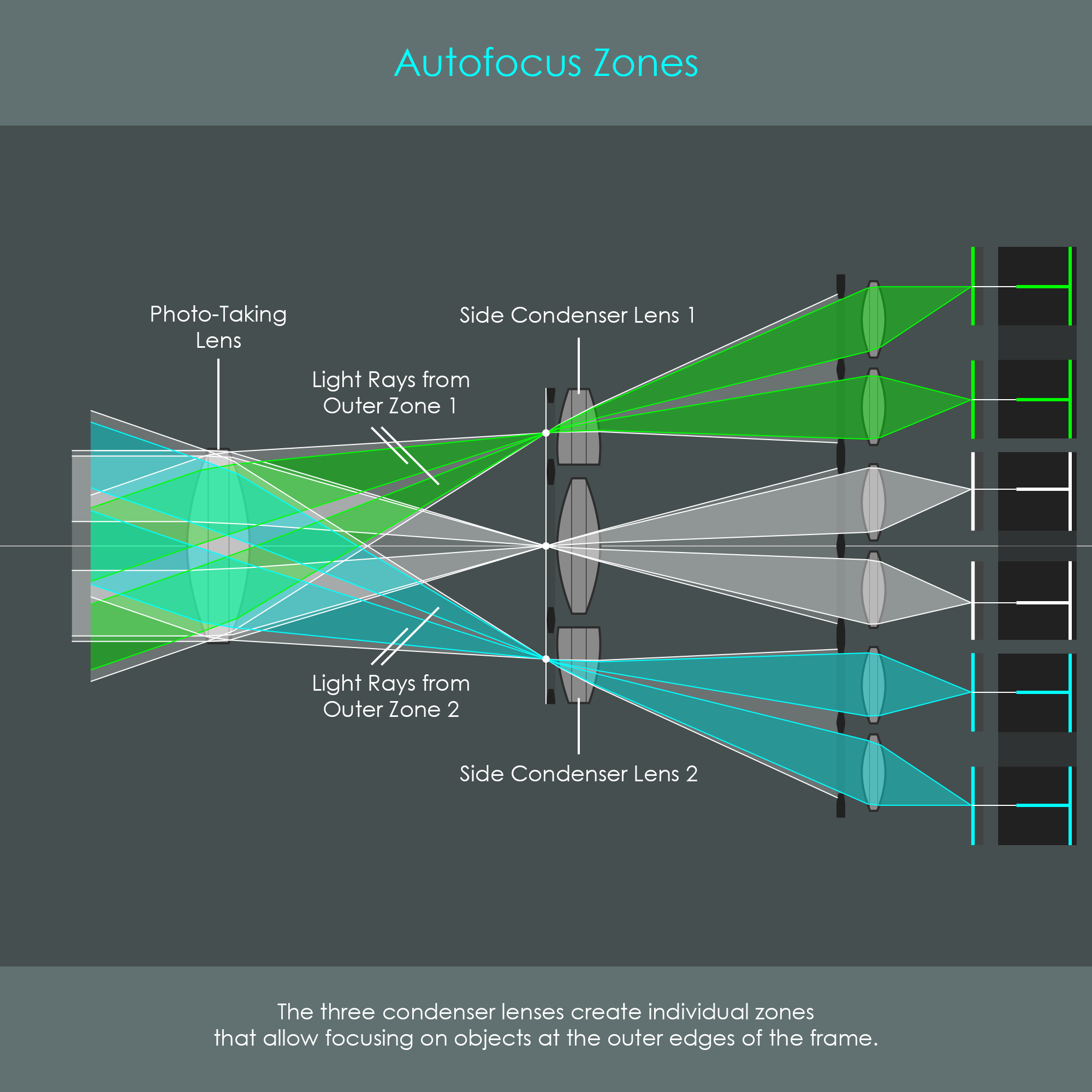
This principle requires the combinable CCD strips to be placed behind one set of separator lenses. A phase detection unit that is pointed towards the center of the image can indeed capture a fairly decent portion of the scene including the off-axis light rays that have been discussed earlier. Unfortunately, object points from the side regions of the image can only be analyzed by additional installations. Thanks to the use of condenser lenses, additional phase detection units can be placed to the outer zones of the image area. Depending on the required number of separate zones, a certain number of condenser lenses is placed in the primary image formation plane. Subsequently, new groups of separator lenses and CCD strips need to be arranged behind those condenser lenses. Today’s cameras typically have three AF zones for which three condenser lenses are installed. The following diagram shows the concept of creating multiple AF zones.

The illustration compares the technical design of an AF sensor with the resulting array of autofocus points. It can be helpful to note that the effective area used for the phase detection analysis is actually larger than the single AF points as they are displayed in the viewfinder. The effective area for phase comparison is determined by the image area that linear or cross-type detectors actually cover. The AF point itself is only a visualization to display in the viewfinder.
It can be seen in the illustration of the sensor layout above that most of the AF points are standard-precision cross-type points (thick white squares). In the Canon EOS 1D X (introduced in 2012), only five inner AF points are high-precision double-cross-type points (thick cyan colored squares). The remaining points (thin white squares) are linear vertical detectors. It can clearly be seen that not every individual AF point has its own pair (or two pairs) of line detectors. Each pair of long vertical detectors in the central area is used to cover seven AF points vertically arranged. Each pair of horizontal detectors of the central area covers three AF points horizontally arranged. For this reason, these 28 pairs of (vertical and horizontal) detectors cover a total of 61 AF points. The 20 diagonal detectors do not form own AF points but enhance the precision of the inner five AF points.
For reasons of simplification, it was assumed in the illustrations above that the autofocus sensor was positioned in one line with the main photographic lens. In reality, however, light rays coming from the photo-taking lens are deflected towards the lower area of the camera body by the secondary mirror – the one behind the semi-transparent primary mirror. With this setup, the primary image is formed at the geometrical equivalent of the sensor plane. The deflection of the incident light does not change the principles of operation described above. The diagram shows a cross-section of a phase detection autofocus unit as applied in the Canon EOS 5D Mark II and gives an idea of the proportions in a phase detection unit.


Last but not least, what looks rather simple on two-dimensional illustrations is truly a high precision optical device capable of detecting phase shifts in the micrometer range. The diagram on phase detection unit parts is a three-dimensional representation of all the individual components that interact so perfectly.
It is a number of advantages that have made phase detection the most common type of autofocus system in today's DSLR cameras. The autofocus unit itself does not require any moving parts and is therefore not vulnerable to vibrations. Also, the position of the AF unit behind the photo-taking lens offers very high accuracy as the primary image is analyzed directly. Possibly the greatest advantage of phase detection autofocus is its high speed. Once the comparator has determined the phase-difference, the system already knows to which position the camera lens has to be moved. Unfortunately, the disadvantages are its low usability in dark environments and for scenes with low contrast or highly repetitive fine patterns. Also, phase detection can only be applied as long as the camera’s mirror is in its idle position. In live-view mode where the mirror is flipped up, another technique must be applied to determine proper focus. Finally, higher production cost is a slight drawback for phase detection systems. With the growing popularity of mirrorless cameras and their innovative autofocus systems, phase detection is slowly getting pushed out of the market.
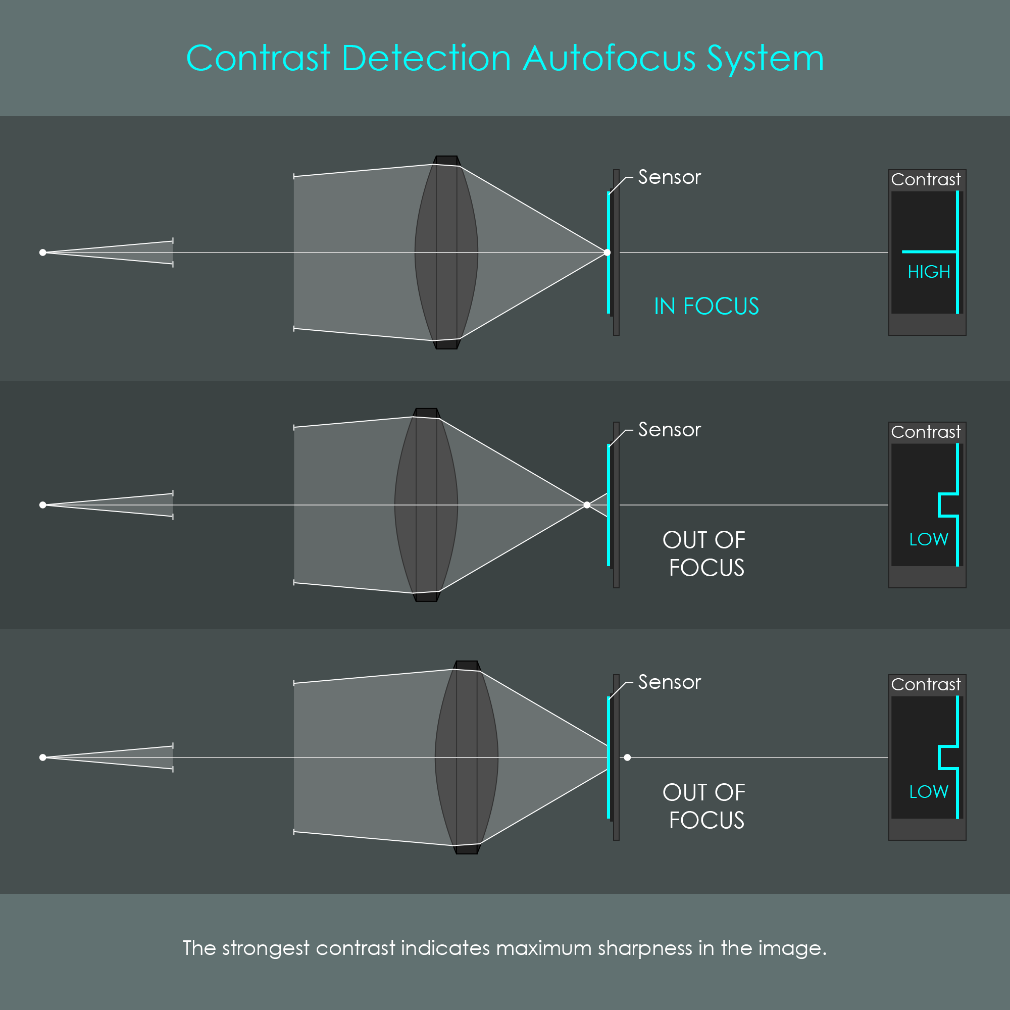
With the introduction of the first mirrorless digital cameras in the late 1990’s, a new autofocus technology had to be developed. With no reflex mirror, incident light from the photo-taking lens could not be redirected towards a dedicated autofocus sensor. Mirrorless camera manufacturers have therefore developed an autofocus method called contrast detection. The camera uses the main image sensor for autofocus detection, and the camera's CPU performs a continuous reading of the scene during focusing. Perfect focus usually coincides with maximum contrast on the image sensor and therefore, this type of autofocus measures the intensity of contrast data within a selected focusing region. The illustration below shows the relation between focus and contrast.
Contrast detection is also used for cameras in notebooks, smartphones and tablets where space is very limited. On DSLR cameras, contrast detection autofocus is usually activated when the reflex mirror is folded in the upper position, which is usually during live-view mode or when shooting video.
Here is a step-by-step description of this iterative procedure for the determination of focus with the contrast detection technology: In a first step, the focus detector circuitry receives a snapshot of the contrast situation provided by the image sensor. However, there is the problem that no information is available about whether the current snapshot already represents the strongest contrast or if the current focus situation can be optimized. Also, if low contrast is detected right at the first snapshot, the system doesn’t allow conclusions on whether the low contrast results from the focal point being in front or behind the image sensor and therefore, no direction can be identified at this step.
For these reasons, the focused position is usually detected by a gradient method – called the »hill climbing method« – in which a peak in a curved line of contrast values is searched. In the second step, the focusing lens is driven in a predefined direction while successively taking snapshots of the contrast situation in order to determine the orientation of the gradient. If the contrast decreases, the system changes the direction of the lens movement immediately. As long as the contrast increases, the lens keeps moving until the contrast data has a peak value. To confirm whether the contrast data is actually at its peak, the focusing lens is driven so as to surpass the focused position, detecting lower contrast again. Consequently as a last step, the focusing lens is driven back to the position that has produced the peak signal. The diagram visualizes the hill climbing method.

It is necessary to limit the active focusing region so that not the entire image sensor is evaluated but only pre-selected focusing zones. A reason for the use of smaller focusing zones is that a scene very often includes areas that deliberately should remain unfocused, such as undesired background or other elements that might distract the viewer from the actual subject. If the contrast detection autofocus system reads the entire image sensor for focus detection, any large-scale areas would be prioritized, leaving the actual subject unfocused. Compact digital cameras usually deploy smaller focusing zones in the center of the image sensor. These zones are typically displayed on the LCD display of the camera as square indicators. Depending on the type of autofocus system, most compact digital cameras allow to change the positions of these focusing zones, or allow the camera electronics to change it automatically. For instance, face detection systems perform a scan of the entire scene and prioritize regions where faces have been recognized.
Until the last couple of years, contrast detection autofocus has been the only option for mirrorless cameras to achieve proper focus. It was long considered to be the most accurate type of autofocus. Contrast detection evaluates the signal from the light-receiving surface of the image sensor directly. Furthermore, no additional autofocus sensor unit is required, which reduces production cost. Finally, contrast detection autofocus systems are not susceptible to calibration errors such as front or back focus which can occur with phase detection autofocus systems. On the other side, contrast detection autofocus does not involve actual distance measurement at all and therefore no directional information is available for the autofocus system. This makes contrast detection autofocus really slow and speed decreases even more in dim environments with low contrast. Also, the constant illumination of the image sensor increases its temperature and can therefore increase noise. It has to be noted, however, that contrast detection autofocus systems have improved significantly over the past years.
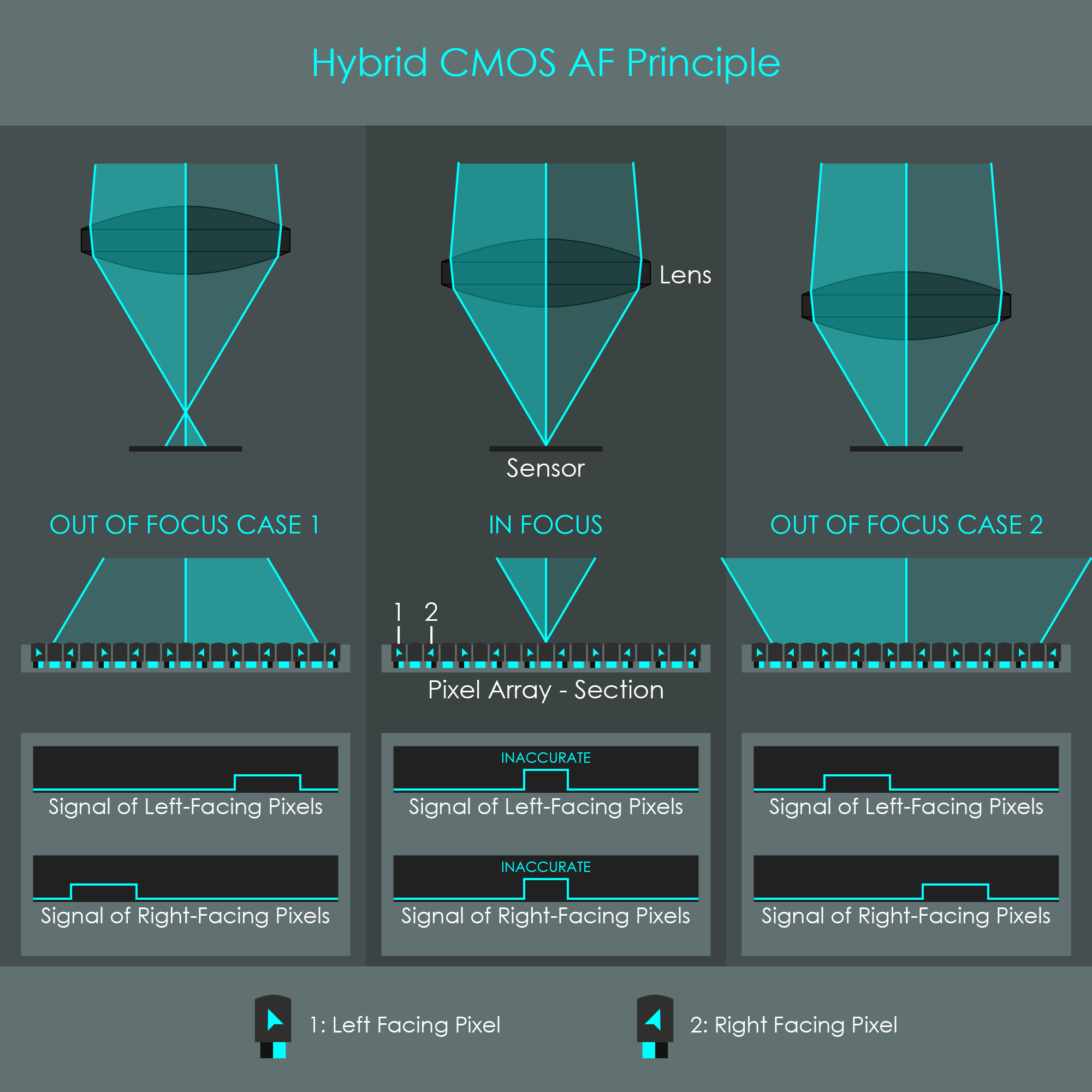
Canon has developed an autofocus technology that combines contrast detection autofocus with elements from phase detection systems. Due to the combination of two oncepts, this technology is called Hybrid CMOS AF. With this new autofocus system, a new sensor technology is used where the active light-receiving surface includes a certain number of photodiodes that are specialized to perform phase detection.

The specialized photodiodes are designed so that they only receive light from one half of the lens. This is achieved by applying a tiny cover plate over one half of the light-sensitive photodiode. As a result, light coming from one half of the lens is effectively blocked from reaching the sensor pixel. Thus, depending on the position of the light cover plate, a photodiode can either receive light from the left half of the lens or from the right half. The illustration shows this special design of a Hybrid CMOS AF photodiode.
Still, such a specialized photodiode cannot perform phase detection individually. It is required to have a relatively large number of these cells integrated into the image sensor with an equal distribution of left-looking and right-looking pixels. Then, the autofocus system compares whether the image produced by all left-looking pixels is in the same position as the image produced by the right-looking pixels. If there is a shift between these images, the system determines both the direction in which the half-images are shifted and the distance by which these are separated. This information is what allows Hybrid CMOS AF to drive the lens to the in-focus position in a very targeted way.

The larger the phase shift is, the further the focal point is from the sensor, thus producing blurrier images. To ensure accurate predictions nonetheless, the layout of the image sensor must be capable of detecting strong phase shifts. There are various implementations of Hybrid CMOS AF sensors ranging from uniform distributions of phase detection pixels up to straight lines of phase detection cells. The image shows a layout where phase detection pixels are placed uniformly distributed on the surface of the sensor.
Although a fair number of phase detection cells is evenly distributed over the image sensor, their resolution is still not very high. For that reason the system is unable to detect slight focus deviations when the in-focus position has almost been reached. Rather, the additional information acquired by the phase detecion component is used to indicate just roughly where the maximum contrast is located so that the lens can move in the right direction from the beginning. For fine adjustment around the in-focus position, contrast detection is performed with the hill climbing algorithm. As a result, Hybrid CMOS AF is a combination of high speed and high precision focus. Not being as fast as a full phase detection system, this invention was still a huge step forward in the development of autofocus systems for mirrorless digital cameras. The diagram shows how targeted the lens can be moved at the beginning, and how hill climbing is performed towards the end.


With the introduction of Hybrid CMOS AF in 2012, initial improvements were soon applied, and quickly there were three generations of Hybrid CMOS AF for Canon DSLR cameras. On the Canon EOS 650D (Japan: EOS Kiss X6 / North America: EOS Rebel T4i), released in 2012, Hybrid CMOS AF I was used. This generation had a small portion (10%) in the center of the image sensor covered with phase detection cells. In the following year, the Canon EOS 100D (Japan: EOS Kiss X7 / North America: EOS Rebel SL1) was released with the Hybrid CMOS AF II installed. This second generation already had 60% of the image sensor covered with phase detection pixels and had an improved performance for autofocusing while shooting video. Finally, the Canon EOS 750D (Japan: EOS Kiss X8i / North America: EOS Rebel T6i) was released in 2015 that had Hybrid CMOS AF III implemented with even further improved video focusing performance, a higher density of autofocus pixels that were distributed in a regular pattern and which was four times faster than the second generation, according to Canon. The illustration summarizes the different generations of Canon’s Hybrid CMOS AF systems.
There are some disadvantages of Hybrid CMOS AF systems. Any left-looking or right-looking pixel has a reduced capacity to record light due to the cover applied over the photodiode. During the capture of the actual photograph, signals from left-looking and right-looking pixels require additional post-enhancement to achieve consistent signal intensity across the entire sensor area. Also, the readout circuitry for left-looking and right-looking pixels is different from regular pixels in order to allow separate readout cycles for phase detection and for the capture of the photograph. Both the implementation of specialized phase detection cells and the specialized readout circuitry increase the production cost for these systems. As Hybrid CMOS AF is still unable to compete with traditional phase detection systems, today’s DSLR cameras still deploy dedicated phase detection sensors, which is why Hybrid CMOS AF is more an improvement for video shooters and live-view photography. With the development of Dual Pixel CMOS AF pixels, Hybrid CMOS AF can already be called an obsolete step in the development of newer on-sensor phase detectors.
Although only being another step in the development of on-sensor phase detection, Dual Pixel CMOS AF is considered revolutionary. Dual Pixel CMOS AF was first introduced in 2013 with the release of the Canon EOS 70D. Again, this technology is based on phase detection performed on the image sensor directly. However, the significant difference between Dual Pixel CMOS AF and the previous developments is that each new pixel can record both halves of the incoming light rays simultaneously and evaluate both signals individually. Therefore, each pixel consists of two sub-photodiodes half the size of a regular photodiode. During the autofocus detection, each sub-photodiode is read out individually by the camera's CPU. On the other hand, during the capture of the actual photograph, both sub-photodiodes are combined to collect as much light as a full conventional pixel would record. The image shows the structure of pixels used for Dual Pixel CMOS AF.
There are numerous advantages of this new pixel structure. Firstly, no cover plates are required to shield one half of a photodiode and therefore the intensity of light falling on a photosite is not reduced by absorption. Secondly, as the pixel sensitivity remains unchanged by the new design, the density of specialized pixels can be increased so the image sensor is filled completely with these phase detection sensors. The image shows the arrangement of pixels on the image sensor.
The increased density of specialized phase detection cells on an image sensor is what allows Dual Pixel CMOS AF to perform phase detection with extreme accuracy as the phase difference can be brought to coincidence by fine increments. For that reason, phase detection can be used as the only autofocus system and contrast detection is not required. Looking at the diagram, the high density of specialized cells is clearly visible and explains why the camera can match the two phases more precisely.
With the contrast detection's hill climbing made obsolete, the autofocus speed is drastically increased with this innovative concept. Over the past decade, Dual Pixel CMOS AF has become the main focusing system in today's mirrorless cameras.