One important task of the camera is to determine the correct exposure that needs to be set when the photo is taken. This measurement of light intensity is called exposure metering. The camera then increases or decreases either the shutter speed, the aperture size or the ISO to ensure that the sensor receives the correct exposure to light.
Today’s light metering systems are the result of an evolutionary development of exposure calculation utilities. The history of light metering dates back almost 200 years. Knowing previous technologies may help to understand the current implementations and their characteristics. Here is a timeline of all major light metering systems applied in photography.
1. Tables: The very first support tools for photographers consisted of exposure tables that have evolved since 1844, almost 20 years after the invention of photography. The tables contained suggestions for exposure durations based on weather and light conditions, time of the year and time of the day, type of subject and film speed. As there were no powerful lenses used at that time, the exposures suggested by the tables typically ranged from several minutes in bright daylight to a good hour in cloudy conditions.
2. Calculators: In 1888, the first exposure calculator – called Actinograph – was constructed by the scientists Hurter and Driffield based on their scientific research. The Actinograph and subsequent calculators were based on the exposure tables, but combined various slide rules and rotating scales. The calculators were the first approach to ease camera operation for photographers.
3. Actinometers: Actinometers were the first instruments not relying on pure experience but actually performing some active light metering. In an actinometer, a small test exposure was made on light sensitive paper. The usual procedure was for the paper to be exposed until its tint matches that of a comparison surface. The time to darken the test paper was then translated into the input values for the shutter speed and aperture value. Actinometers typically had the shape of a pocket watch and became popular during the 1890s and remained so through to the 1920s. Compared with the tables and calculators, the actinometer was independent from environmental characteristics and therefore profited from more versatile applications.
4. Extinction Meters: Another type of active metering tool was the extinction meter. This instrument did not perform a test exposure on photosensitive paper like the actinometer and presented some quicker readings to the operator. Through the viewfinder of the extinction meter, a photographer looked at a row of numbers, arranged behind a celluloid surface that is gradually increasing its opacity. Depending on the particular design, the highest or lowest number just barely visible was determining which light situation was given. This number could then be translated into the required camera exposure settings. Other versions of extinction meters had a pattern visible through the eyepiece, and a control dial varied the amount of light allowed into the device until the pattern could only just be seen. The position on the control then indicated the exposure value. These tools typically had a telescope shape and were rotable to adjust for pre-defined camera settings such as film sensitivity. Extinction meters have been very popular in the 1920s.
1. Selenium Photocells: The first photoelectric exposure meters consisted of a single selenium photocell, a type of semiconductor that became commercially available in the early 1930s. A selenium cell consisted of a steel support plate that had one side covered with selenium, and an ultra-thin layer of gold applied above the selenium layer. Light illuminating the top surface of the selenium cell generated an electric current between the gold layer and the steel plate as soon as these were connected. The more light illuminated the photocell, the more current was generated. That current was tiny but it was displayed by a needle moving over a scale, and a calculator was then used to combine the reading with the film speed to give the result of shutter speed and aperture. An advanced version of this system was called the match-needle meter as described in the previous chapter.
The first selenium light meters were packed into separate handheld devices. The clip-on-camera implementation of the light meter offered a certain degree of integration and was the beginning of exposure automation in photography. The original Canonflex SLR camera (1959) is an example of a camera system with a clip-on exposure meter that was directly coupled with the speed dials. It was not long before cameras around the 1960s had the metering system integrated into the camera body. The Canonflex RM (1962) already had a selenium photocell built into the front of its case. A window at the top of the camera displayed the needle that pointed at the correct aperture that was required depending on the shutter speed that was selected. In operation it was similar to the clip-on meters on the original Canonflex, but the reduced size was another major step in the evolution of exposure metering. With the rapid developments in exposure metering automation, most manufacturers stopped the production of handheld meters until 1970.
Selenium had several favorable properties as photocell material. As selenium cells induce their own current during exposure to light, no batteries had to be used. Furthermore, selenium cells were sensitive to wavelengths similarly to camera film, as opposed to the human eye. Therefore, these types of sensors reacted to light more like camera film and provided quite accurate results. On the other hand, selenium cells would eventually lose capacity over time. With the devices directly integrated in the camera bodies, they were much harder to replace. In addition, selenium photocells often required a significant surface area to generate enough current to drive the meter's needle, often measuring around 40 mm × 40 mm. Around 1960, another material has already been found to eliminate these disadvantages – cells made of cadmium sulfide.
2. Cadmium Sulfide Photocells: Unlike a selenium cell which created current during exposure to light, cadmium sulfide (CdS) photocells were resistors that varied depending on the intensity of light. More precisely, the resistance dropped as the illumination increased. A battery was used to provide an electrical current, and a cadmium sulfide cell varied that current depending on the exposure. Again, a needle was used to display the current on a scale. Compared with selenium cells, one advantage of cadmium sulfide cells was their high durability. The system relied on a current produced by a battery which could easily be replaced once depleted. Also, CdS cells were more sensitive and offered a more accurate reading in low-light conditions.
Their strongly reduced size made them even more suitable for an integration inside the camera body. In particular, the small CdS photocells were the first metering systems that have been installed behind the photo-taking lens so that they would receive the exact intensity of light available on the focusing screen. This technology was called through-the-lens (TTL) metering and brought exposure metering to a whole new level.
Being innovative and small, CdS cells also had some drawbacks. One minor drawback was that they reacted to light similarly to the human eye, which was not the same way most camera films reacted to light. Another major disadvantage was that CdS cells suffered from a temporary night-blindness – an effect where the cell was unable to quickly adapt from a bright scene to a dark one. However, in the early 1970s, camera manufacturers again upgraded their metering systems with a revolutionary new material – silicon.
3. Silicon Photocells (SPC): Silicon photocells combined all the best properties of both selenium and cadmium sulfide cells: Just like cadmium sulfide cells they are small, they offer good performance in low-light conditions, and they are driven by batteries. Like selenium, they rapidly adapt to intensity changes and they react to a wider range of wavelengths. The Canon EF SLR camera (1973) used a silicon meter instead of a CdS meter. Since then, this new material has increasingly gained popularity and widely replaced its predecessors.
4. CPU-Controlled Auto-Exposure Metering: Up to the mid 1970s, electronic circuits were still very limited inside SLR cameras, and almost all of the camera's functions had been carried out by mechanical parts. The Canon AE-1, introduced in April 1976, was the first camera in the world to incorporate a central processing unit (CPU) to control its core operations. These included the auto-exposure system, aperture calculation, shutter control, and others. A silicon cell located inside the viewfinder was used as the light-sensitive element.
This general principle of TTL exposure metering and signal processing by a CPU has remained unchanged right up to the last generations of DSLR cameras. All the advancements in exposure metering technology since the 1970s have primarily concerned on the metering sensors, which have been divided into multiple zones and optimized for color recognition.
Through-the-lens (TTL) metering is an approach for in-camera light metering that was introduced in the early 1960s, and has since been constantly improved and refined. TTL metering is still state of the art for all modern DSLR cameras. The concept is to have a metering sensor built somewhere into the camera body where it can use the light that has passed through the main photographic lens. The actual measurement is typically performed on the preview image which is projected on the focusing screen. Depending on the camera model, the metering system can also use light-sensitive elements inside the autofocus detector which is located in the lower part of the camera body. Regardless of the exact position of metering sensors, the basic principle for TTL light metering is always the same. TTL metering is considered to be the most precise type of exposure metering as it takes into account the focal length as well as individual lens transmission characteristics.
The Canon F-1 SLR, introduced in 1970, had a CdS cell attached to the side of the focusing screen. A beam splitter built into the focusing screen directed a small fraction of light from the focusing screen towards the metering sensor. The beam splitter was designed so that it would only redirect light from the central 11% of the focusing screen surface towards the metering sensor.
The Canon EOS series of cameras, introduced in 1987, have their metering sensor attached to one face of the pentaprism directly above the eyepiece lenses. In this position, the sensor receives light that is emitted by the preview image.
The illustration shows the position of the metering sensor in a Canon EOS-1D Mark IV DSLR camera. The bundle of light reaching the metering sensor has been colored in cyan. Light metering is triggered when the shutter button is pressed halfway. At this stage, the reflex mirror is still in its lower position and reflects light from the photo-taking lens onto the focusing screen. From there, light is emitted towards the pentaprism where it not only reaches the eyepiece but also the metering sensor unit. It is important to understand that white and cyan colored bundles of light are not split by any type of prism or similar optical element, but they are light from the same image point on the focusing screen that fans out into various directions. Rays of light reaching neither the metering system nor the eyepiece are not shown. The photographer views the preview image from virtually the same angle, which makes the positioning of the metering sensor unit seem quite logical.

Light reaching the metering sensor is of lower intensity than light reaching the photo-recording image sensor. The primary reason for this is the use of the semi-transparent reflex mirror that only reflects a certain percentage of the incident light towards the focusing screen while the remaining percentage is intended to reach the autofocus sensor. Another reason for the decreased light intensity reaching the metering sensor is the focusing screen, which scatters the incident light into a wider cone of light. The metering sensor only receives a narrow portion of that cone, which forms a complete but darker image of the preview image on the metering sensor. In order to let the camera determine the correct exposure settings nonetheless, the electronic reading of the metering sensor is typically amplified by circuitry directly integrated into the sensor substrate. This allows the signals to be produced by the metering sensor to be comparable to the exposure on the photo-recording image sensor.
One substantial problem with the single cell layout of earlier metering sensors was that they could only perceive an average light value of the entire preview image that was formed on the focusing screen. Even with the most advanced materials used, a single cell could not differentiate whether the light intensity resulted from an illumination evenly distributed across the entire scene or a dark scene with a small and very bright subject. Although camera manufacturers have established an exposure meter calibration to give satisfactory exposures for typical outdoor scenes, the results have not been as desired if a scene included unusually large areas of highlight and shadow.
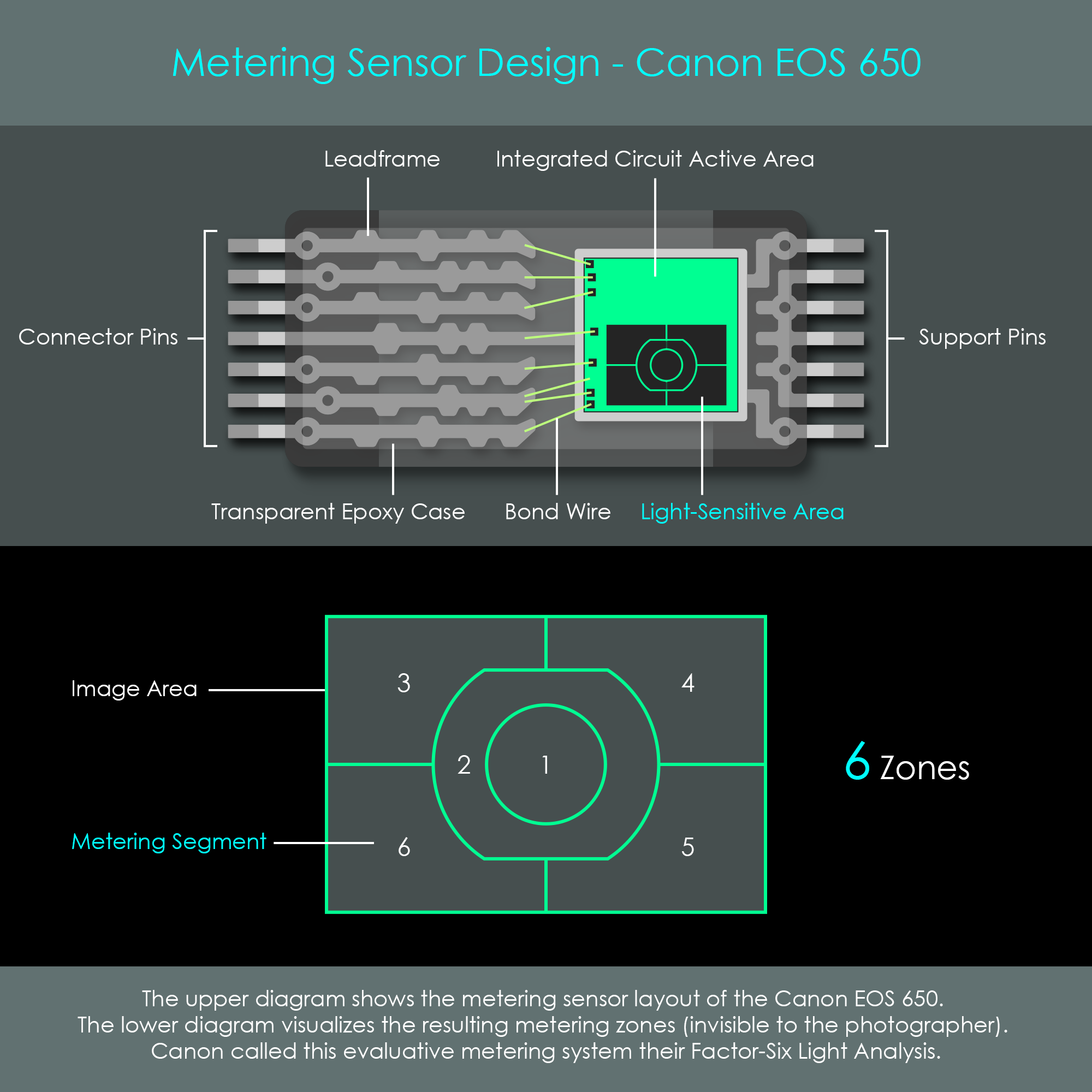
With the release of the Canon EOS 650 in 1987, Canon has introduced a new metering sensor layout. The single-cell metering system has been replaced by a new multi-zone sensor divided into six segments. The segmented SPC sensor is exposed to the light from the entire scene and sends this information to the camera processor. The processor then analyzes the different zones and compares their light intensities in order to identify unusual lighting conditions and to apply some sort of corrections automatically.
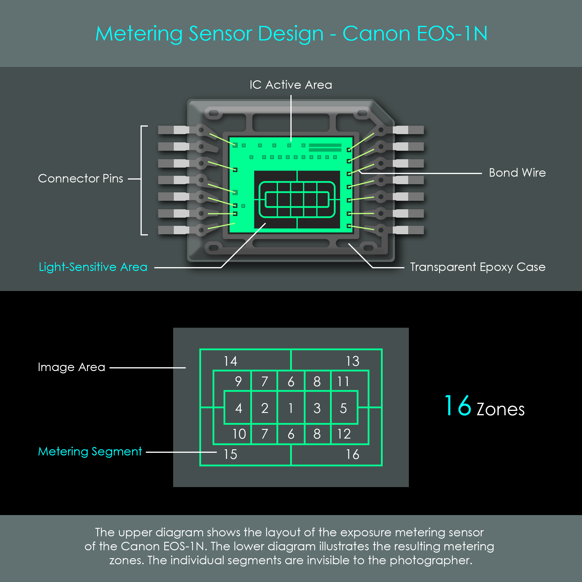
The Canon EOS-1N, released in 1994, already featured a 16-zone metering system including a silicon photocell and integrated circuit. Furthermore, the Canon EOS-1N already used its integrated image processor to enhance the data retrieved from the metering sensor with additional information acquired by various other sensors such as the autofocus sensor. The illustration shows the sensor layout and the resulting metering zones across the scene.
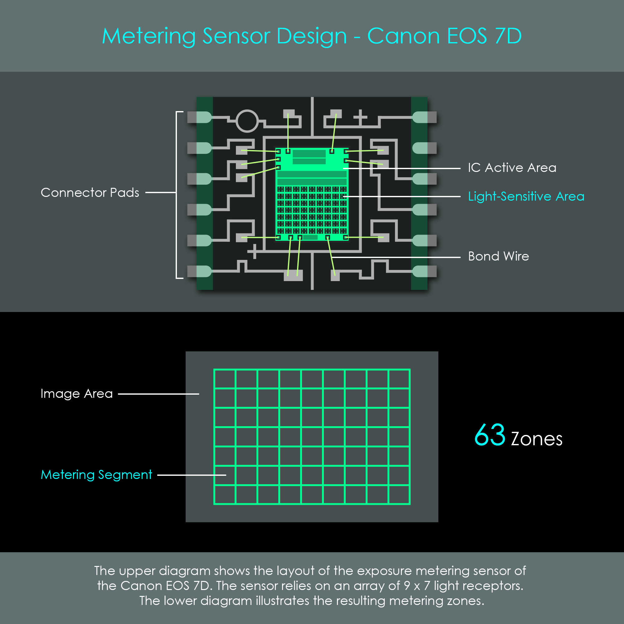
Since then, metering systems have seen continuous improvements on several factors. The most obvious development concerns the number of photosensitive elements. The metering sensor of the Canon EOS 7D, released in 2009, divides the image area into 63 individual zones. However, the true advantage of this metering system is that the sensor is designed to perceive color information to a certain extent. The spectral response of silicon light sensors is significantly higher to long wavelengths than to short ones. In other words, metering systems with regular silicon receptors are more sensitive to red light than to blue light. This in turn has the effect that a camera will tend to underexpose red colored objects, and overexpose those dominated by blue colors. Certainly, this effect can be corrected by the application of a color filter system, but this can decrease metering sensitivity drastically. In order to reduce these types of miscalculations, the metering system of the EOS 7D includes a dual-layer silicon sensor that can differentiate between long and short wavelengths. This type of receptor helps improve exposure accuracy in situations where the scene is dominated by colors at one end or the other of the color spectrum. The illustration shows both the sensor layout and the resulting metering zones of the Canon EOS 7D.
Again, this metering system combines light intensity readings with measurements of the autofocus system. During the exposure reading, the camera processor analyzes the data provided by the single AF points – regardless of the selected AF mode – in order to determine the areas that have achieved focus. Assuming that the focused AF points are likely the ones covering the subject, the metering system prioritizes the metering zones around that area. This system is called iFCL and stands for focus, color and luminance.
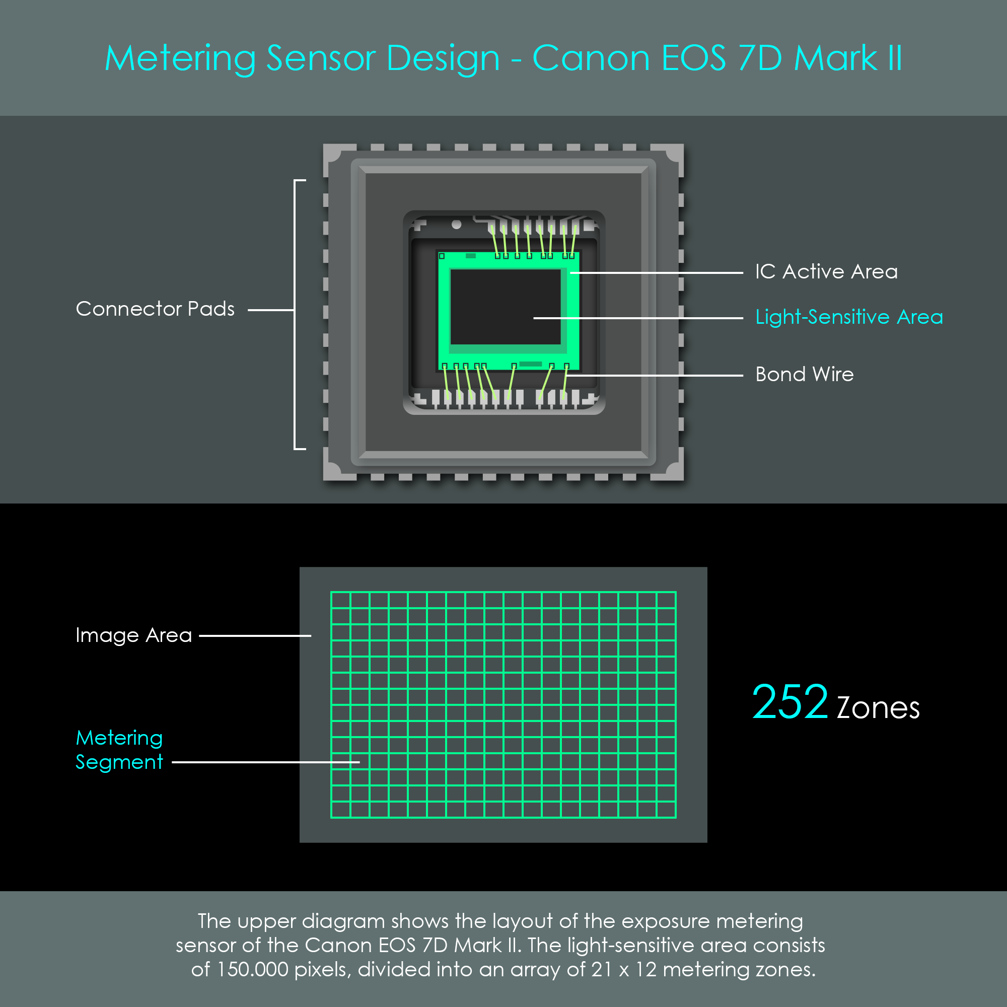
The Canon EOS 7D Mark II, released in 2014, features the most sophisticated metering system at the time that this article was created. The EOS 7D Mark II incorporates a metering sensor with a full color sensor consisting of approximately 150.000 RGB+IR pixels. The processor divides the sensor array into 252 zones, each including around 600 pixels. Both the layout of the pixel array and the full color design are similar to a main image sensor of a camera, only the number of pixels is less on the metering sensor. Still, the resolution on the metering sensor is high enough for the camera's software to detect faces. The diagram shows the sensor layout and the resulting metering zones of the Canon EOS 7D Mark II.