A DSLR viewfinder includes various information systems that keep the photographer informed about the camera settings used, autofocus status, and more.
The use of displays inside the viewfinder has a relatively long history. The fully mechanical SLR cameras manufactured before 1960 typically had no displays inside their viewfinders. Instead, they often relied on external clip-on light meters to determine proper exposure. It was only when electronic sensors were first built into cameras that small display systems have been integrated into the viewfinders.
1960s – Match-Needle Metering Systems: One of the first types of indicators inside SLR viewfinders was a match-needle metering system. This type of system was mechanically linked to the settings of the camera and the lens. The photographer set the film speed (ASA) on the camera, which adjusted the sensitivity of the calculation. As the user adjusted the shutter speed dial on top of the camera, the meter needle reacted and pointed at a certain position on the scale to reflect the required aperture for that specific speed. The photographer then had to rotate the shutter speed dial or the lens aperture ring until a circle (linked to the aperture ring) was aligned with the meter needle (linked to the light sensor). It was a confirmation of correct exposure settings when both the circle position and needle position matched.
These match-needle metering scales had already been installed on the exterior of cameras for a while. With the introduction of the Canon FT QL (1966), this match-needle metering display was relocated into the viewfinder. The camera provided a real through-the-lens (TTL) metering by placing the light-sensitive cell behind the photo-taking lens so that it would read the intensity of light available on the focusing screen. This was achieved by vapor-depositing a semi-silvered beamsplitter surface inside the condenser lens to reflect a fraction of light towards a cadmium sulfide cell located next to that lens. The semiconductor cell provided an electronic metering of light, and the match-needle scale in the viewfinder was used to determine the proper exposure.
1970s – Introduction of Indicator LEDs and Electronic Displays: As the next step in its development, Canon introduced early electronic displays. The Canon AE-1 SLR camera (1976) had a small indicator LED below the match-needle scale in the viewfinder, which lit up to warn the user in case of underexposure settings. The Canon A-1 (1978) took it a step further by incorporating a horizontal LCD display below the preview image in the viewfinder. That display consisted of red seven-segment digits and was designed to indicate the shutter speed, aperture value, warnings in case of incorrect exposure settings, and other information.
With the introduction of the EOS series of Canon cameras in 1987, the earlier needle-based exposure metering systems were completely replaced by digital displays in the viewfinders. Later generations of Canon cameras added a vertical LCD to some of their camera models, and changed the LCD color to green.
1990s – AF-Point Illumination: As autofocus (AF) systems rapidly evolved, the number of autofocus points in the viewfinder also steadily increased. To make the selection of active AF-points easier, Canon introduced various superimpose (SI) display systems to illuminate active AF-points in red. The first Canon SLR camera that featured built-in AF-point illumination within the viewfinder was the Canon EOS 10 (1990).
2000s – Intelligent Viewfinder: A more advanced version of Canon's superimpose display system is the intelligent viewfinder. Introduced in 2009 with the Canon EOS 7D, the intelligent viewfinder allows a variety of guide lines and indicators to be dynamically displayed.
In most digital single-lens reflex cameras, the viewfinder does not only display the preview image on the focusing screen but also additional information on the status and settings of the camera. Of course, all configurations can always be displayed on the main display on the back of the camera, but on-viewfinder screens practically summarize the current settings so that a photographer does not have to take his eye away from the viewfinder. Most entry-level cameras have one horizontal display strip placed directly underneath the preview screen. Conversely, for most mid-range and pro-level cameras, a second display strip is applied vertically next to the preview screen. The illustration shows the viewfinder layout of a Canon EOS-1D X DSLR camera. The aforementioned side-LCD-displays are colored in cyan.
Canon has taken great care at the human-engineering in order to determine the location and arrangement of these displays. Studies had shown that the human eye has a natural tendency to look either to the right or down. This fact was one of the reasons why Canon has installed their side LCDs in these locations.

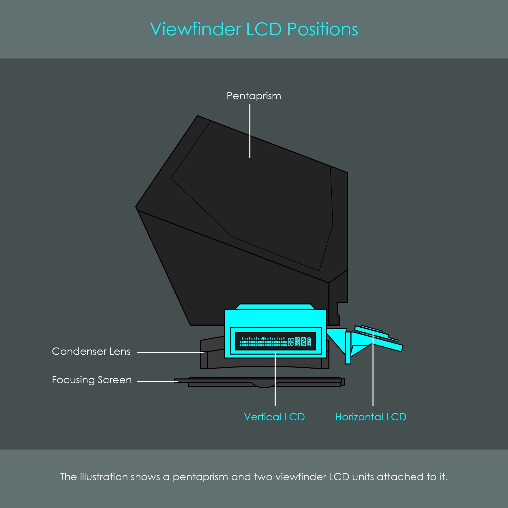
Looking at the technical implementation of the viewfinder screens, these usually consist of liquid crystal display (LCD) panels installed directly under the roof pentaprism. The LCD panels produce a negative image of the desired information and get backlit with LEDs. Although the LCDs have to be in the focal plane for a sharp and focused projection of the information, these LCDs cannot be directly adjacent to the focusing screen due to space limitations. In order to place them in a position equivalent to the focal plane, small prisms are used to increase the optical path length between the pentaprism's lower surface and the LCD. The illustration shows the position of both the vertical LCD (V-LCD) and horizontal LCD (H-LCD).
The tiny prisms reflect light from the LCDs to the lower pentaprism surface. Any information displayed on either LCD is directed through the pentaprism itself and towards the eyepiece. Both LCDs produce images that are flipped as their orientation gets corrected automatically when travelling through the pentaprism. The figure illustrates the projections of light from the side LCD panels towards the eyepiece.

A slightly more advanced stage of development involved display systems that could overlay information directly onto the preview image in the optical viewfinder. Canon calls this type of display their superimpose (SI) display system. While early SI display systems were limited to the illumination of a few autofocus points, the invention of the intelligent viewfinder has greatly expanded the range of features that could be displayed. It is likely due to this continuous optimization of the SI display systems that the optical viewfinder on DSLR cameras remained such a key selling point for so long.
Probably the most useful piece of viewfinder information is a visual confirmation of whether the image is in focus or not. Virtually any digital camera has a number of individual AF-points or small rectangular AF-frames (or a combination of both) in the viewfinder. The positions of the AF-points are typically pre-defined and depend on the camera's underlying autofocus detection system. Entry-level DSLR cameras usually only provide a limited amount of AF-points (up to 9) while professional DSLR models provide a larger set of indicator points spread over the entire preview screen (up to 191 AF-points on the Canon EOS-1D X Mark III, released in 2020).
It is important to understand that AF-points in the viewfinder are only indicators and not autofocus detectors. Each AF-point indicates which part of the image can be used for autofocus detection of the camera. The photographer can select single AF-points or an entire group of AF-points to be active when using the autofocus. If the camera has detected correct focus for a certain area of the image, it generates some form of feedback for the photographer to confirm the in-focus condition. On Canon DSLR cameras, this feedback is given both by a beeping sound and a brief red flash of the the corresponding AF-point. Over the past few decades, Canon has developed several innovative methods for illuminating the AF-points.
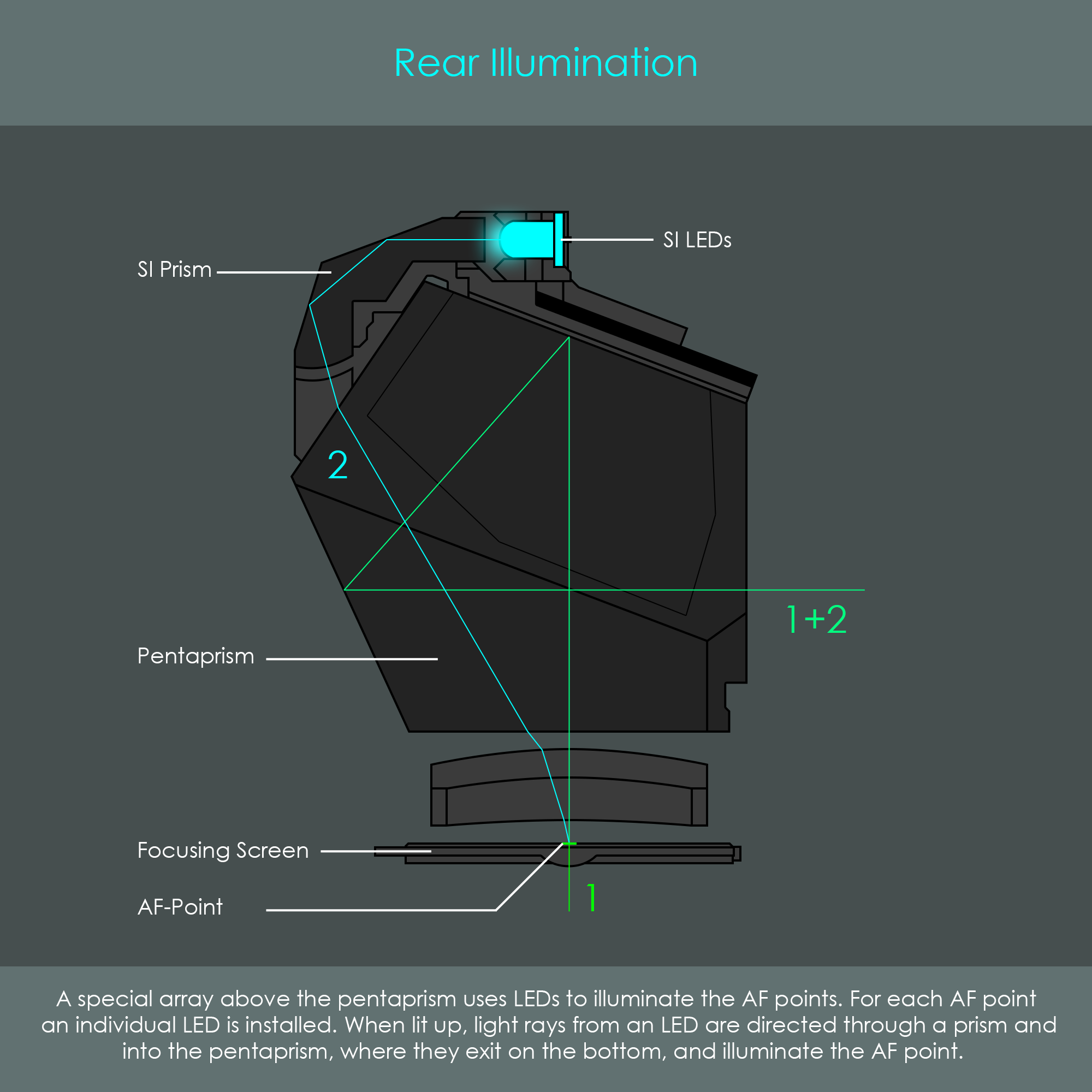
The use of discrete light-emitting diodes (LEDs) to illuminate AF-points looks back on a relatively long history. This technology has already been used for analog SLR cameras in the early 1990s. This type of visual feedback system consists of an array of light-emitting diodes (SI LEDs) installed above the roof pentaprism and a light-guiding prism (SI prism). Light from an LED is passed through the SI prism to the rear surface of the pentaprism. As light continues to travel through the pentaprism and through the condenser lens, it eventually illuminates the AF-point that is engraved into the focusing screen. The AF-point in turn reflects the light towards the pentaprism where it is directed towards the eyepiece. This effect is what the photographer will perceive as the AF-point lighting up.
In viewfinders of these early cameras (for example Canon EOS-1N, 1994), the AF-points are usually arranged in a horizontal line in the middle of the focusing screen. Due to this simple layout, the SI LEDs can also be arranged in a vertical configuration. A pinhole mask is applied in front of the LEDs to minimize their beam angles in order to make sure that each LED only illuminates its intended AF-point. The illustration shows the optical system inside the viewfinder of the Canon EOS-1N analog SLR, which features five AF-points in a row. It should be noted that this lateral cross section can only display the center LED illuminating the center AF-point. The remaining LEDs as well as the remaining AF-points are located outside (2) and inside (2) the drawing plane. If you want to read more about the AF-point illumination system of the Canon EOS-1N, here is an even more detailed presentation of the technology.
There is a variety of other implementations of AF-point illumination systems that use discrete LEDs. In some models, for example, light is directed onto the reflex mirror to illuminate the AF points from below.
A slightly newer technology is the use of an LCD projection system. This technology does not require to have AF-points or AF-frames engraved into the focusing screen, and therefore no AF indicator can be seen in the viewfinder when the SI display system is inactive. The concept behind the LCD projection system is not to have physical AF-points reflect light from a light source behind the pentaprism, but to create the illusion to the observer as if red AF-points would appear on the focusing screen.
The LCD projection system is located in close proximity to the pentaprism and includes a light source (SI LED) and a transmissive liquid crystal display (SI LCD). The LCD acts like a digital mask that can either block all light from the LED or allow certain areas to become transparent. When a particular AF-point is lit up in order to confirm correct focus, the LED emits light and the LCD partially turns off to allow a small beam of light through. A mirror reflects light beams from the LCD down where a light combining unit will again reflect them towards the eyepiece, effectively superimposing the viewfinder image with the image of the LCD. The illustration clarifies the configuration of an LCD projection system by showing the cross section of a Canon EOS-1D Mark IV viewfinder.
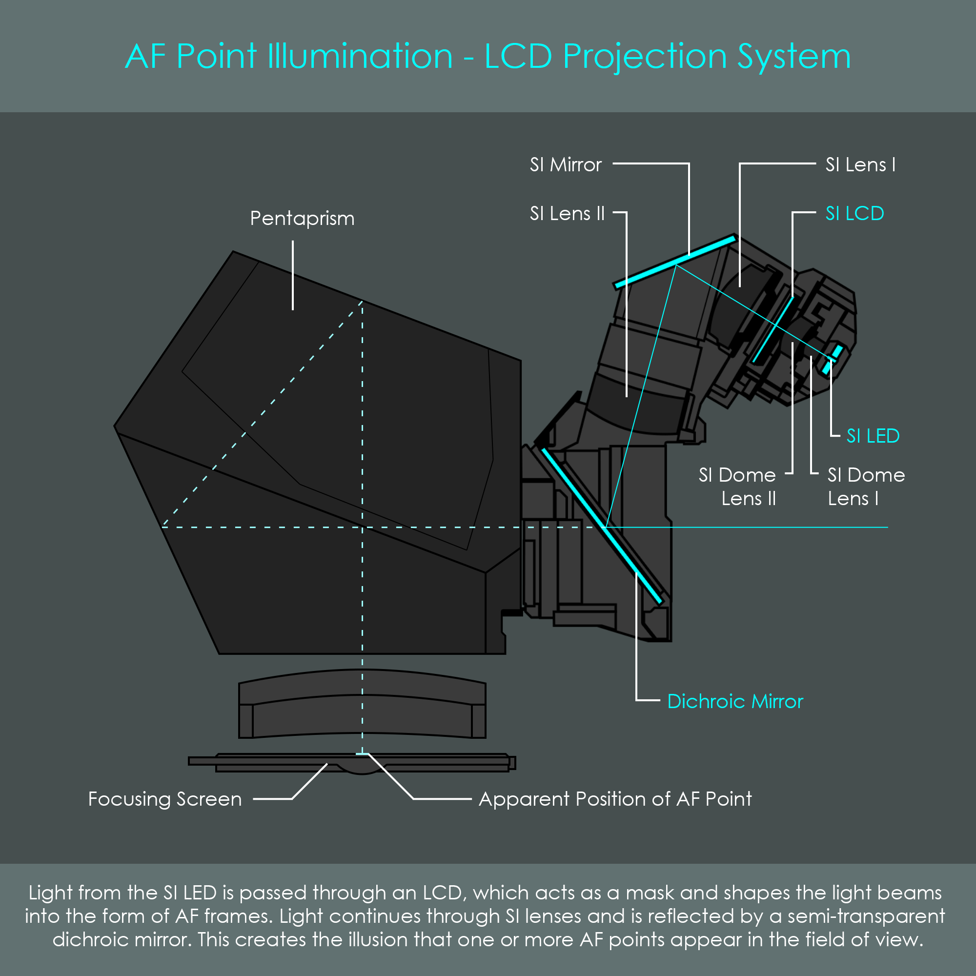
Here is a closer look at some of the components:
If you want to read more about this LCD projection system, here is an even more detailed presentation of the technology.
An intelligent viewfinder is Canon's most advanced concept used to display photographic information in optical viewfinders. The intelligent viewfinder uses a transmissive LCD screen to display a variety of indicators and shapes such as AF-points or customizable grid lines. Information on the LCD is normally turned off so that it does not obstruct the preview image.
The Canon EOS 7D was the first DSLR camera to be released with an intelligent viewfinder to provide a customizable overlay screen. The EOS 7D has a set of 19 AF-frames but does not display all of them simultaneously as they would cover a large portion of the viewfinder image. The camera only displays the AF-frame that has been selected for autofocus, and the surrounding AF expansion points if these are used. The EOS 7D's intelligent viewfinder can also activate two versions of grid lines. Its successor, the Canon EOS 7D Mark II, uses an improved version, the intelligent viewfinder II, to display even more information, including a digital level and other photo-taking information (flicker warning, selected file format, battery charge status, etc.).
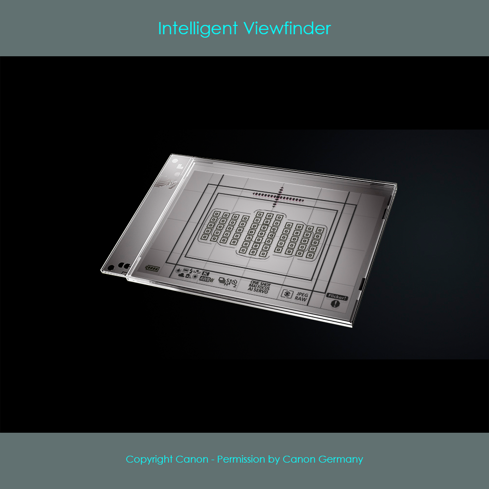
In order for the intelligent viewfinder's information to be focused and clearly visible, the LCD unit is installed directly above the focusing screen where the preview image is formed. In contrast to the aforementioned types of LCD panels, the intelligent viewfinder LCD is configured to display a positive image of the information. This means that the LCD is transparent in general but blocks light in areas where information is displayed. Also, the intelligent viewfinder LCD is much larger in size than previously discussed LCDs as it needs to cover the entire focusing screen. The image shows the transmissive LCD element of the intelligent viewfinder II.
In low-light conditions, the intelligent viewfinder lights up all currently shown information to improve visibility. The intelligent viewfinder can also light up in red when the active AF point is selected or when focus is acquired, depending on the camera settings.
To be able to illuminate features displayed on the intelligent viewfinder, two pairs of red SI LEDs are attached to opposite sides of the LCD screen. Light from these LEDs is passed into the sides of the LCD (via small light-guide optics not shown in the illustration). Light introduced from the SI LEDs interacts with the liquid crystals and lights them up. These glowing LCD crystals in turn will emit light perpendicularly towards the large LCD surface, allowing it to exit the LCD on the large surface. This light travels through the viewfinder system in the usual way and appears as the intelligent viewfinder flashing up its information in red. The image summarizes the principle of operation. If you want to read more about the intelligent viewfinder, here is an even more detailed presentation of the technology.
