A viewfinder in general is a system that allows the photographer to view the subject or scene before the photo is actually taken. Such a preview of the photo is essential to find the perfect perspective, composition and to determine proper focus.
Over the past 200 years of photography, several different implementations of viewfinders have evolved. One type of viewfinder that was very common on cameras from the 1960s (such as Polaroid cameras or Canon's Canonet series of cameras) was an optical viewfinder that had a separate opening in the case to accommodate some viewfinder lenses. These viewfinder lenses were completely separate from the actual photo-taking lens of the camera. Therefore, they did not capture any light from the main photographic lens, and therefore did not preview the scene in the perspective of the photo-taking lens. They rather tried to imitate the field of view the photo-taking lens would produce. In fact, however, these separate viewfinders actually quite often suffered from parallax error. A parallax error occurs when an object placed in front of a background is seen from different positions. The slightly different angle inherent with another position will sometimes result in a very different impression of the scene. Applying this principle to photography, it means that the scene may actually look pleasing on the separate viewfinder but the final image doesn't exactly turn out as expected.
You can easily get a feel for the parallax error if you raise one arm and turn up a thumb. Then, close the right eye and look at the composition of background and your thumb representing a subject to be photographed. Then, look at the scene with the right eye only while not changing the position of your arm and thumb. You will notice that the composition of background elements and your thumb has changed, eventually resulting in background elements to be covered by the foreground or large gaps between the subject and other objects.
Another challenge of separate viewfinders was that they often had one focal length only. If the main photographic lens was a zoom lens that was used to change the focal length, the separate viewfinder not longer provided a realistic preview. Some improved versions of separate viewfinders had parallax-corrections and features to align with the focal length of the photo-taking lens. However, there were more limitations that could not be corrected in a reasonable way, such as the lack of previewing the scene with photographic filters applied to the main lens.
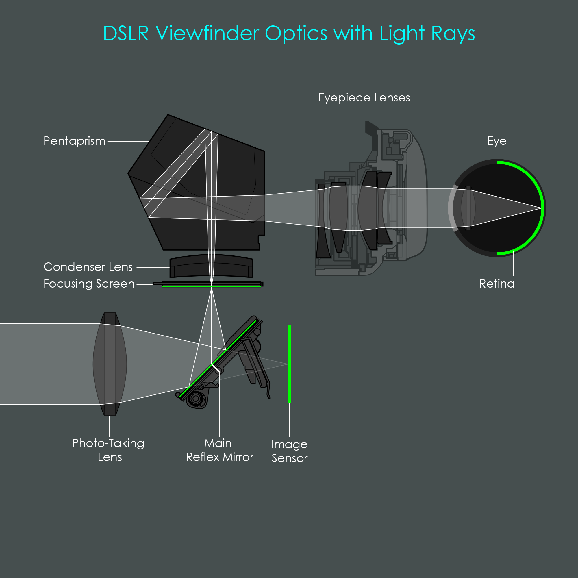
The viewfinder unit as used in DSLR cameras consists of a focusing screen, an optional condenser lens, a roof pentaprism, and various lens elements for the eyepiece. The unique feature of a DSLR viewfinder is that it uses the light that passes through the main photo-taking lens. For that reason, the camera doesn't require an additional opening for the viewfinder. While the mirror is in its lower position, light gets reflected to the focusing screen where it forms an image. The translucent focusing screen emits that light from its top surface and projects it through the condenser lens into the roof pentaprism. In there, the image gets flipped vertically and horizontally, and is then passed through the eyepiece lenses towards the photographer's eye. This configuration with only one photographic optical system is also the reason why these types of cameras are called single lens reflex cameras.
This optical setup prevents DSLR cameras from being affected by parallax error. The photographer can look at a preview image that does not differ from the scene the image sensor will record. This solution also covers zoom lenses that can change their field of view. DSLR cameras also have a number of very sophisticated auxiliary devices incorporated into the viewfinder unit. The following chapters will explain each of these in great detail.
Please note that, for illustrative purposes, the photo-taking camera lens is typically depicted in the following illustrations as a single glass element. In reality, camera lenses consist of a complex arrangement of numerous lens elements of varying sizes. If you are interested in the inner workings of Canon lenses, you can find more detailed information about Canon Lens Technology here.
The first illustration visualizes how a bundle of central rays of light is passed through the viewfinder system. These rays – indicated here by white color – originate from the center point of the photographic scene and do therefore only contribute to one single image point of the viewfinder's preview image. Consequently, this single point does only fall on a single point in the photographer's eye (and will similarly only fall on a single point on the camera's image sensor).
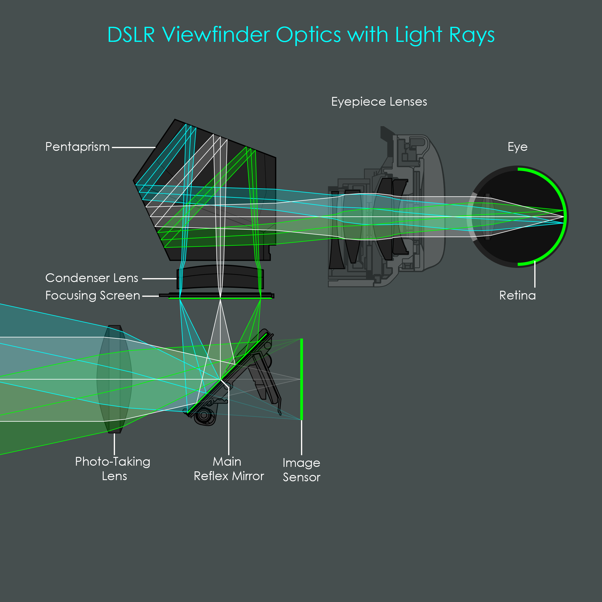
This second illustration adds two bundles of edge rays. These rays – colored cyan and green – have been emitted from the edges of the photographic scene and do therefore contribute to the outer edges of the preview image. These are just the rays of light from the extreme points. All other points in the scene would produce an infinite number of additional rays of light.
Although a DSLR camera uses the light from the main photographic lens to generate a preview image in the viewfinder, you are not actually looking through the photographic lens when holding the viewfinder at your eye. When you look into the viewfinder, the preview image you see has been formed on an acrylic plastic screen inside the viewfinder assembly, called the focusing screen. The focusing screen is a translucent thin plate that has a very fine-grained matte surface on the lower side and that is placed exactly at an equivalent focal plane. This matte surface is where the light rays from the photo-taking lens (after being redirected by the primary mirror) form an image. In the past, this focusing screen was often made of glass that has been roughened on one side by sandblasting or grinding, hence the focusing screen is also referred to as ground glass. Since the 1980s, the matte surface was usually created by laser-etching the lower surface of the plate, like on Canon's laser-matte focusing screens.
The diagram shows a conceptional version of a viewfinder with no focusing screen installed. For reasons of simplification, the reflex mirror, pentaprism, eyepiece lenses and other components are not shown in this illustration. Therefore, no reflections are shown, and all components are arranged in a linear way. The opening on the right represents the eyepiece opening that the observer holds against his eye. The focusing screen is absolutely necessary for the following reasons:
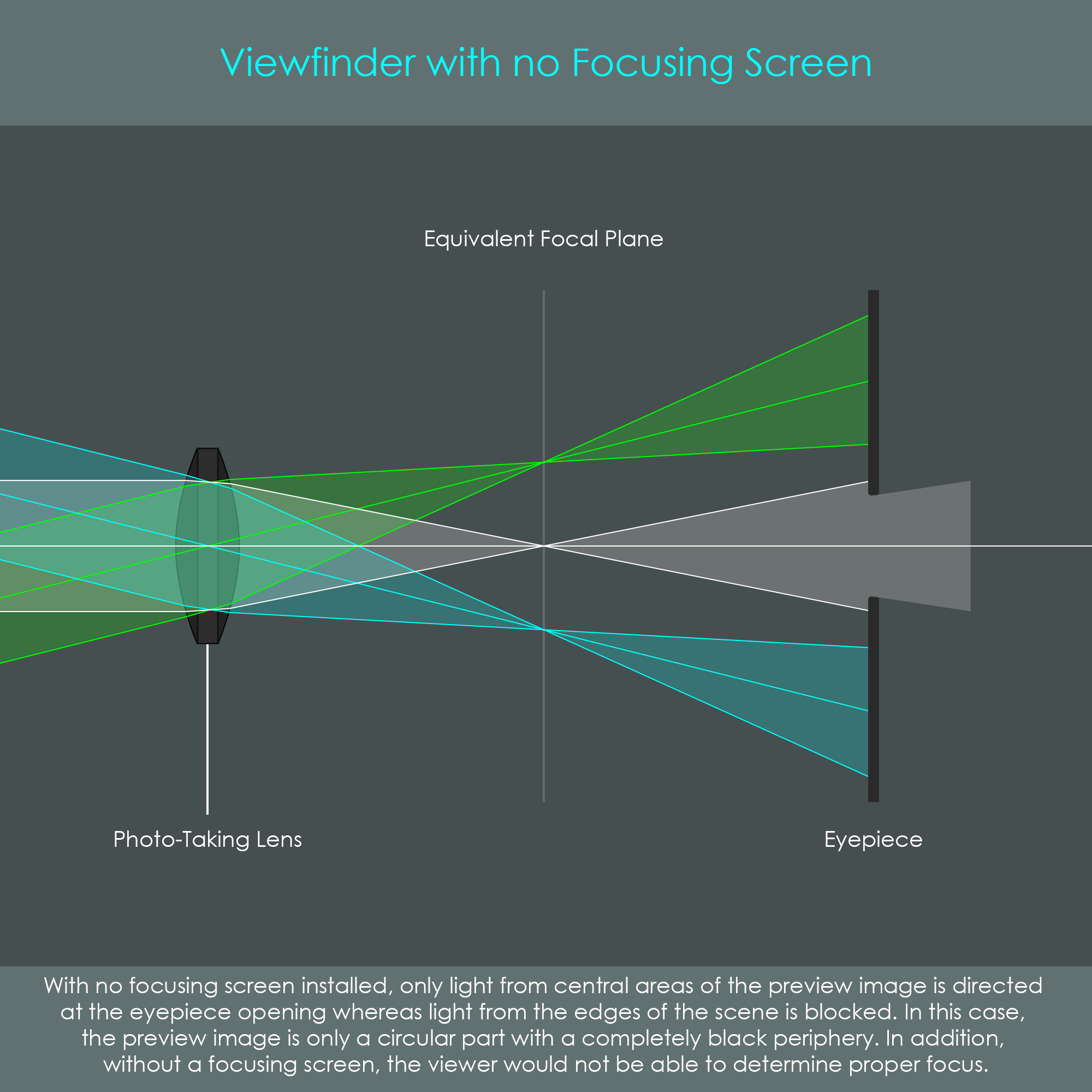
In order to obtain a complete preview image, a focusing screen is placed inside the viewfinder at an equivalent focal plane which has an identical distance from the photo-taking lens as the image sensor.
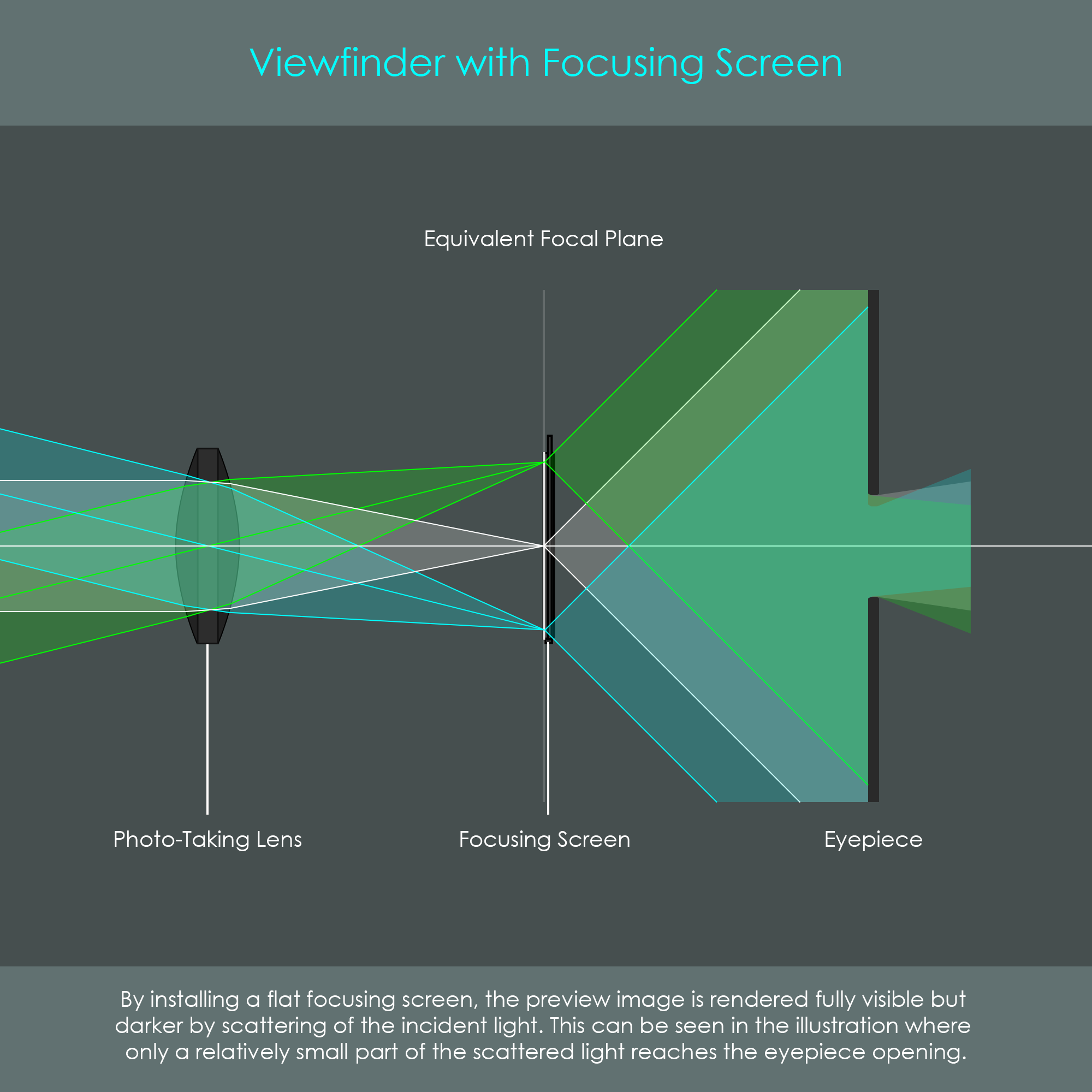
The diagram shows how the focusing screen works: The matte screen of the plate acts as an optical diffuser that scatters light rays. This scattering gives some rays of light a new direction and ensures that even the light rays coming from the outer edges will reach the eyepiece. The image created on the focusing screen acts like a new subject that the photographer can directly view and assess. In addition, with this configuration an incorrectly focused photo-taking lens would show a blurred subject on the focusing screen.
The two functions of a focusing screen can be summarized as follows: Firstly, it causes a diffusion of light so that even the edge rays of light can reach the eyepiece. Secondly, it allows the photographer to assess the image as it will be recorded by the image sensor (including composition, exposure, and focus condition).
It should be noted that the viewfinder's preview image is still relatively dark in our illustration. This is revealed by the path of light: Light emitting off the focusing screen is spread in such a wide angle that most of the light fails to reach the eyepiece. Over the past decades, camera engineers have developed several effective methods for increasing the viewfinder brightness.
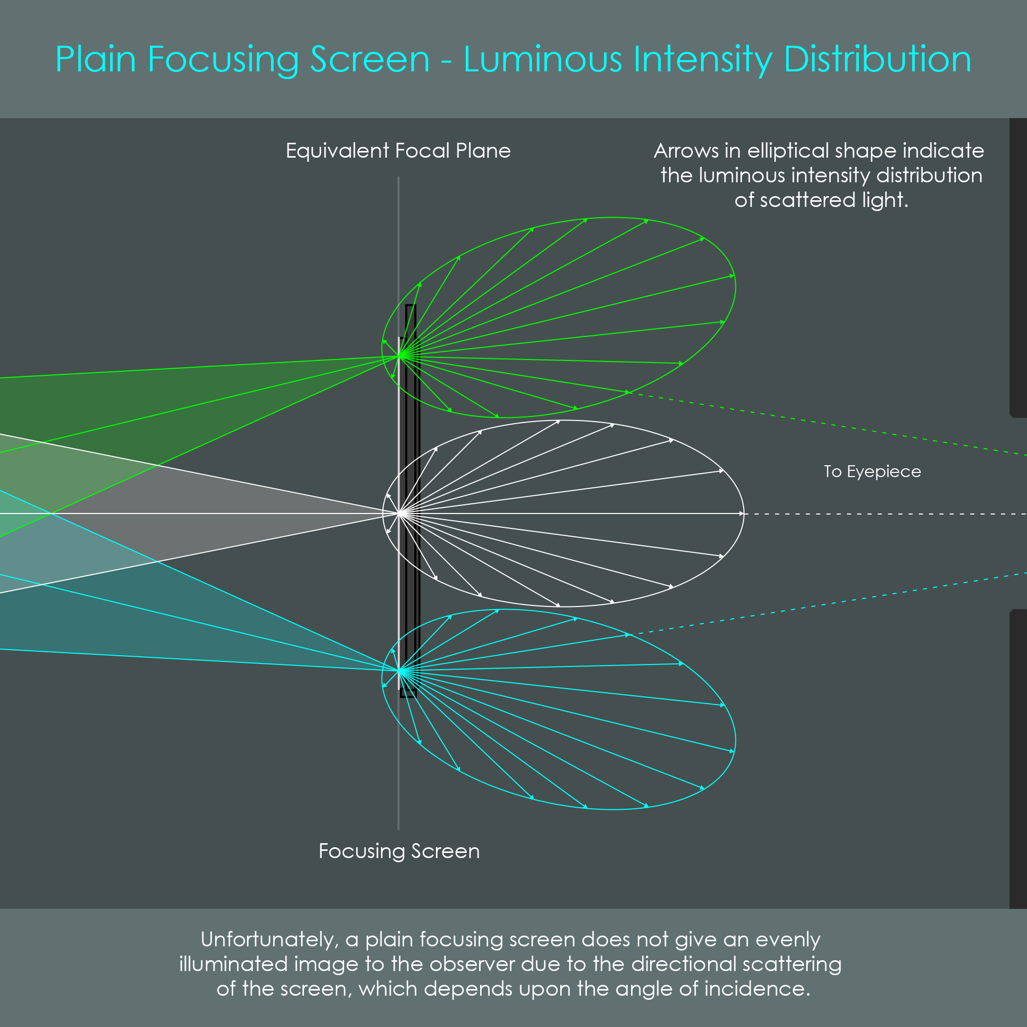
Unfortunately, a plain focusing screen does not give an evenly illuminated image to the observer due to the polar properties or directional scattering of the screen (indicated by the elliptic lines), which depend upon the the angle of incidence. For that reason, most of the oblique illumination is lost to view. The effect is of a bright central area with peripheral darkening.
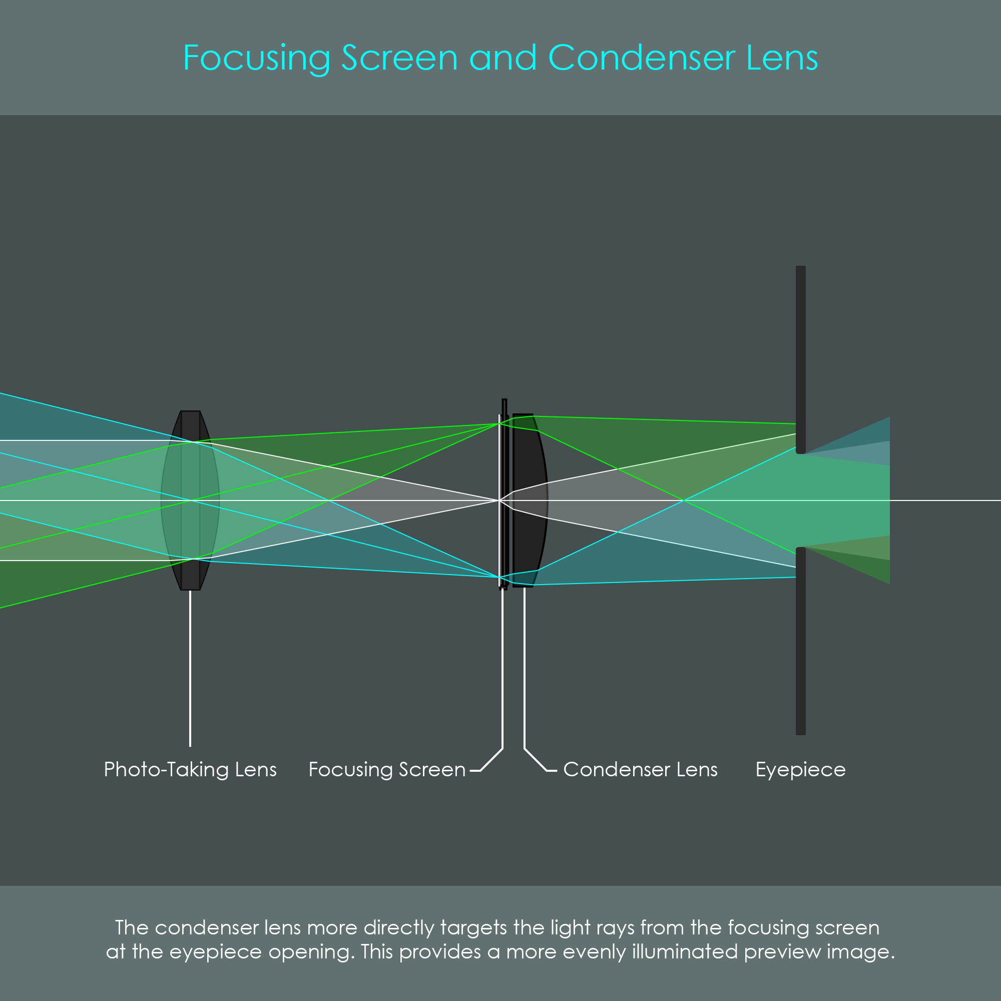
The introduction of a plano-convex condenser lens (acting as a field lens) into the viewfinder brings some noticeable improvements to the brightness of the preview image. A condenser lens is a converging lens that reduces the angle at which the light rays diverge after being emitted from the focusing screen. This aims the bundles of light more directly at the eyepiece, and therefore reduces the proportion of light that is lost by hitting internal walls. The result is a viewfinder with a brighter and more evenly lit preview image, especially in the edge regions. One disadvantage of a traditional glass condenser lens is, however, that it may contribute quite significantly to the overall weight of the camera and to the size of the viewfinder apparatus. For that reason, today's DSLR cameras do not use glass condenser lenses but have Fresnel lenses installed.
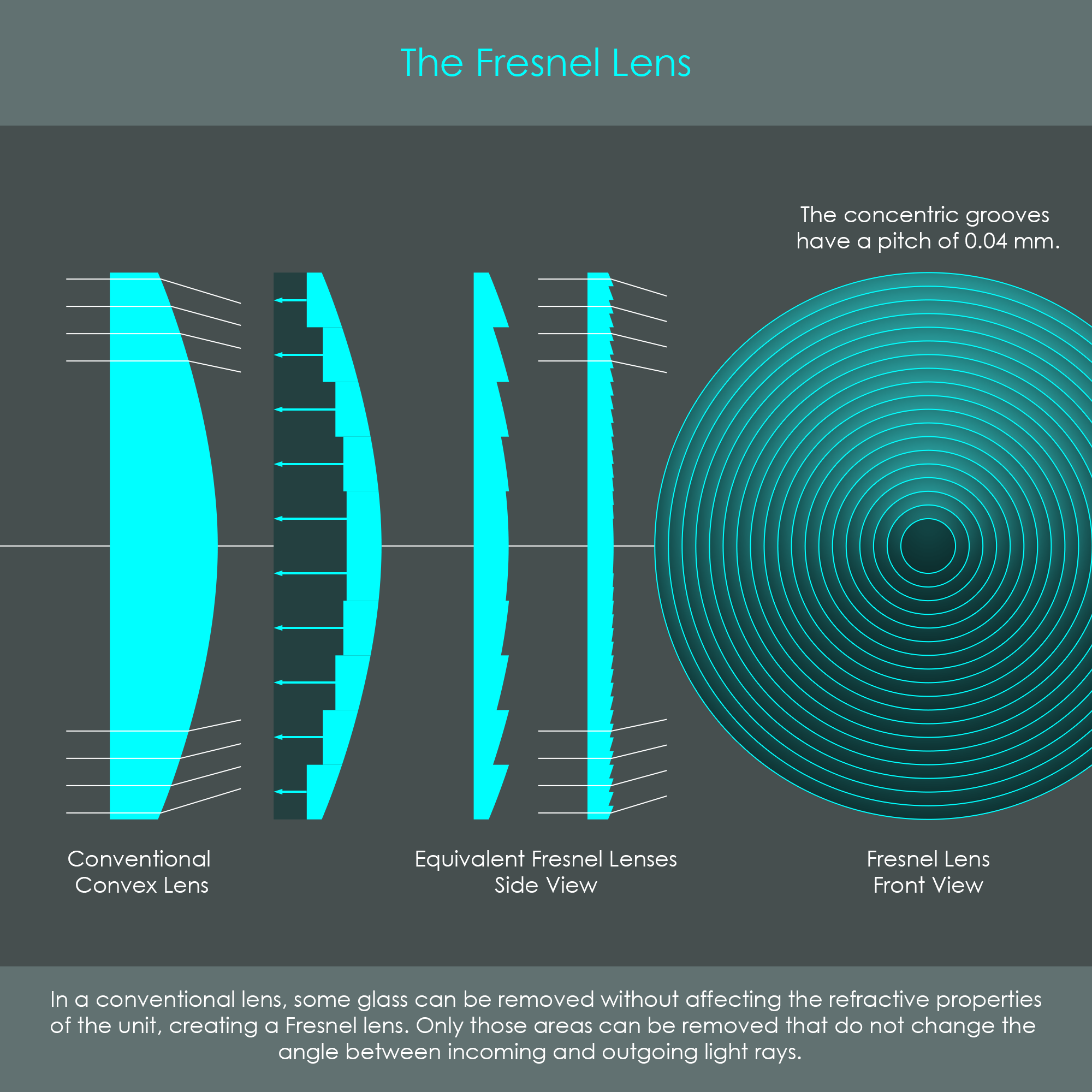
A Fresnel lens is a type of lens with a very characteristic shape but the same refractive properties like a conventional glass lens. Every conventional lens has some material inside that does not contribute to the refraction, and therefore it can be removed without affecting the overall functionality of the lens element. This gives a Fresnel lens its unique shape, a flat body that has concentric rings when seen from the front. These thin lenses are also called diffractive lenses, and they are typically composed of a plastic substrate in which the concentric grooves are molded on one side. The illustration shows how the Fresnel lens is much thinner than the conventional glass lens while maintaining an identical refractive power than the conventional unit. Two significant advantages of Fresnel lenses are their much reduced weight and their ultra compact design.
Canon also uses these optical elements in some of their photographic lenses. You can read more about these specialized and rare diffractive optics lenses here.
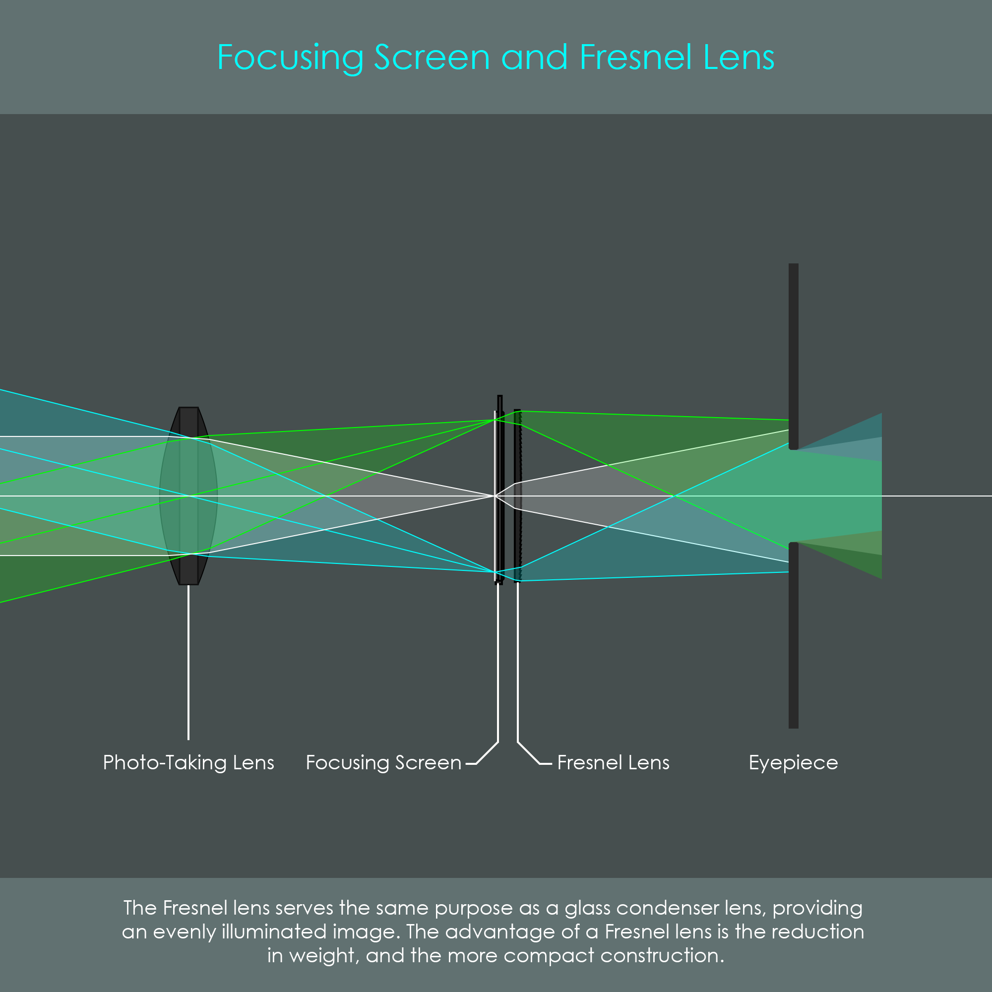
In the viewfinder, the Fresnel lens is either attached to the shiny side (pentaprism side) of the focusing screen as a separate piece, or it can be directly integrated in the focusing screen. It can be seen in the diagram that the Fresnel lens has an identical effect on the viewfinder brightness by narrowing down the light bundles that get emitted from the focusing screen towards the eyepiece.
The use of separate Fresnel lenses dates back to the era of manual focus SLR cameras, such as the Canonflex RP camera, which was introduced in 1960. The focusing screen inside that camera actually consisted of two pieces: The matte glass plate and a separate Fresnel lens plate.
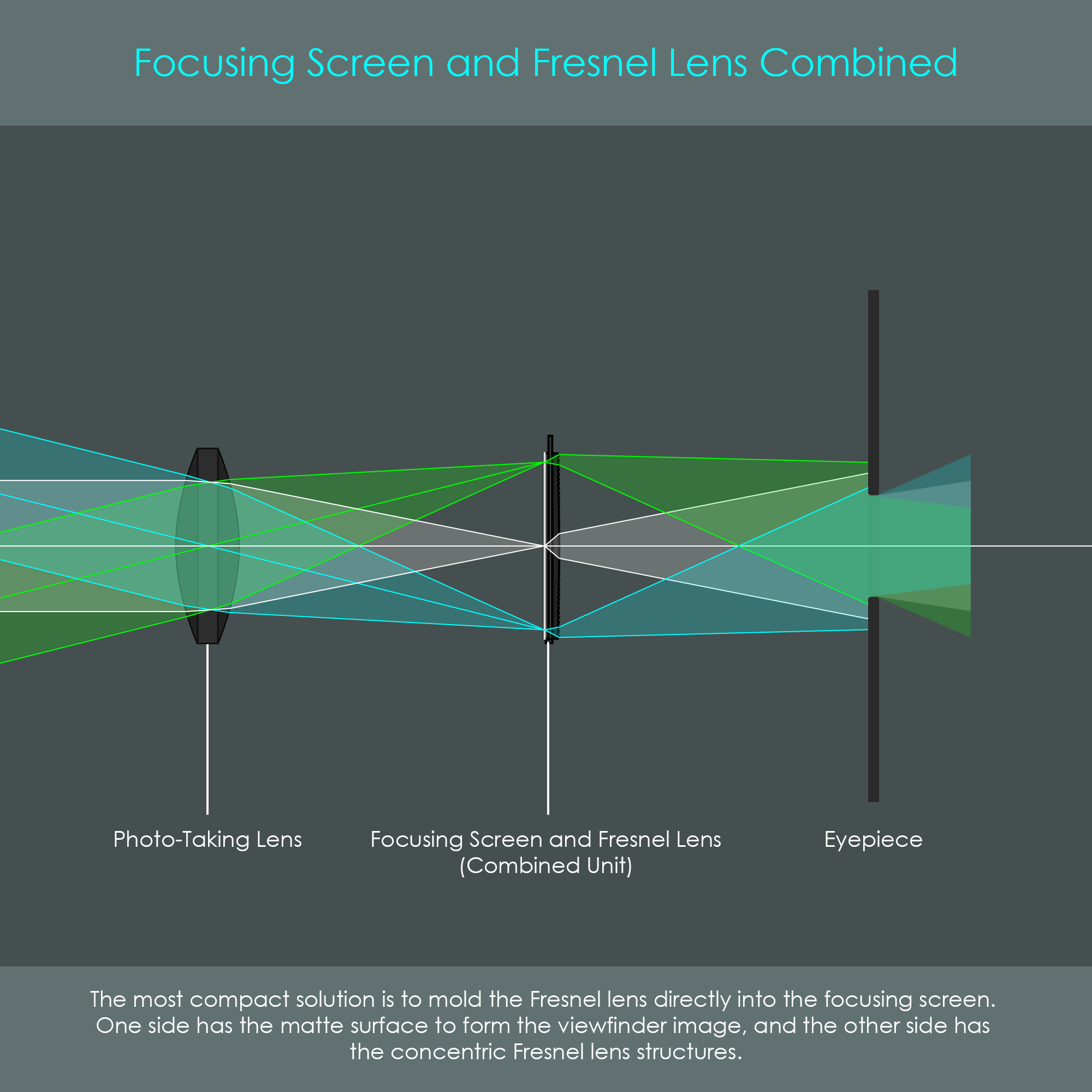
The illustration shows the most common type of condenser lens: A Fresnel lens that is directly molded onto the surface of the focusing screen. This again reduces both weight and size of the camera while effectively improving viewfinder brightness.
Canon began using focusing screens with the Fresnel lens directly molded into the screen in the 1980s. The first camera using this new focusing screen technology was the Canon New F-1, released in September 1981.
As development progressed, Canon also introduced variants in which the Fresnel lens is molded into the underside and the laser-matte surface on the top of the focusing screen.
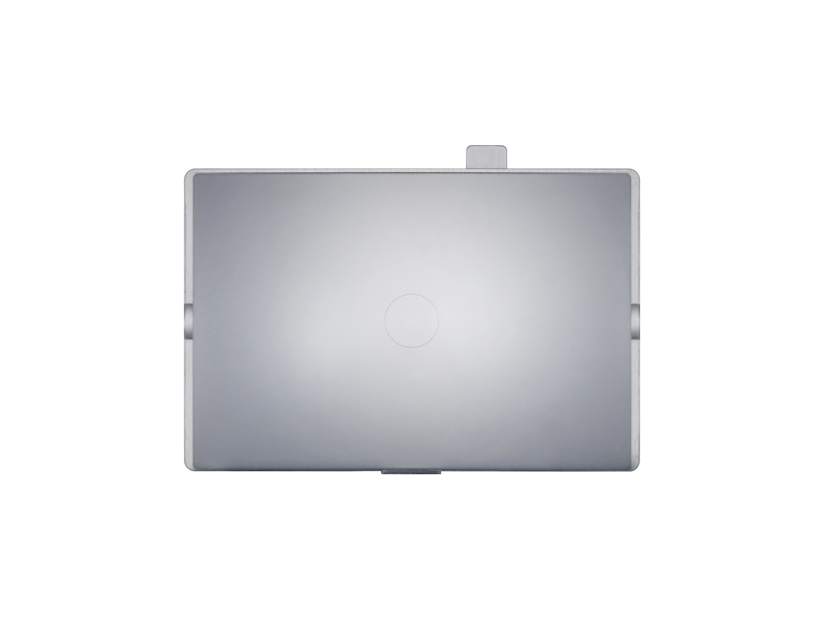
This is a photo of the focusing screen inside a Canon EOS-1D X DSLR camera. The focusing screen is made of a thin acrylic plate with a laser-matte surface on the bottom surface and a Fresnel lens structure on the top surface.
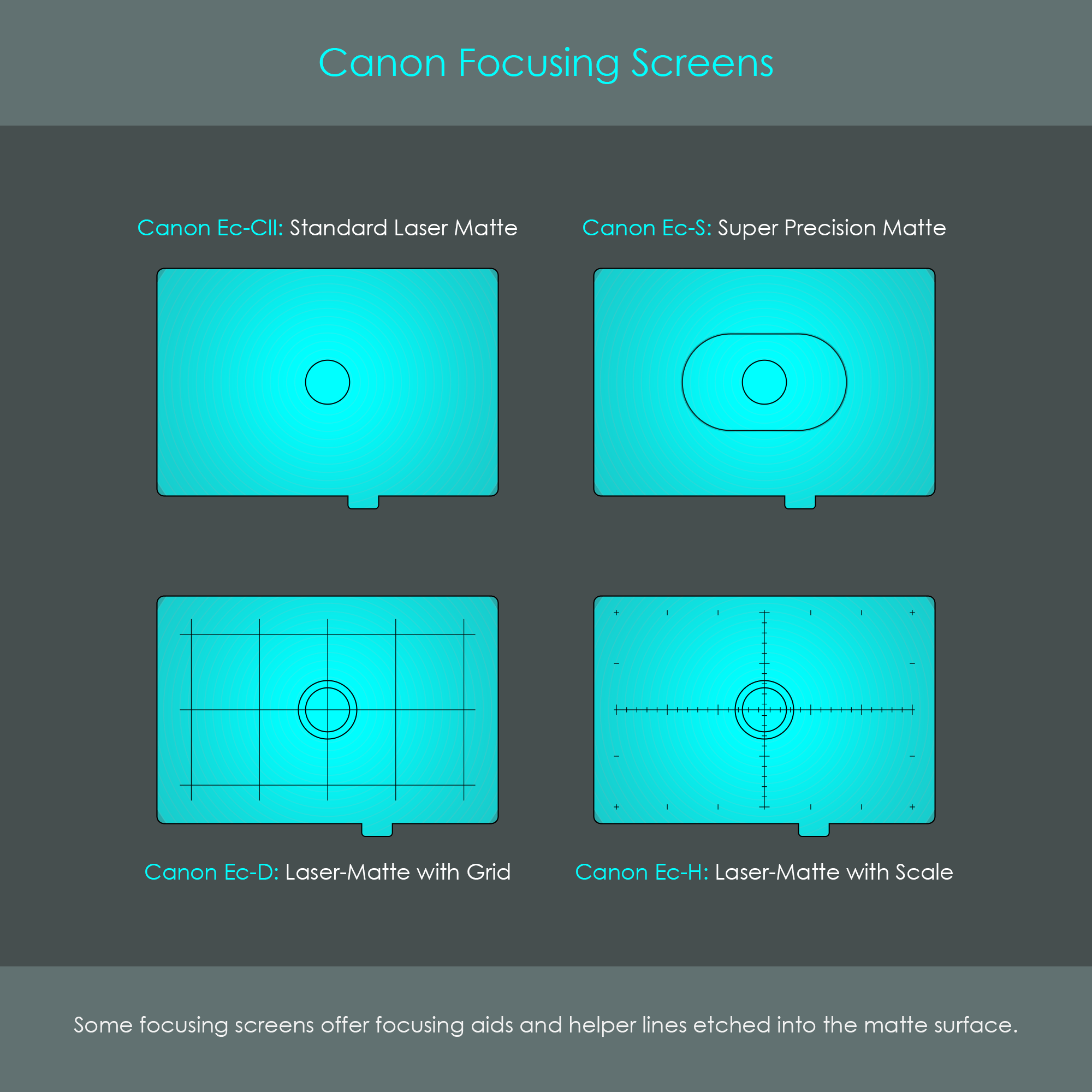
Over the past decades, Canon has introduced a variety of focusing screens. Most of these have certain helper guidelines or focusing aids engraved. While split-prisms are very useful for manual focusing, screens with scale lines are often used for macro photography whereas screens with parallel grid lines are ideal for architecture photography. The illustration shows four of those focusing screens. The concentric rings of the embedded Fresnel lens are much smaller and tighter in reality and are therefore invisible to the eye.
A pentaprism is a key optical element that ensures the correct orientation of the preview image in the viewfinder. The name pentaprism results from its five-sided shape (the Greek word 'penta' means five) and its primary function as a reflecting prism. Although it has five sides, there are only two sides used for the reflection of the image while two sides are required to let light in and out of the glass body. One last side is not optically used but is kept flat for the sake of compact size. Some requirements for the pentaprism include that it maintains image brightness and reflects light without introducing any type of distortion.
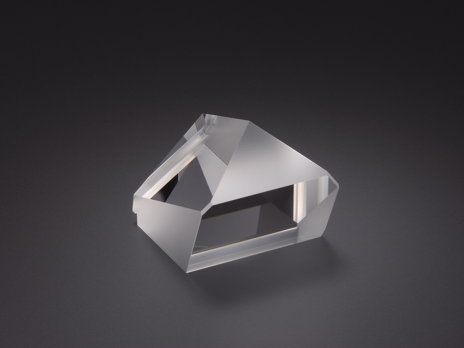
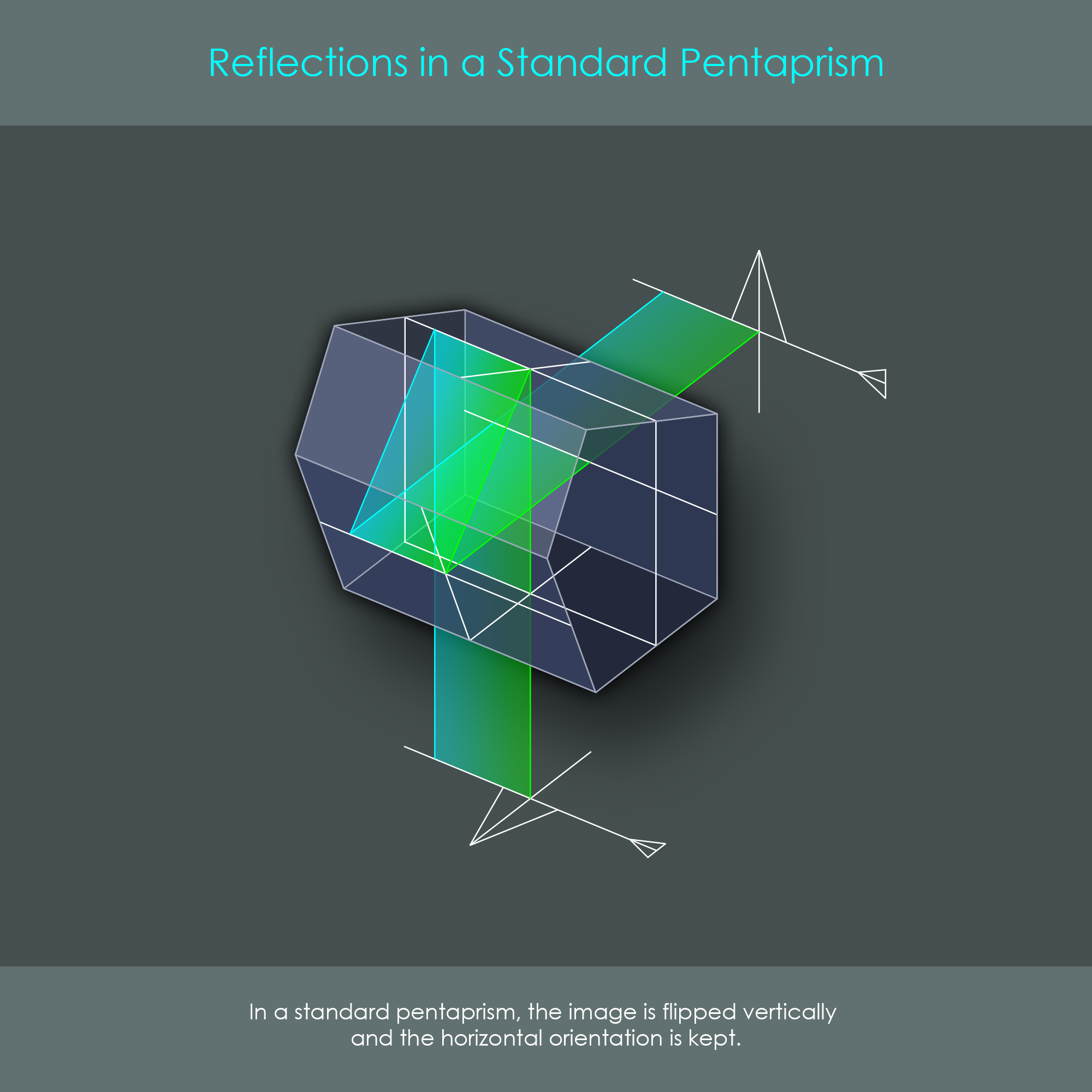
In a regular triangular prism, light can enter on one side (called face) and exits the prism on the opposite face. In a reflecting prism, light will not be allowed to exit certain faces but rather is reflected two times and stays inside the prism until it can finally exit one face. The reflections inside the prism are not caused by total internal reflection that would occur if the beams were incident at an angle less than the minimum angle for total internal reflection (critical angle). Instead, the two faces are coated to provide mirror surfaces. The diagram shows how the incident beam reflects twice inside a regular pentaprism. Note that this type of pentaprism is not used in photographic cameras but was only used in this illustration to explain the basic principle.
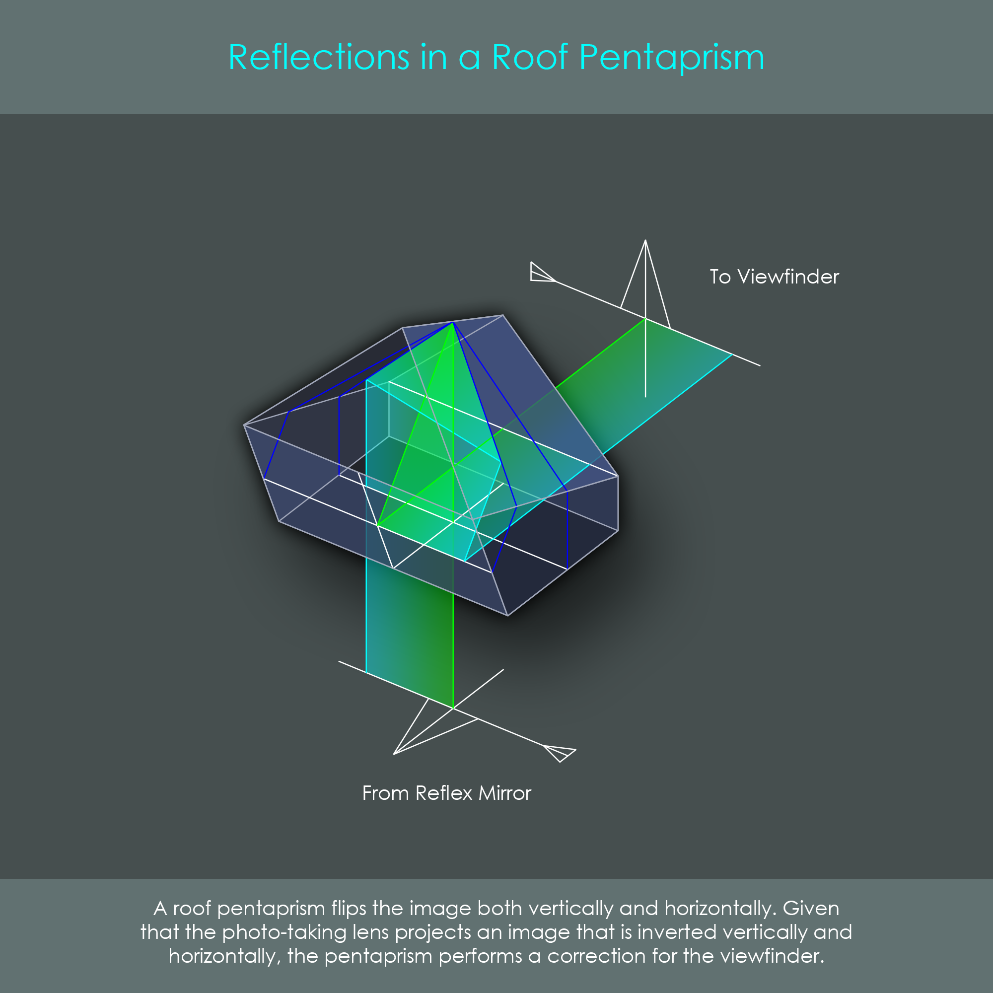
As the pentaprism in a DSLR camera faces the image that is produced on the focusing screen, there is one problem. The camera lens produces an image that is reversed in both vertical and horizontal orientation. By the reflection of the reflex mirror, this image gets re-inverted vertically, leaving an image that is still horizontally reversed. For the viewfinder to display a correctly oriented preview, the image needs to be reflected left-to-right as it is passed through the pentaprism. This horizontal inversion is done by replacing one of the reflective faces of a standard pentaprism with a section shaped like a roof. That roof is not an additional component but rather describes the shape of the cut: Two additional coated surfaces are angled towards each other in a 90-degree angle. It is the roof which horizontally reverses the image back to normal when reflecting the image. The diagram shows both features of a roof pentaprism, the deflection of the image and the correction of its orientation.
Most entry-level DSLRs are equipped with pentamirrors. These pentamirrors are not made of solid glass but a hollow case with a similar geometry than a pentaprism but with thin mirrors applied inside. The advantage of pentamirrors is that they are very lightweight and inexpensive, but they typically do not provide the same brightness of viewfinder images known by glass pentaprisms. This can be a critical factor for manual focusing under some low-light conditions. Given the fact that they consist of a hollow chamber, there is also the risk of dust and moisture entering the pentamirror if no perfect sealing is applied, degrading the mirror surfaces over time. Advanced and pro-level DSLRs typically use pentaprisms in an all-glass design with specially coated faces. They are more expensive and have a higher weight than pentamirrors, but they deliver more light to the eyepiece thanks to their more efficient reflections.
There are different viewfinder coverage ratios among DSLRs. The coverage ratio describes how much of the final image that the camera will record can also be previewed through the viewfinder. While several components within the viewfinder contribute to the coverage ratio, it is mainly the dimension of the pentaprism that really determines whether the viewfinder shows a complete preview image or not. This is because a size reduction of some pentaprism faces will result in a considerable reduction in weight, overall viewfinder size and production cost. For that reason, viewfinder coverage is also dependent on the camera model. While a Canon EOS 60D (mid-range camera) only provides a viewfinder coverage of 96%, the Canon EOS 7D (advanced-level) provides a viewfinder coverage of 100%. This means that the viewfinder of an EOS 60D does not show 4% of the preview image's edge regions while the EOS 7D provides the complete preview image. This does not sound like a real difference, but it can require post-processing if an image suddenly shows unexpected elements in the edge regions that have not been seen on-camera.
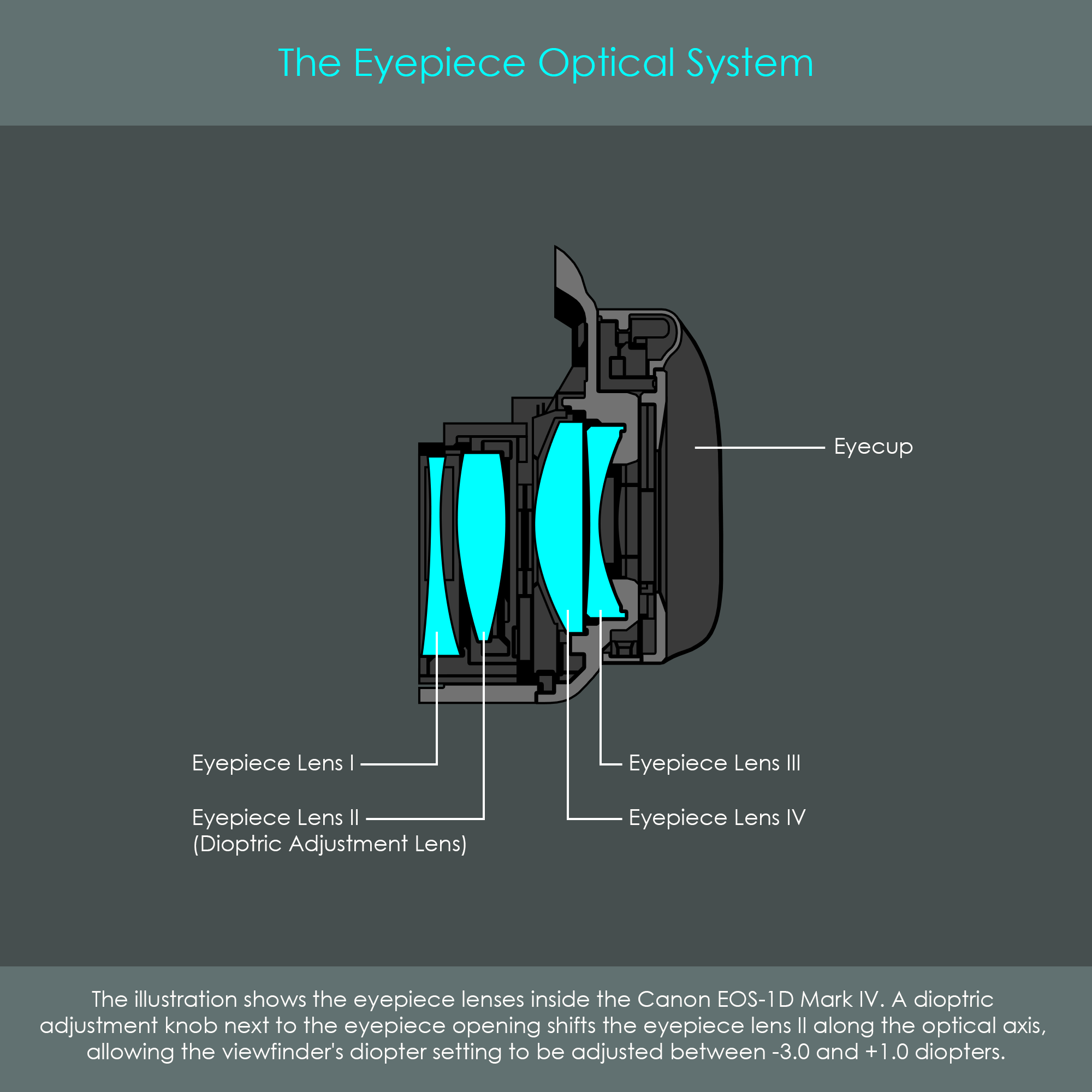
The eyepiece is what photographers use to actually inspect and assess the preview image. It is an opening at the back of the camera where light from the viewfinder optics exits the camera to enter the photographer's eye. An interchangeable eyecup made of soft rubber material is surrounding the opening, providing for a comfortable contact between the camera and the face. However, the eyepiece is more than just a simple opening on the back of the camera. In fact, it is a separate optical system hidden behind the eyecup. The exact number of eyepiece lenses varies with the camera model. In the case of the Canon EOS-1D Mark IV, there are four eyepiece lenses installed. The main functions of these lenses are as follows: