The following collection of articles provides in-depth presentations of the optical and optoelectronical functional principles of Digital Single Lens Reflex (DSLR) cameras. Understanding each component inside a DSLR and their underlying technology may help you to achieve better photographic results with your digital camera.
As per 2026, the chapters on viewfinder optics and phase detection autofocus include some of the most detailed illustrations currently available on the internet. The creation of these diagrams and illustrations required several months of research including the review of scientific publications, patent registrations, the translation of japanese websites on phase detection autofocus, contacting professionals around the globe, and the disassembly of various DSLR cameras. For this reason, the author is proud that his articles are regularly cited as a reliable source in numerous academic publications. These articles were last updated in April 2026.

The illustration below shows a cross-section through a Canon EOS-1D Mark IV, a very high-end professional DSLR camera that was introduced in 2009. At that time, the recommended retail price of the camera's body was USD 4,999. The innovation with this model was its unprecedented combination of high-speed performance, extreme low-light capability, a completely redesigned autofocus system, and high-resolution video in a rigid, durable metal body. These factors have made the Canon EOS-1D Mark IV a multimedia powerhouse for sports, news, and wildlife professionals.
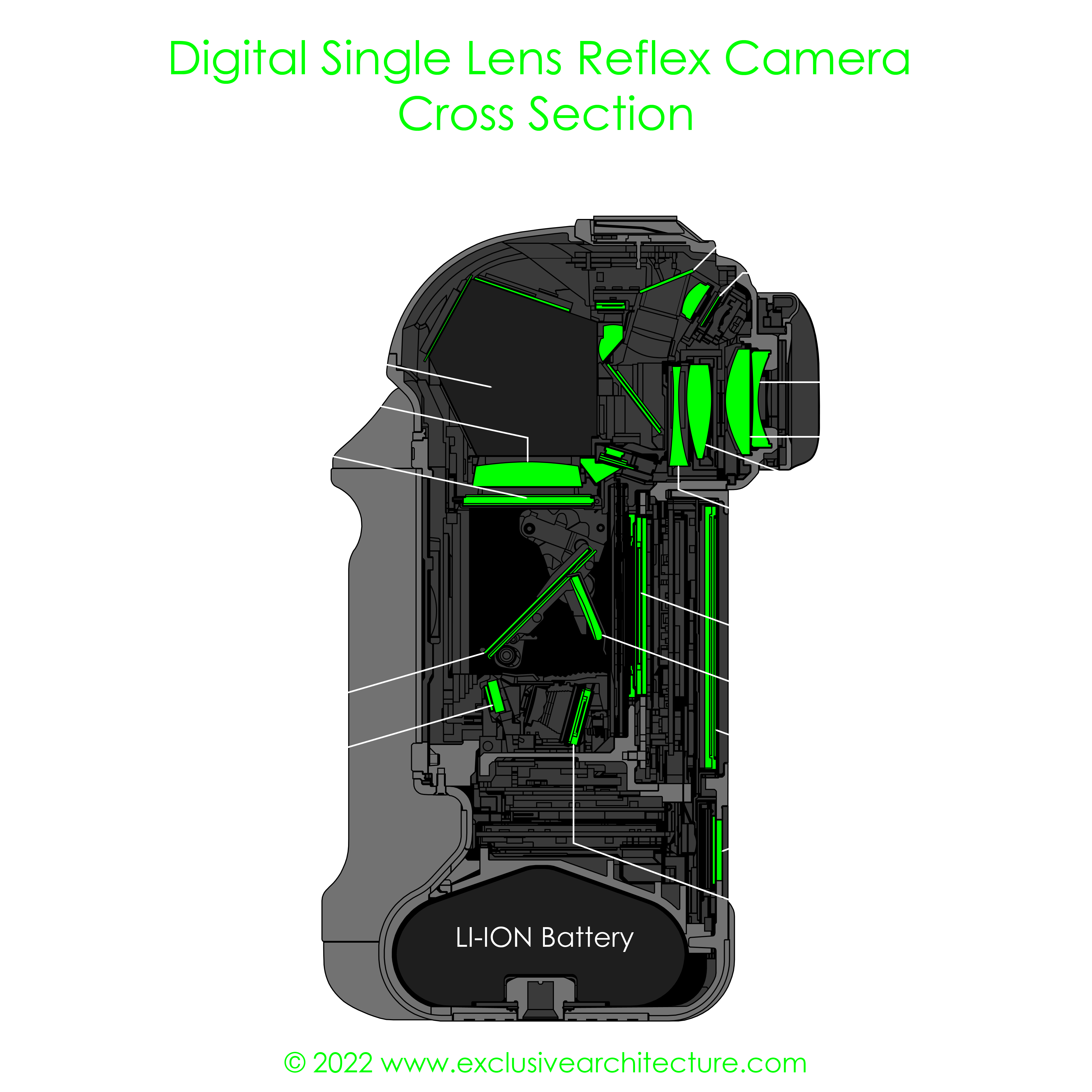
Probably the most unique component of a DSLR camera is the reflex mirror. The main purpose of the reflex mirror is to reflect the incident light towards the viewfinder optics in the upper part of the camera. In there, light hits the camera's focusing screen where it forms an image. Since the focusing screen is translucent, the image formed on the screen emits light from its top surface towards the pentaprism. A condenser lens provides uniform illumination and increases viewfinder brightness. Being deflected and corrected in rotation by the pentaprism (or pentamirror), light is redirected to the eyepiece so that the photographer can see a preview image of the photographic scene. All of this complex optical design offers two key advantages: Firstly, the viewfinder's preview image shows exactly the same focal length of the used lens and will even change in real-time once the photographer zooms the lens in or out during composition. This also ensures that the viewfinder image shows an identical perspective of the photographic scene without parallax, an apparent displacement between the viewfinder image and the final photograph. Secondly, the viewfinder of a DSLR system also takes into account filters attached to the lens. Additional information systems are built into the viewfinder such as the superimpose (SI) display as well as horizontal and vertical LCDs (only the horizontal LCD is seen on the cross-sectional view above).
One other striking feature of DSLR cameras is their extremely fast and reliable autofocus (AF). This is achieved by a dedicated autofocus sensor unit, a complex arrangement of optical elements designed to evaluate whether an image is in focus or not. This unit is typically located in the lower part of a DSLR camera, underneath the mirror. The primary mirror is not fully reflective but semi-transparent. Therefore, a certain amount of light can reach a secondary mirror, placed behind the primary reflex mirror. This secondary mirror reflects light beams towards the autofocus sensor unit where it is analyzed by highly specialized detector arrays. This is just a small glimpse of the many systems built into these high-performance cameras.
In the following chapters, you will find detailed illustrations and in-depth explanations about DSLR optics including the aforementioned viewfinder and autofocus systems, the image sensor, as well as the associated readout and processing electronics.

The image above summarizes the different paths of light while the camera is in viewfinder mode. In this state, the mirror is in its lower position and the viewfinder unit receives light from the photo-taking lens (not shown in this illustration). Note how there is another path of light passing through the main reflex mirror, and getting reflected towards the autofocus sensor by the secondary mirror.
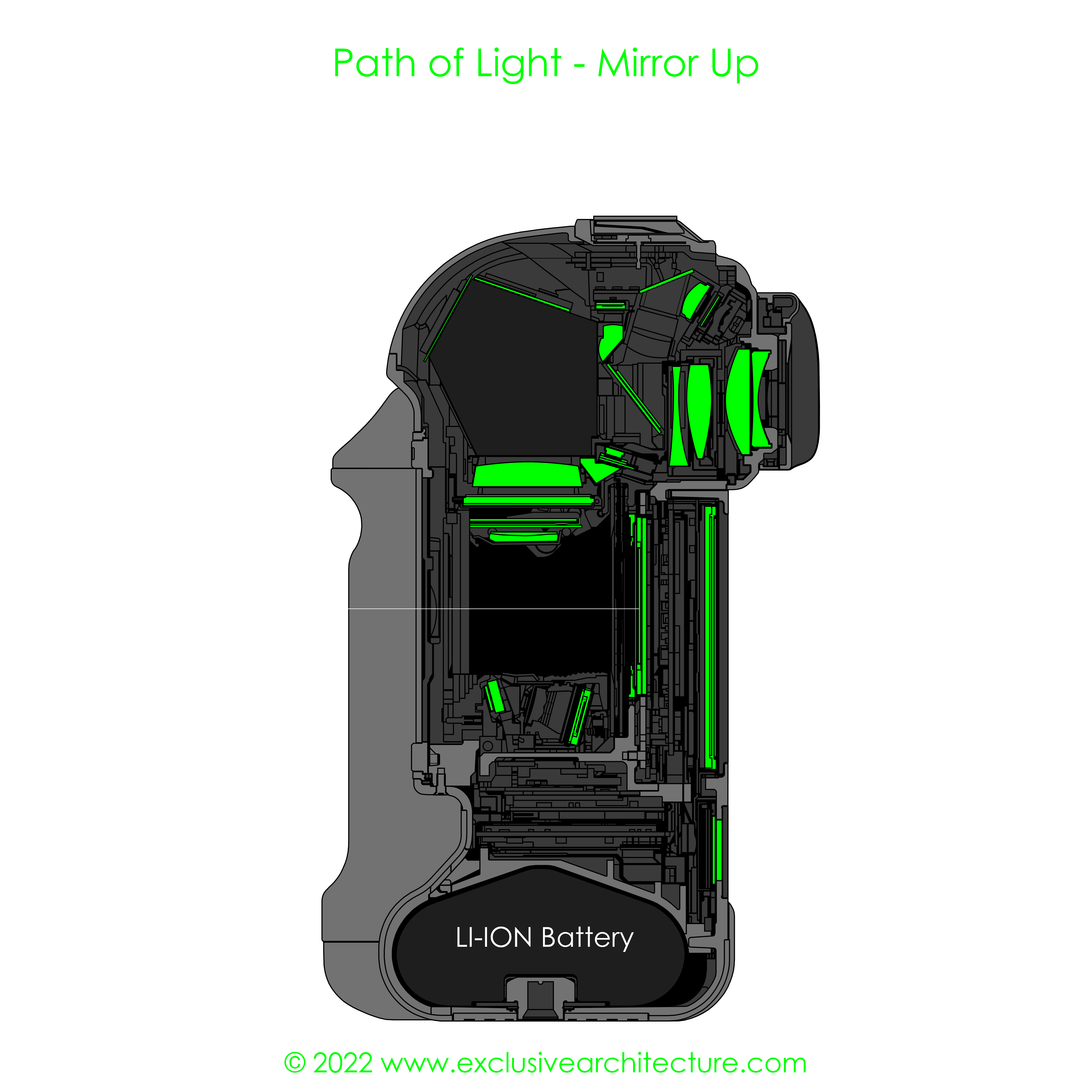
Once the shutter-release button is pressed, both the main reflex mirror and the secondary mirror flip up, exposing the rear of the morror box to light. The camera sensor is normally covered by the shutter curtains that will quickly open after the mirror has reached the upper position. With the shutter curtains opened, the sensor is finally exposed to the incident light, recording the photographic scene. After the exposure, the shutter curtain will close automatically, followed by the primary and secondary mirror folding down again. The diagram above shows the path of light while the two mirrors are flipped up.