The introduction of automatically focusing lenses has changed photography in numerous ways. Autofocus systems have significantly improved the reliability and accuracy with which fast moving objects can be shot. Round four decades ago, the new level of convenience offered by autofocus lenses has made photography more accessible to the masses. Since their first release of an autofocus lens in 1981, Canon has constantly developed their lens technology using different approaches. Over time, Canon has introduced seven different autofocus motor technologies that will be presented here.
In optics, focus describes the point at which incoming light rays converge and it is used synonymously as a concept of sharpness. Autofocus, by contrast, is a technology to automatically focus the lens at a desired subject. The autofocus detection system inside the camera determines the ideal focusing lens position and instructs the lenses autofocus drive accordingly. In 1987, Canon has introduced both the EOS camera system and EF lenses which have been designed with autofocus as standard features. There have been some Canon autofocus lenses available before that date, but these have been discontinued with the introduction of EF lenses. For this reason, this chapter concentrates on all autofocus motor types that are used in EF, EF-S, EF-M, RF, and RF-S lenses that are marketed still today.
The autofocus group of lens elements always shifts along the optical axis in a linear way. While focusing automatically, the movement is generated by some type of actuator. Autofocus actuators can basically be divided into two categories:
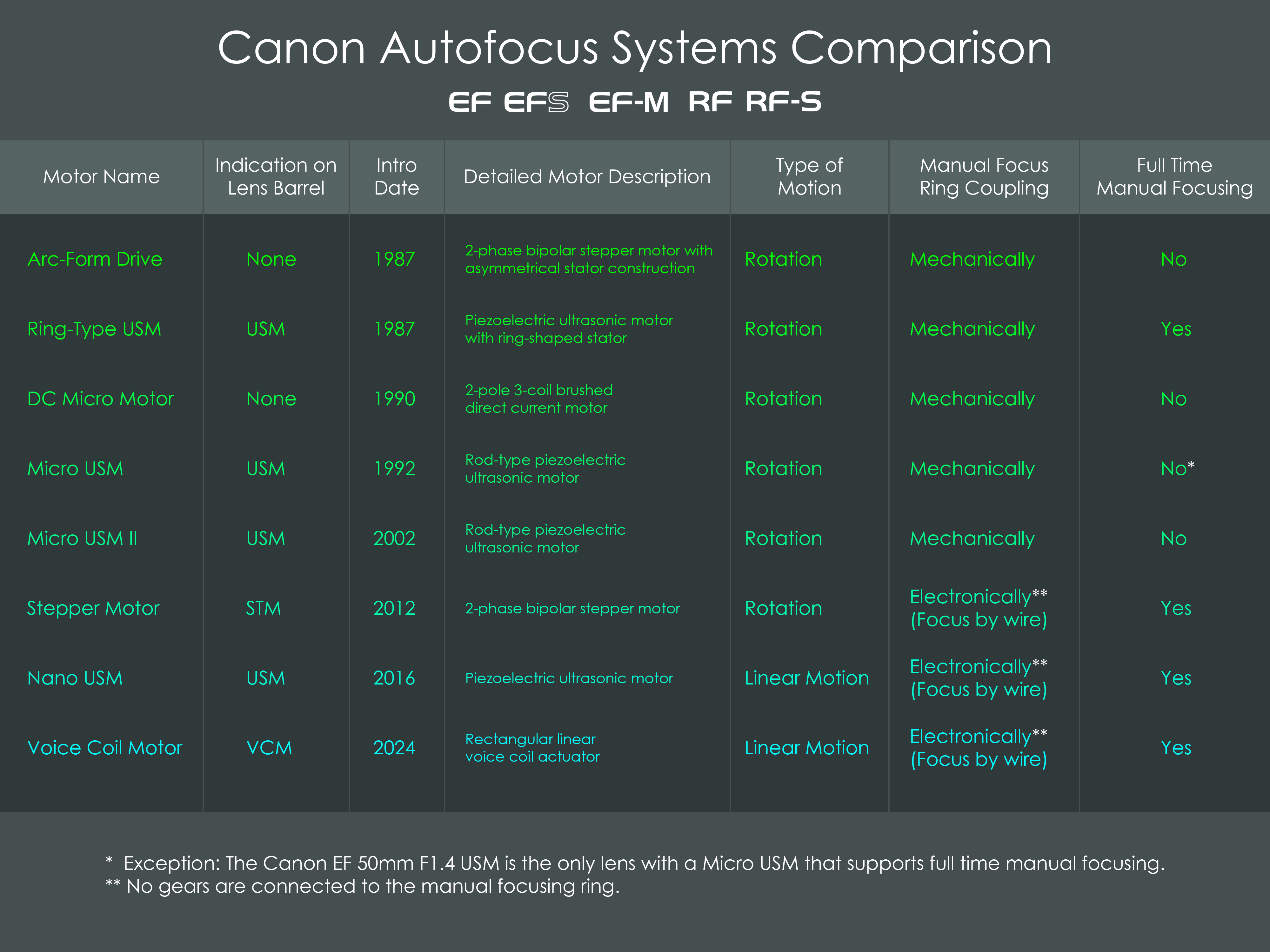
The first types of autofocus drive systems used rotary movement and these include the Arc-Form Drive, Ring-Type USM, DC Micro Motor, Micro USM, Micro USM II, and Stepper Motor. Later, the switch was made to linear drives which include the Nano USM and the Voice Coil Motor. The following comparison chart shows all of the autofocus drive types that have ever been used in Canon's EF, EF-S, EF-M, RF, and RF-S lenses.
One key differentiator between these technologies is the capability of a lens to allow full-time manual (FTM) focus override. The ring-type USM was the first autofocus system that allowed FTM focus override. Until 2012, most other lenses did not offer this type of manual focusing while autofocus is activated. The latest types of autofocus drives, including the Stepper Motor, Nano USM, and Voice Coil Motor, offer focus-by-wire. This is a concept where the manual focusing ring on the lens barrel is not mechanically coupled with the focusing group of lens elements but electronically controls the autofocus drive. Lenses that use focus-by-wire always offer full-time manual focus override.
Originally, the designation AFD stood for autofocus drive. Later, when other autofocus drive systems were introduced, the term was changed into Arc-Form Drive.
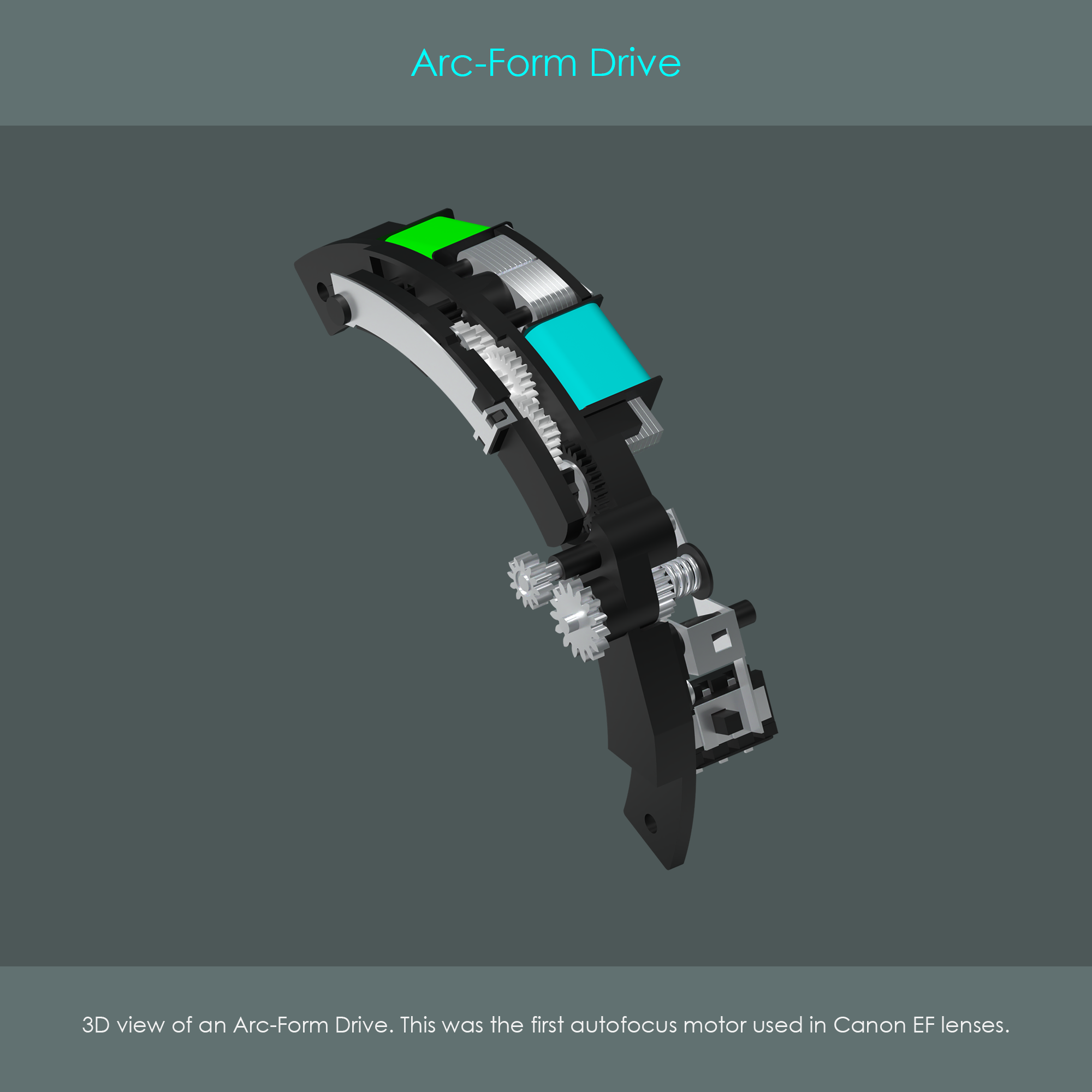
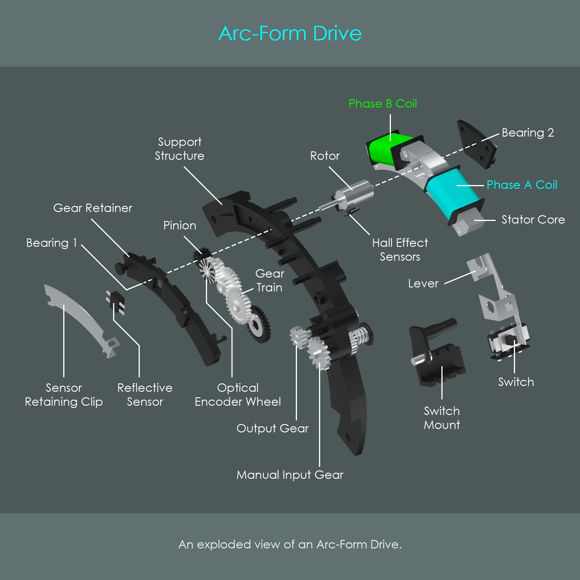
The Arc-Form Drive was the first autofocus motor that was used in EF lenses. The assembly included the motor unit, the gear drive, and a transmission that allowed the user to switch between manual focusing and autofocusing. The AFD assembly was shaped like an arc so that it could easily be installed inside a cylindrical lens barrel.
The illustration shows an Arc-Form Drive inside a Canon EF 50mm F2.5 Compact Macro lens. The unit is driven by a 2-phase bipolar asymmetric stepper motor that consists of a stator core, two electromagnetic coils (each coil is also referred to as a phase), and a permanent magnet rotor. The bipolar construction of the motor allows current to flow through each coil in both directions. The term asymmetric refers to the shape of the stator that is not rotationally symmetric as in conventional stepper motors (but it is axially symmetrical though).
The motor drives a reduction gear train that has the purpose of reducing the output gear's speed but at the same time increase the torque of that gear. A lever is used to shift the output gear in one of two possible positions where it either engages with the gear train or with the manual input gear that is connected to the manual focusing ring of the barrel.
Two feedback systems are used to monitor the drive unit during operation. One system is used to confirm proper rotation of the rotor and another system is used to measure the number of turns the unit has performed:
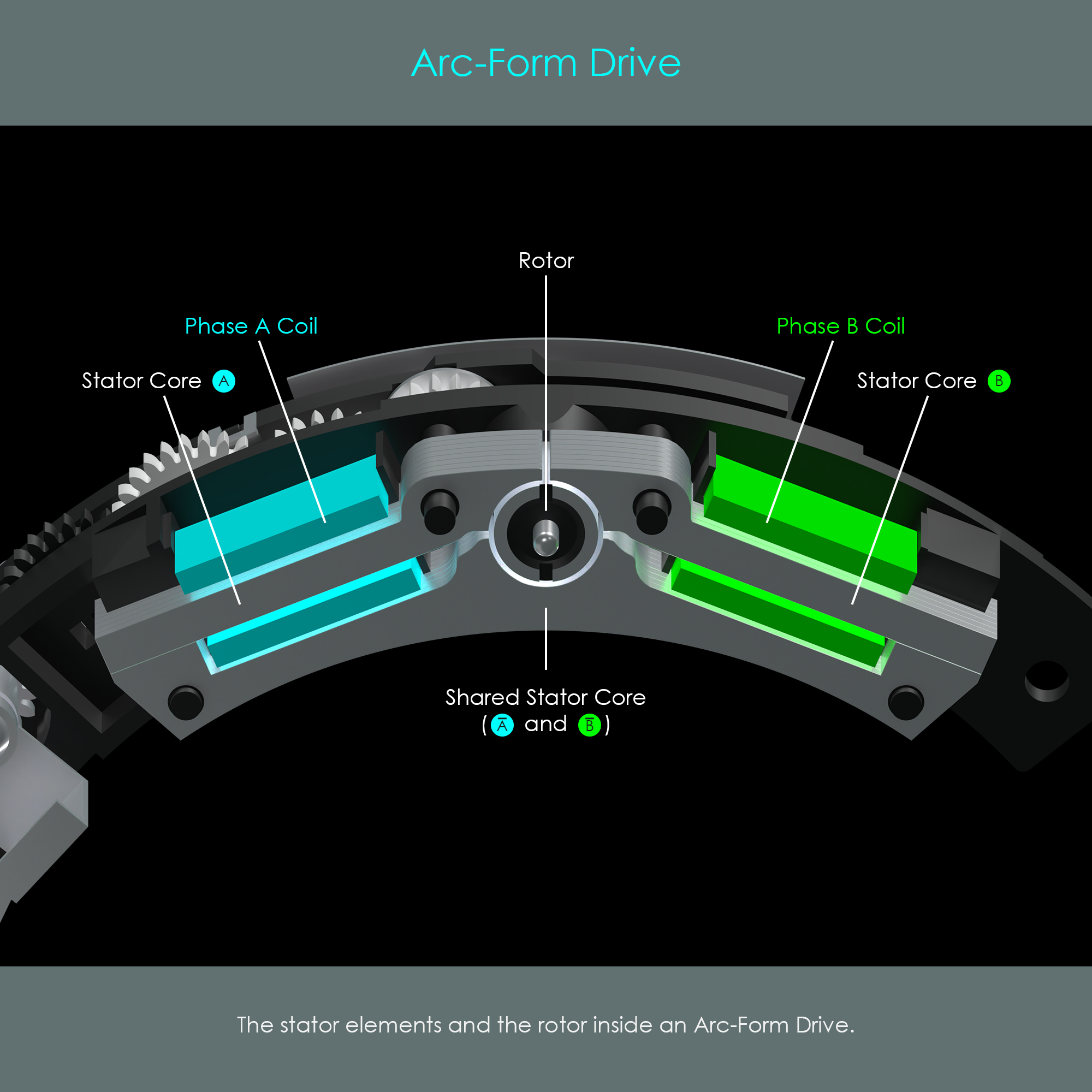
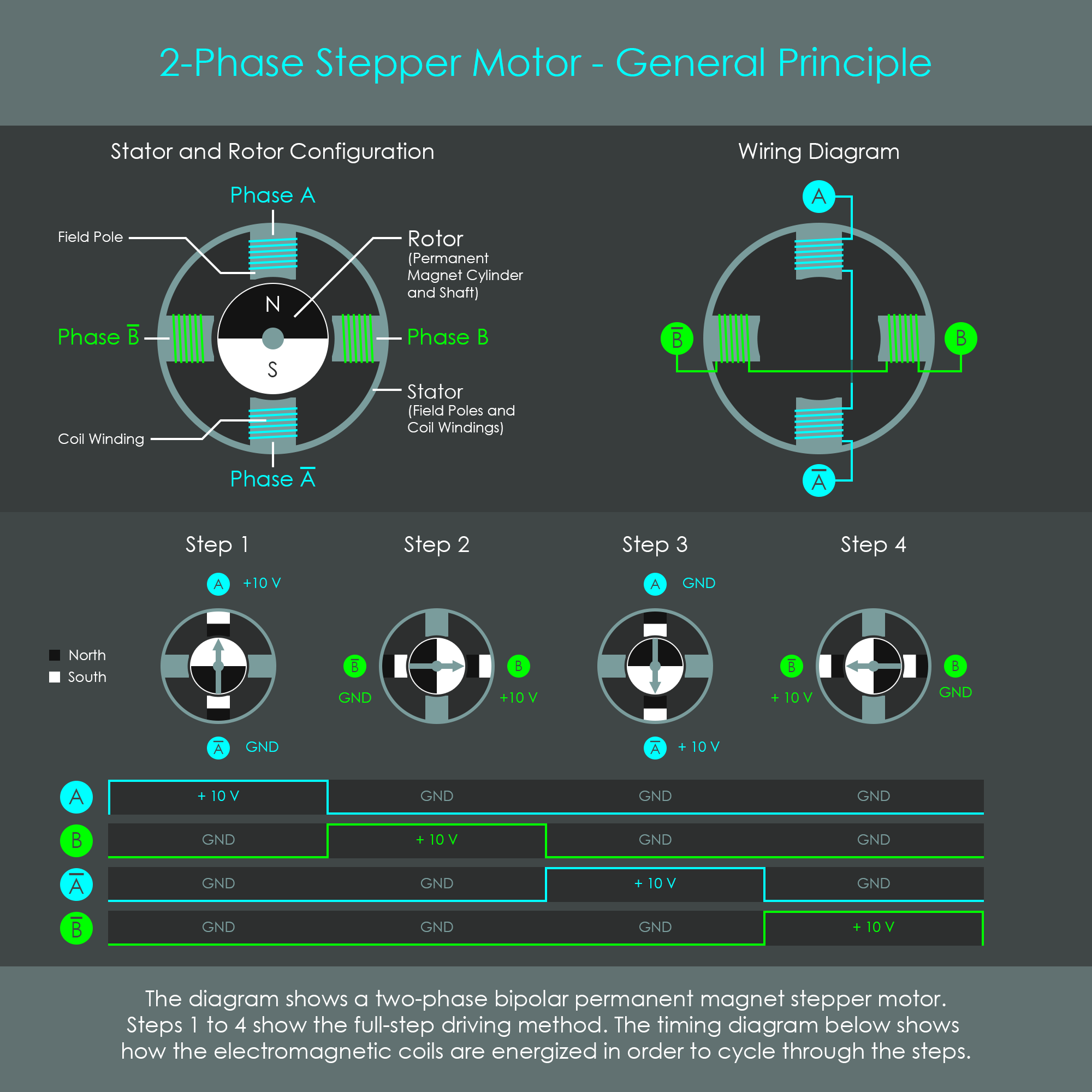
The illustration is a front view of the stepper motor with the cover removed. The rotor has two magnetic polarities opposite to each other, north and south. The stator consists of two phases that are colored in cyan and green for reasons of better explainability. The stator cores run through the phase coils to conduct the electromagnetic flux towards the rotor.
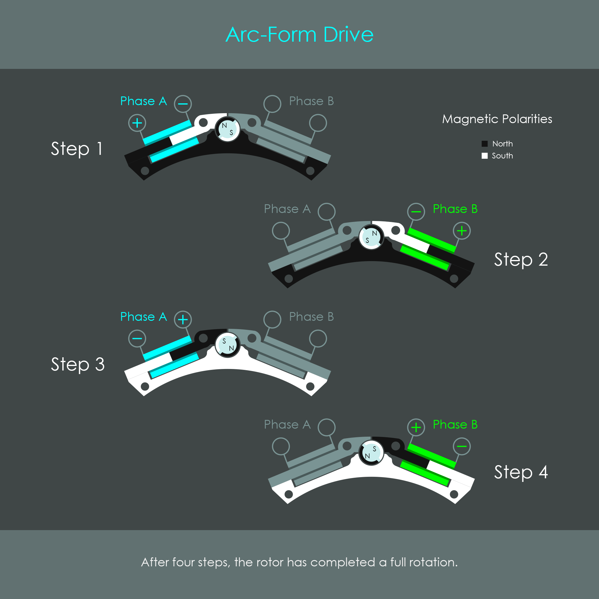
During autofocus operation, the wire coils are excited via electrical impulses, which in turn magnetizes the stator core. The polarity of the voltage applied to the two coils is changed in a pre-defined sequence. The rotor performs a complete rotation in four steps:
The sequence of steps is repeated as long as the rotor is required to turn. If the sequence is run in reverse from step 4 to step 1, the rotor turns counter-clockwise. The diagram summarizes these four steps.
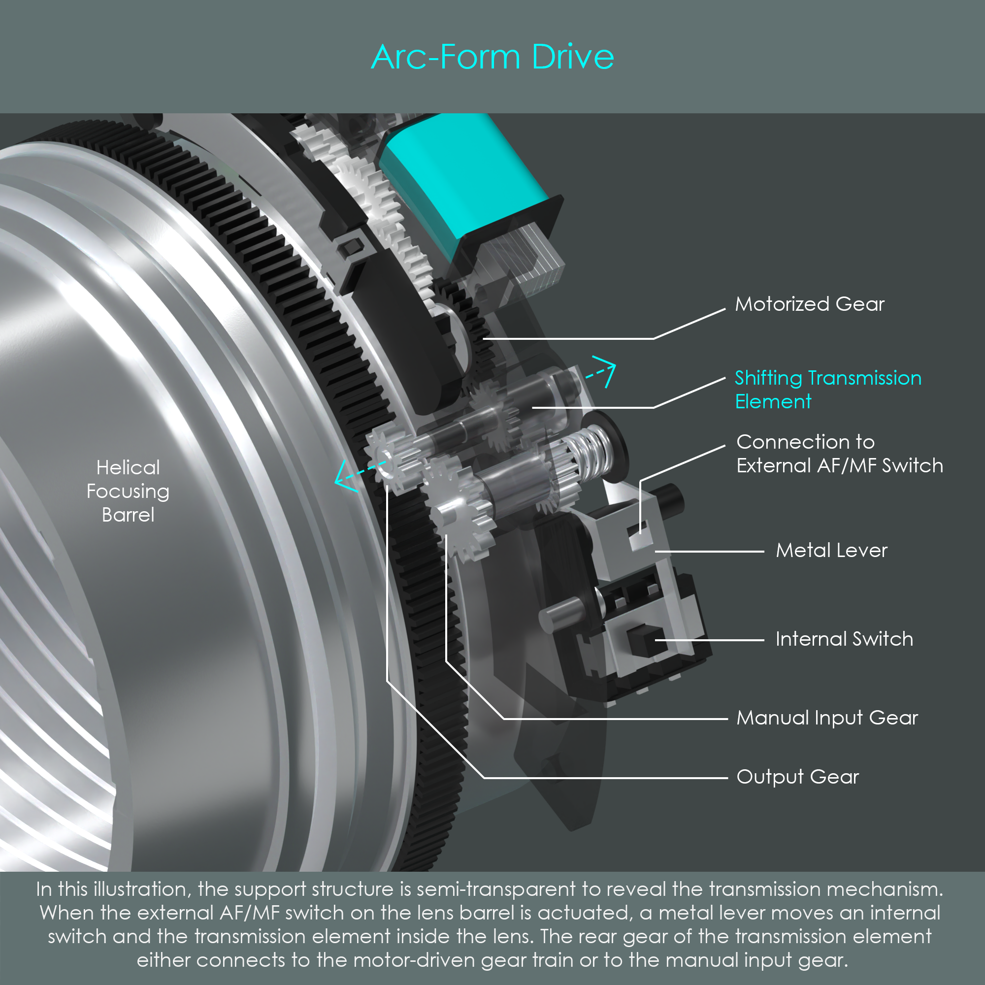
The AFD motor was designed with a transmission element that is also the output gear, the one that actually drives the helical focusing barrel. Note how the focusing barrel has a wide gear rim along its perimeter that allows the transmission element to shift a certain amount while always remaining engaged with the focusing barrel. The metal lever is connected to the MF/AF switch on the lens barrel and it shifts the transmission element so that it connects the output gear either with the motorized gear train or with the manual input gear. If the output gear is connected to one option, it is disengaged from the other option. For that reason, the Arc-Form Drive does not have full-time manual focus override available.
In terms of overall performance and usability, the Arc-Form Drive is considered to be noisy during operation and slower than other autofocus drives. When following moving subjects, the system shows a noticeable reaction time. Lenses with an Arc-Form Drive have to sequentially focus and then stop down the aperture diaphragm. All other lenses with different autofocus motors are able to operate the autofocus motor and aperture diaphragm at the same time. Despite these weaknesses, AFD lenses still offer reliable autofocusing performance.
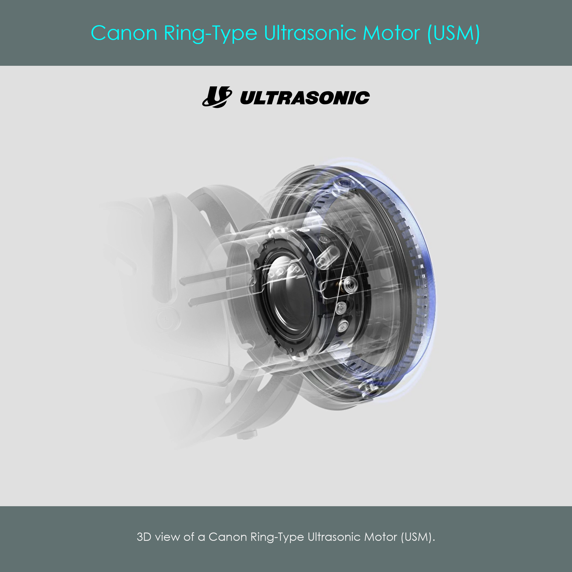
Canon's ultrasonic motors are very exceptional types of actuators. They neither have electromagnetic coils or magnetic rotors, so their motion is not generated by magnetism like in traditional motors. Instead, they use an ingenious combination of piezoelectric effects and friction. Introduced in November 1987 with the Canon EF 300mm F2.8L USM lens, the ring-type USM was the first implementation of this piezoelectric technology in photographic lenses, and in the years that followed, some different types of USM drives would appear.
Canon's ring-type ultrasonic motor – as the name suggests – is shaped like a ring and, for that reason, fits perfectly inside the lens barrel. The optical system of the lens runs through the opening of that construction. At the time of its advent, this new technology was groundbreaking in its design and functionality, being ultra-fast and silent. They provide a high level of torque powerful enough to move even heavy groups of focusing lens elements inside super-telephoto lenses. Due to their high torque, no speed-reducing gear train is required when connecting the motor to the focusing mechanism. The ring-type USM has high holding torque maintained at zero input power and offers low inertia from its rotor providing rapid start and stop characteristics. In addition, this type of drive technology is unaffected by electromagnetic fields.

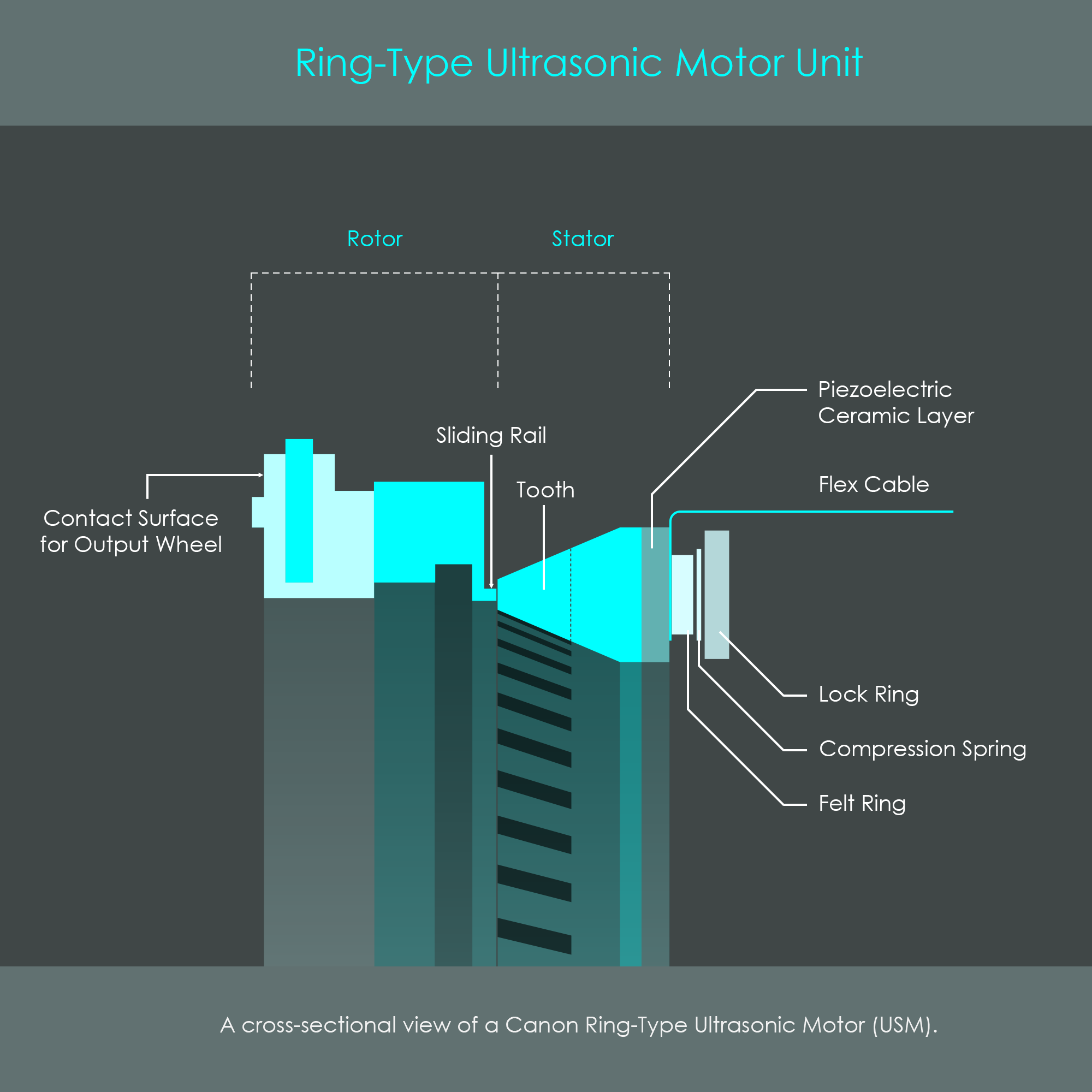
The ring-type USM can be divided into the rotor, the piezoelectric stator, and various support rings.
The following illustration is a cross-sectional view of the ring-type USM when it is fully assembled. The piezoelectric layer is what generates vibrations. A flex cable connects the piezoelectric elements with the lens circuit board, and therefore provides power to this element. Once the unit is installed inside a lens barrel, a dedicated contact surface on the rotor pushes against wheels on an output ring (not shown in this illustration) that ultimately drives the focusing mechanism.
The compression spring creates a tension that is also referred to as preload force. Flat surface finishes of the sliding rail and the stator teeth ensure a good friction coefficient between rotor and stator. The preload force and the friction between the rotor and the stator determine the passive holding torque of the motor at zero power input.
Canon uses stator rings of two different sizes. The medium sized stator has an outer diameter of 62 mm, and the larger sized stator has an outer diameter of 77 mm. There is a huge number of Canon lenses that use ring-type ultrasonic motors as their autofocus drives. The following list is only a very short excerpt:
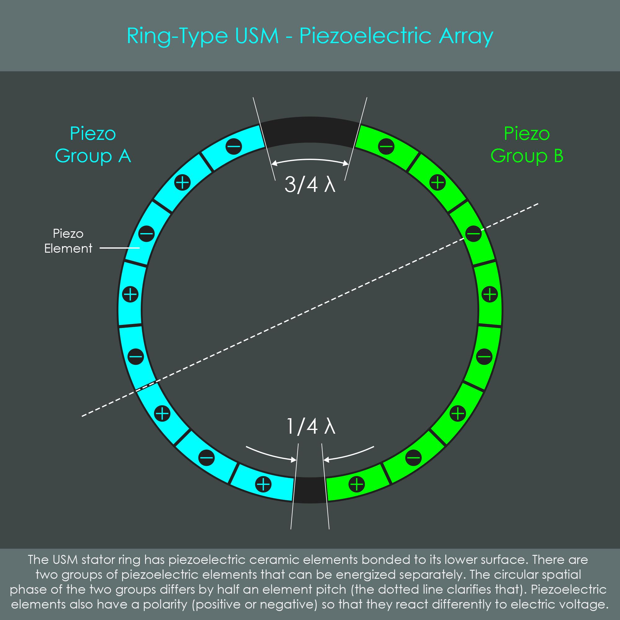
The operation of the motor requires the stator to vibrate in a very precise way. This vibration is generated by a segmented piezoelectric ceramic ring that is welded to the back of the elastic stator body. The illustration of the piezoelectric array shows the distribution and configuration of piezo elements on the ring.
The individual piezo elements are grouped together into groups A and B. Each group can be energized individually, and set the ring into vibration to form a standing wave with wavelength λ. Two piezo elements cover one full wavelength λ, and therefore each single piezo element has a length of λ/2. One of the key factors to ensure proper wave excitation in the stator is that both piezo groups are offset by λ/4 as shown in the illustration. This is also referred to as a spatial phase shift of λ/4.
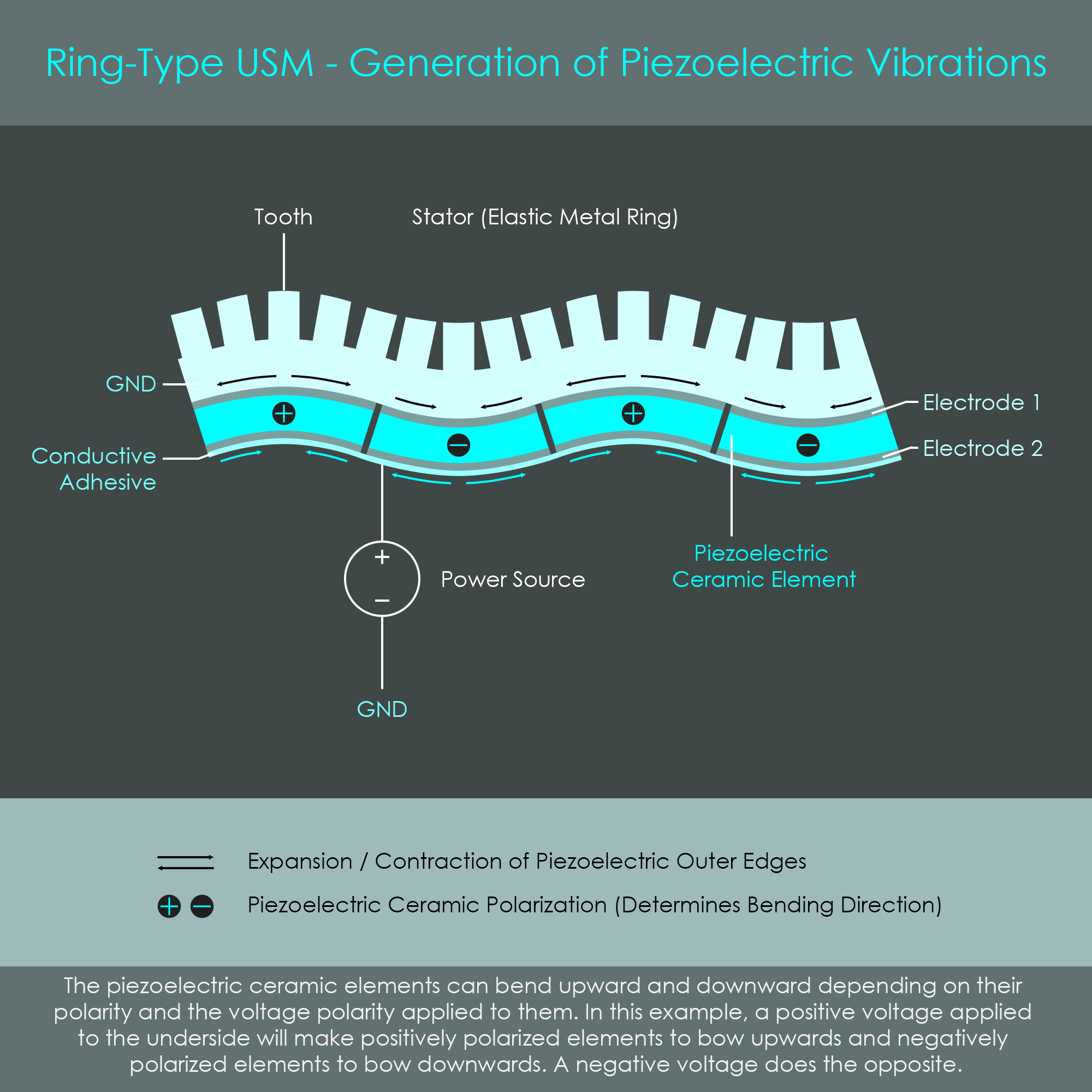
Piezoelectric ceramic elements are sandwiched between two electrodes. Electrode 1 is in direct contact with the metal stator ring and serves as ground (GND). In the following illustration, the lower electrodes of all piezo elements are covered by a layer of silver conductive adhesive so these elements are electrically connected to one group.
The piezoelectric ceramic elements have the property to deform when an electrical field is applied, an effect also described as the inverse piezoelectric effect. The direction in which piezo elements deform is defined by their piezoelectric polarization, expressed via positive and negative signs in this slightly simplified diagram. Depending on the polarity of the voltage applied across the electrodes, the individual piezo elements bend upwards or downwards. As piezo elements are arranged with alternating piezoelectric polarities, energizing the piezoceramic layer shapes the stator into a waveform. When the electrodes are subject to an alternating voltage of high frequency, the stator ring begins to oscillate. The amplitude of these oscillations is as small as 1-2 µm.
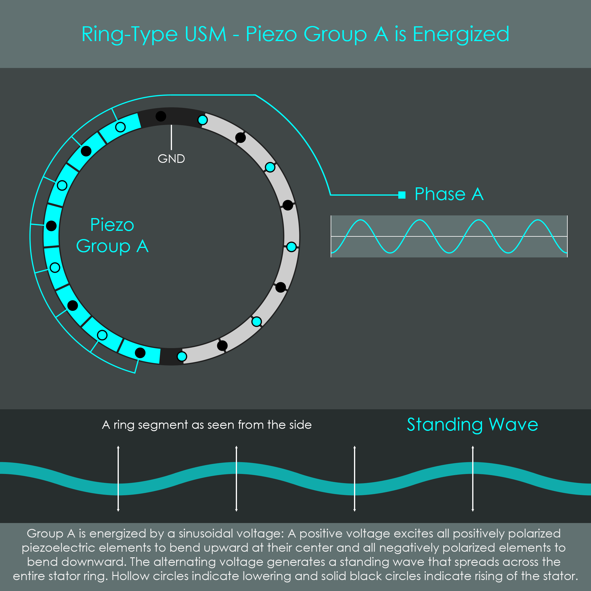
For the sake of better understanding, the two piezoelectric groups are viewed from the top, and energized separately. Piezo group A is fed by a distinct sinusoidal voltage (phase A) while piezo group B remains de-energized. This not only generates a standing wave across group A but the wave unfolds across the entire stator ring. Looking at a snapshot in time, hollow circles indicate valleys in the stator, whereas solid black circles indicate peaks in the stator. Note how the peaks and valleys are exactly at the center of each piezo element of group A, whereas on the opposite side of the ring, peaks and valleys are exactly between the piezo elements. Over the course of one sine oscillation, peaks will turn into valleys and back into peaks. At the same time valleys turn into peaks and back into valleys. A clear standing wave is formed only if the excitation frequency is equal to the natural flexural vibration resonant frequency of the stator. The resonant frequency of Canon's ring-type USM is approximately 27,000 Hz (oscillations per second). This frequency is in the ultrasonic range, which is why this type of autofocus technology is called ultrasonic. Enlarging the illustration shows an animation of phase A generating a standing wave.
Now piezo group B is fed by a distinct sinusoidal voltage (phase B) while piezo group A remains de-energized. Again, a standing wave is generated and unfolds across the entire stator ring. This time, peaks (hollow circles) and valleys (solid black circles) are at the center of each piezo element of group B, whereas on the opposite side of the ring, peaks and valleys are exactly between the piezo elements. This shows that the two standing waves generated by group A and B are not congruent. Enlarging the illustration shows an animation of phase B generating a standing wave.

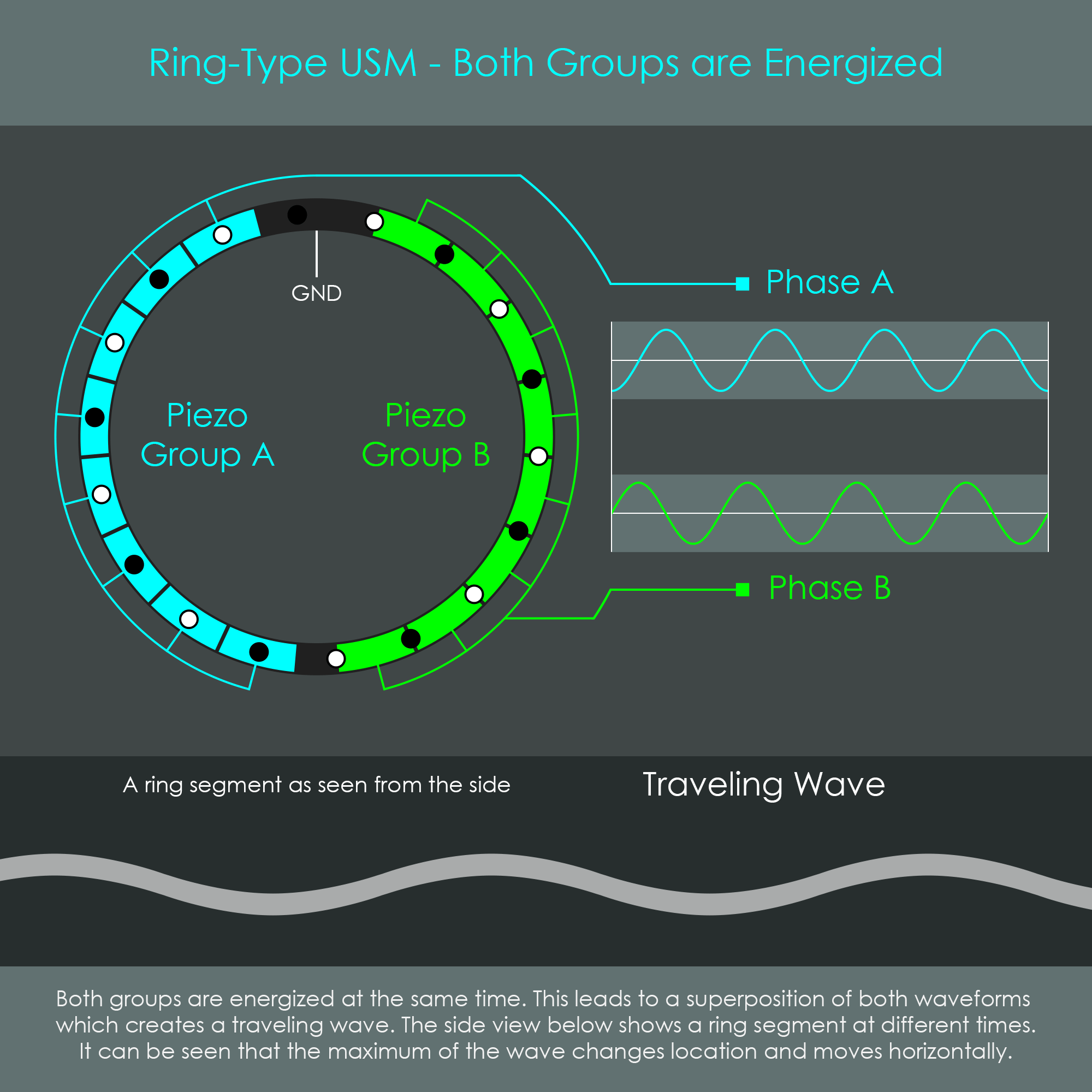
When both piezo groups are energized at the same time, their vibration-induced standing waves are combined and form a new wave. When phase A and phase B are shifted by a quarter of a sine wavelength λ – called a temporal phase shift of λ/4 – the resulting wavelength is a traveling wave. This temporal phase shift can be achieved, for example, by using a sine wave for phase A and a cosine wave for phase B. Unlike a standing wave, the peaks and valleys of a traveling wave move around the circumference of the stator ring similar to waves on the surface of water. This traveling wave is the source of the motor’s rotational energy. Enlarging the illustration shows an animation of both phases generating a traveling wave.
The sign of the temporal phase shift determines the propagating direction of the traveling wave, and consequently also the rotating direction of the rotor. The stator has teeth cut into the material, and these are designed to amplify the movement of the ring.
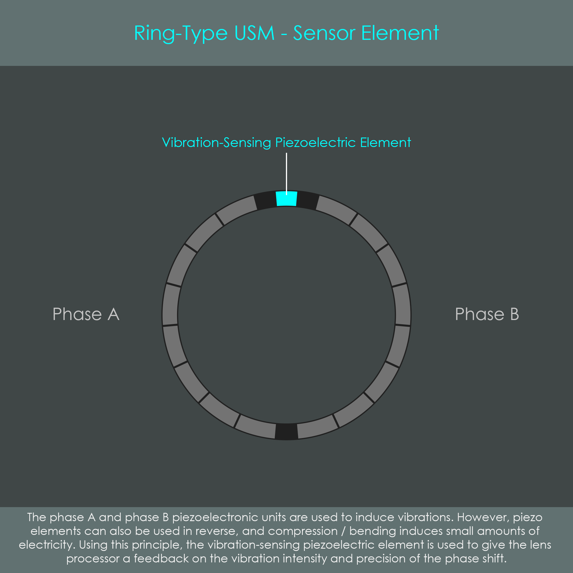
Not all piezo elements on the stator ring are used to generate waves. One small piezo element is located between the wave-generating piezo groups A and B and it serves as a sensor to measure the intensity of stator oscillations. Like all other piezo elements, the sensor element is sandwiched between two electrodes 1 and 2 (not shown in the illustration). Electrode 1 is directly connected to the metal stator body and serves as ground, whereas electrode 2 is on the opposite side and connects to the sensor line.
It was described earlier that applying a voltage to a piezo element generates a deformation of that element, referred to as the inverse piezoelectric effect. The actual (non-inverted) piezoelectric effect, however, is that pressure or deformation (such as bending) of the piezo element will generate an electric voltage. Consequently, the piezo's electrical output reflects the wave amplitude of the stator at its location. This signal is picked up by the control circuitry and can be used to adjust the frequencies of phases A and B accordingly.
This feedback control system is required to monitor the proper excitation of the stator ring, and to achieve maximum amplitude of the traveling wave. The maximum amplitude can only be attained when the wave-generating phases precisely hit the natural resonance frequency of the stator body. That natural resonance frequency may vary from unit to unit due to small production related variations in dimensions, and for a given unit the natural resonance will vary with the temperature of the stator.
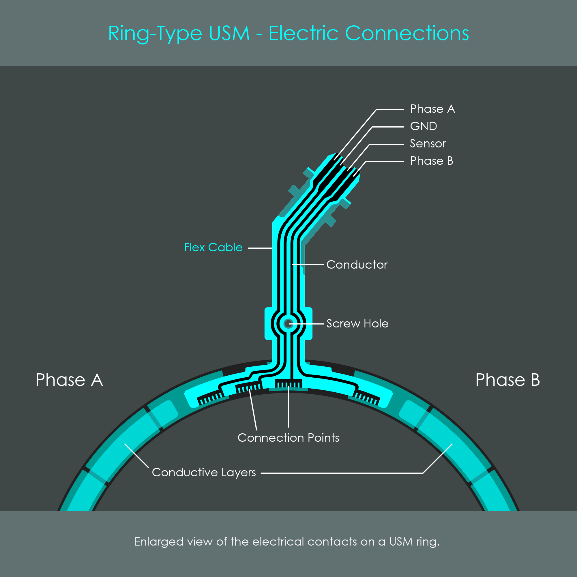
The illustration of the stator ring's electric connections shows a piece of flex cable (copper wire traces laminated onto a thin film) attached to the back of the stator ring. All piezo elements – both wave generating elements and the sensor element – have electrodes that are in direct contact with the conductive stator ring. The GND wire is directly connected to the metal stator body, and therefore all piezo elements share the metal body as a common ground connection. The phase A wire is connected to the exposed electrode of the first piezo element of group A, and a thin film of silver conductive adhesive electrically connects all other elements of phase A with the first element. The phase B wire is connected to phase B in a similar way. The sensor wire is connected to the exposed electrode of the sensor element.
The following illustration shows 3D models of the ring-type USM stator. On the inactive stator ring, all teeth are in the same plane, allowing the stator to rest flat on the rotor. In this flat condition, the focusing lens group is automatically held in place due to the strong friction (similar to a disc brake). Once the stator is excited, it forms a traveling wave, here greatly exaggerated for the sake of clarification. The number of waves per cycle depends on the configuration of piezo elements. In this example, there are nine waves per cycle, but Canon also uses stators that form seven waves. The number n of waves formed on the stator means that one particular wave peak requires n excitation periods to completely travel around the stator one time.
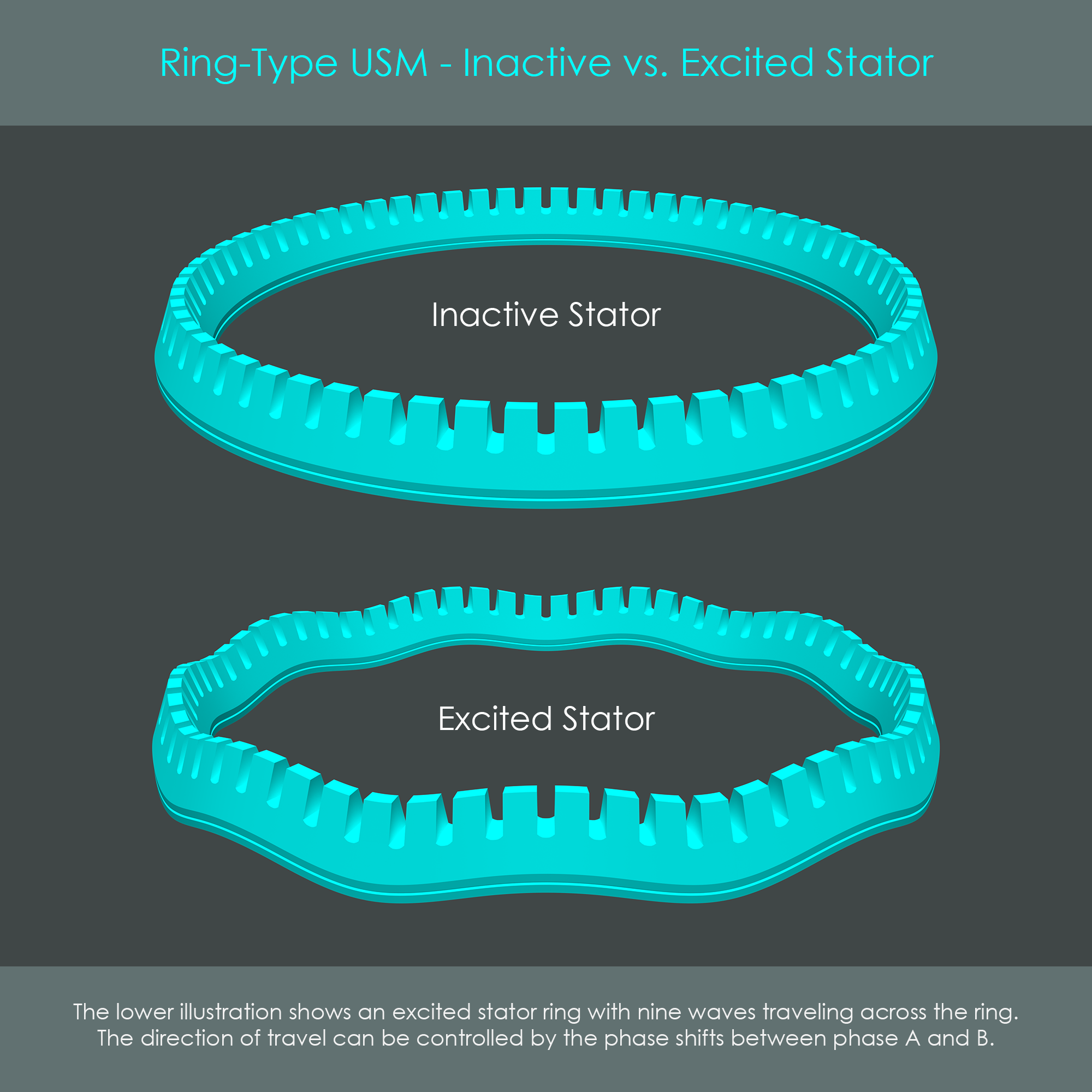

The animation shows nine waves traveling across the stator ring in a very slowed-down form. It is clearly visible that the stator itself does not turn around its axis but only the peaks and valleys move as it performs this undulating vibration.
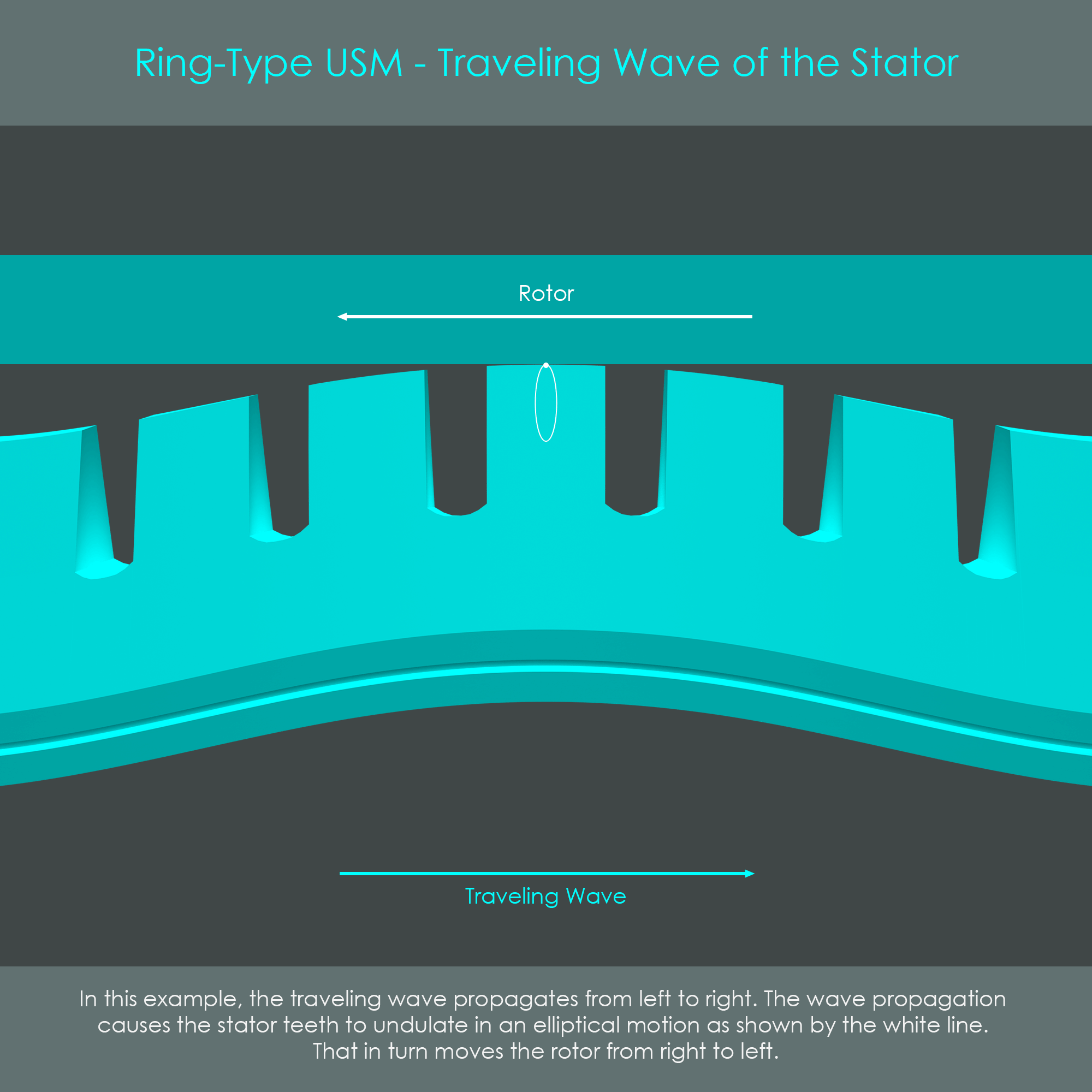
The generation of a traveling wave can be considered as the first step in a two-step energy conversion process. The second step is the stator teeth transmitting their vibrational energy into a unidirectional continuous movement of the rotor via friction. Looking very closely at the stator teeth, the traveling wave induces elliptical motions at the tips of each tooth. In the animation, only one elliptical path of one tooth is shown, but all the other teeth carry out identical elliptical motions. Where the traveling wave forms peaks, the teeth are pressed against the rotor and push it in the direction of the elliptical motion. As a result, the rotor moves in the opposite direction of the traveling wave.
It can be calculated how fast the traveling wave propagates. It is assumed in this example that 27,000 Hz is exactly the natural resonance frequency of the stator ring. With nine peaks formed across the stator, it requires nine excitation periods for one peak to completely run around the stator ring one time. Thus, if the excitation frequency is at 27,000 Hz, one peak will travel a full revolution around the stator ring 3,000 times per second. Although the peaks travel at an extremely fast speed, the speed of the rotor is comparatively low. The rotor typically turns at a rate of 70-90 revolutions per minute, if excited continuously. The speed can be lowered by exciting the stator via pulse-width modulation. The microscopic oscillations of the tooth tips are the reason why the ratio between rotor speed and traveling wave speed is very low. This low ratio is actually an advantage as no speed-reducing gearbox is required, and the rotor can be directly coupled to the focusing mechanism of the lens barrel.
The ring-type ultrasonic motor operates a two-stage energy conversion process: In a first stage, electrical energy is converted into an undulating motion by the piezoelectric elements of the stator. In a second stage, these ultrasonic vibrations at around 27 kHz are converted into a continuous unidirectional rotating movement of the rotor by friction on the stator.
The traveling wave is generated by two main factors: Two groups of piezoceramic elements must be arranged with a spatial phase shift of λ/4, and these two groups must be energized with a temporal phase shift of λ/4. The elliptical motion of the stator teeth is transferred into the rotor due to friction between the stator and rotor, caused by the pressure contact (preload force) between stator and rotor. Friction between stator and rotor.
Although being extremely well suited for photographic camera lenses, these motors show some drawbacks:
It was described in the beginning of this chapter that the ring-type ultrasonic motor was the first autofocus system that allowed full-time manual focus override. This is not a function of the ultrasonic drive unit itself, but rather of the cleverly designed differential mechanism.
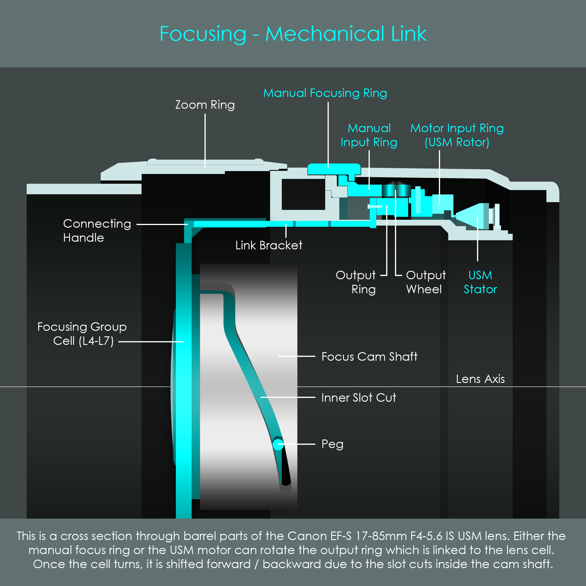
The challenge with the implementation of full-time manual focusing in general is that the user must be able to manually override the autofocus system (by turning the focusing ring on the barrel) without forcing the motor or grinding the gears. The ring-type USM prevents this from happening via an additional output ring that connects to the focusing group of lenses via a link bracket. Once this output wheel is turned, the focusing group adjusts the focusing distance of the lens. They key feature of this output ring is that it has three small wheels installed along its outer periphery. These wheels are sandwiched between the two input options – the manual input ring and the motor input ring (the USM stator). This is a rotary differential mechanism, and it allows either one of these input options to turn the output ring without exerting a force on the other input option. For that reason, the manual focusing ring can be turned without forcing the rotor into any direction. Due to this rotary differential, full-time manual focusing has become a standard feature on all lenses with a ring-type ultrasonic motor.
The following illustration shows the output wheel with its small carrier wheels. The top right shows a schematic of both input options (manual input and motor input) and how they are arranged in the lens barrel. Note that due to the differential construction the output wheel does not turn at the same speed as the input wheels, but at a speed defined by the formula: vOUT = vIN1 + vIN2⁄2 where vIN1 refers to the speed of the manual input ring and vIN2 refers to the speed of the motor input ring. If one of the input rings is not moving (which is normally the case), the output speed vOUT is half of the input speed.
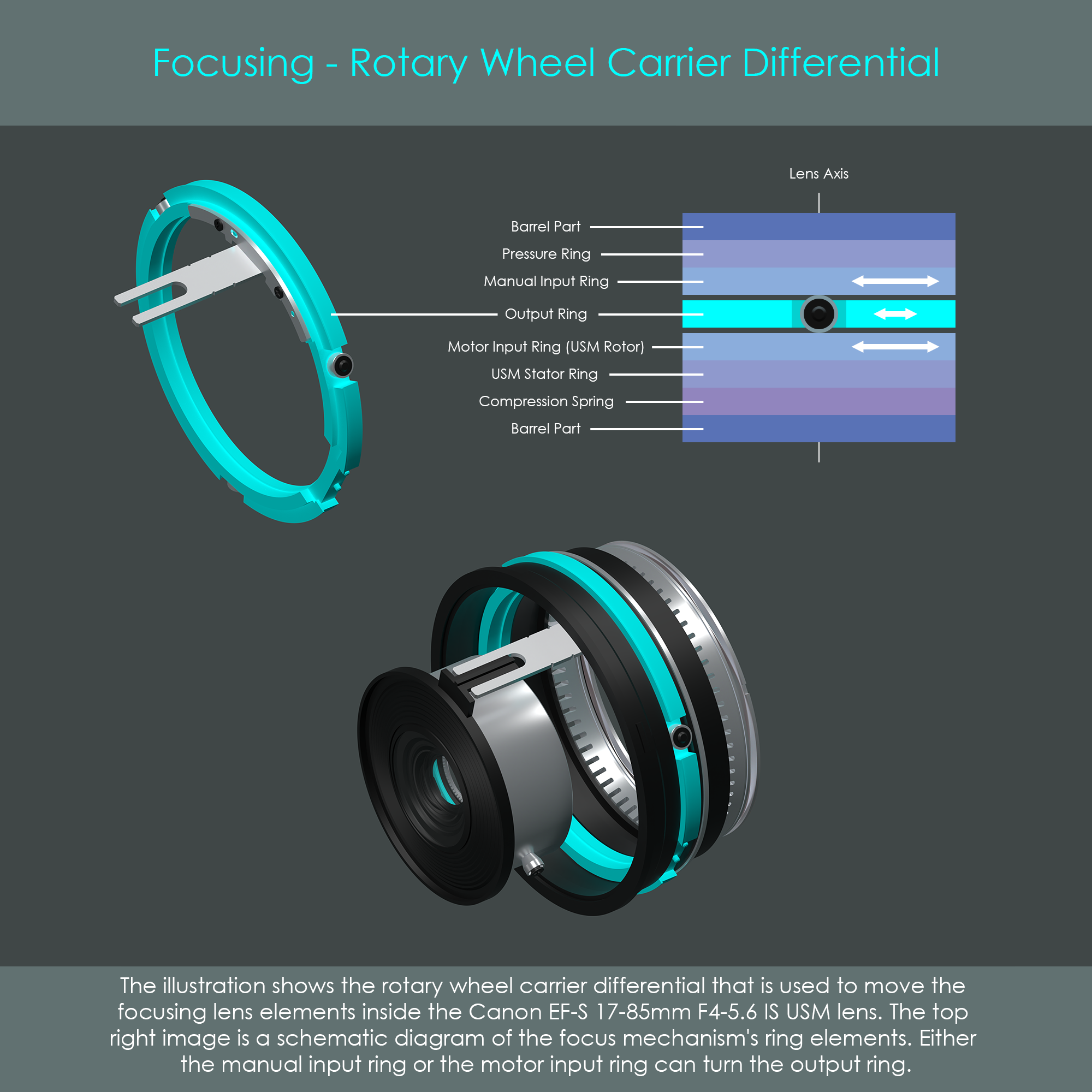
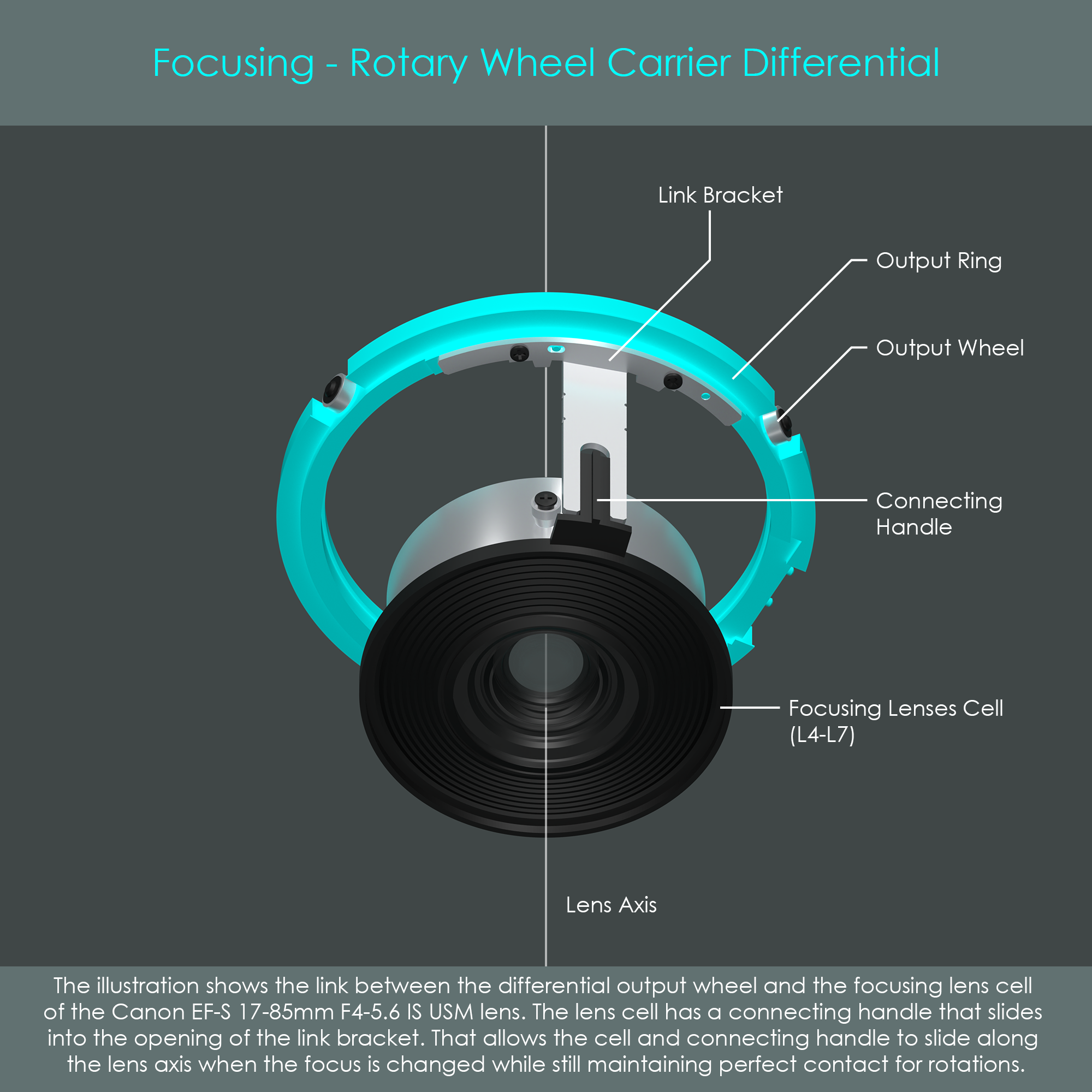
This diagram is a front view of the rotary differential mechanism. It is clearly visible how the mechanical link is established between the output ring and the focusing lens cell. As the differential mechanism turns around the lens axis, the focusing lens cell is shifted forward or backward, while still remaining engaged with the link bracket via the connecting handle. To ensure smooth movements, Canon uses some lubrification on the sliding elements.
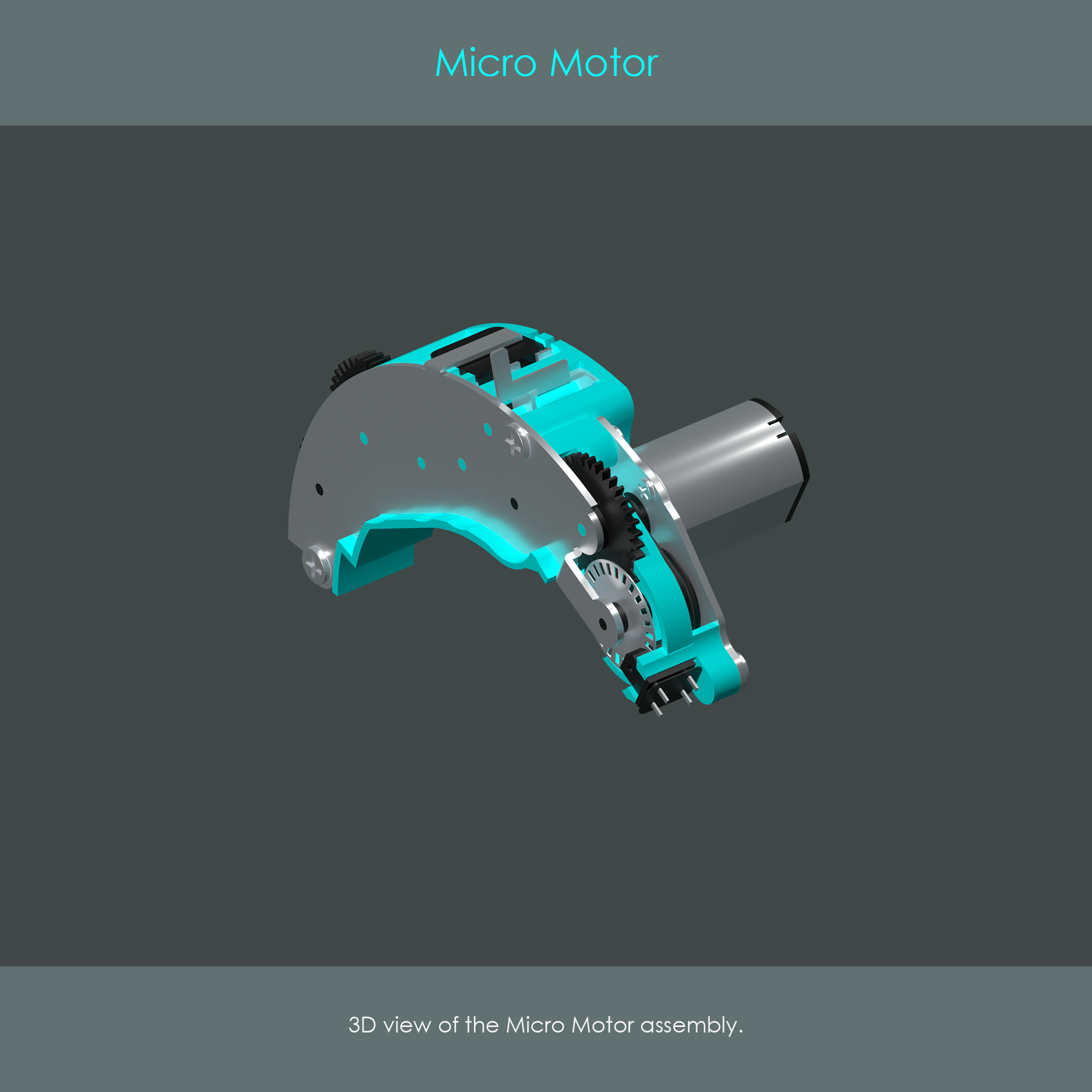
The DC Micro Motor – sometimes abbreviated MM – looks quite similar to the AFD motor. It has almost an identical shape. In addition, the DC Micro Motor also uses a reduction gear train to transmit the motor's power to the focusing lens barrel. However, the type of motor itself is different. Instead of a stepper motor as used in the AFD, this type of autofocus drive uses an ultra-compact direct current (DC) motor. This is an extremely common type of motor, and it is considered to be the least advanced autofocus motor used in Canon lenses along with the AFD. Canon primarily uses the DC Micro Motor in entry-level autofocus lenses. Here are some examples of lenses that use this type of drive system:
Once power is supplied to a direct current motor, the rotor starts to turn very fast. For that reason, the gear train attached to the motor uses a high reduction ratio to lower the speed of rotation. At the same time, rotational torque is increased towards the output gear.
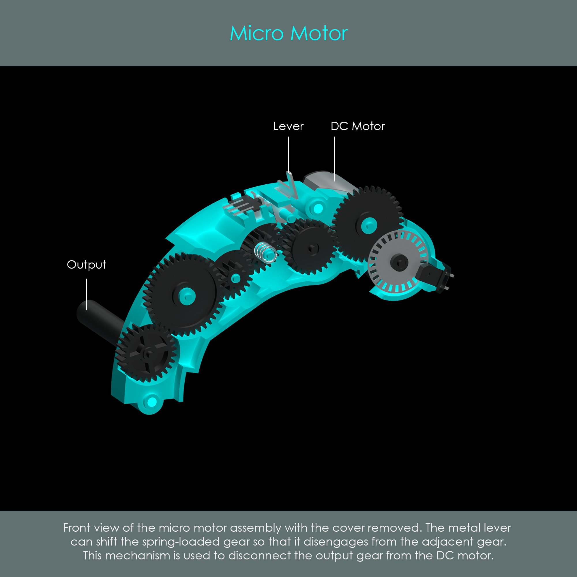
The DC Micro Motor has a lever to shift one gear between two positions. One position closes the gear train so that the motor's rotation is forwarded to the output gear, and the other position interrupts the transmission of rotational force. A tiny metal spring holds this switching gear under slight pressure so that it remains in its default position engaged with the other gears. Only when the AF/MF switch on the barrel is moved to the MF position, the lever shifts the switching gear so that it disconnects from its adjacent gears, disconnecting the motor from the output gear. This type of transmission shows that the DC Micro Motor does not support full-time manual focus override.
An exploded view of the DC Micro Motor shows some more details of the unit. The rotor shaft is connected to a small pulley which drives another pulley via a rubber belt. This belt drive helps reduce vibrations that might be induced by the motor's operation. The larger pulley is connected to the first gear of the reduction gearbox. An encoder wheel with numerous tiny openings alongside its perimeter is attached to the first gear. Each transition between an opening and solid material is one step of the encoder wheel. A sensor runs an infrared beam through one of these openings, and records the signal on the other side. Once the wheel is turned, the signal is interrupted until the next opening where the signal is recorded again. This setup allows the lens electronics to count the number of steps the encoder wheel has turned and thus how far the focusing lens group has been moved.
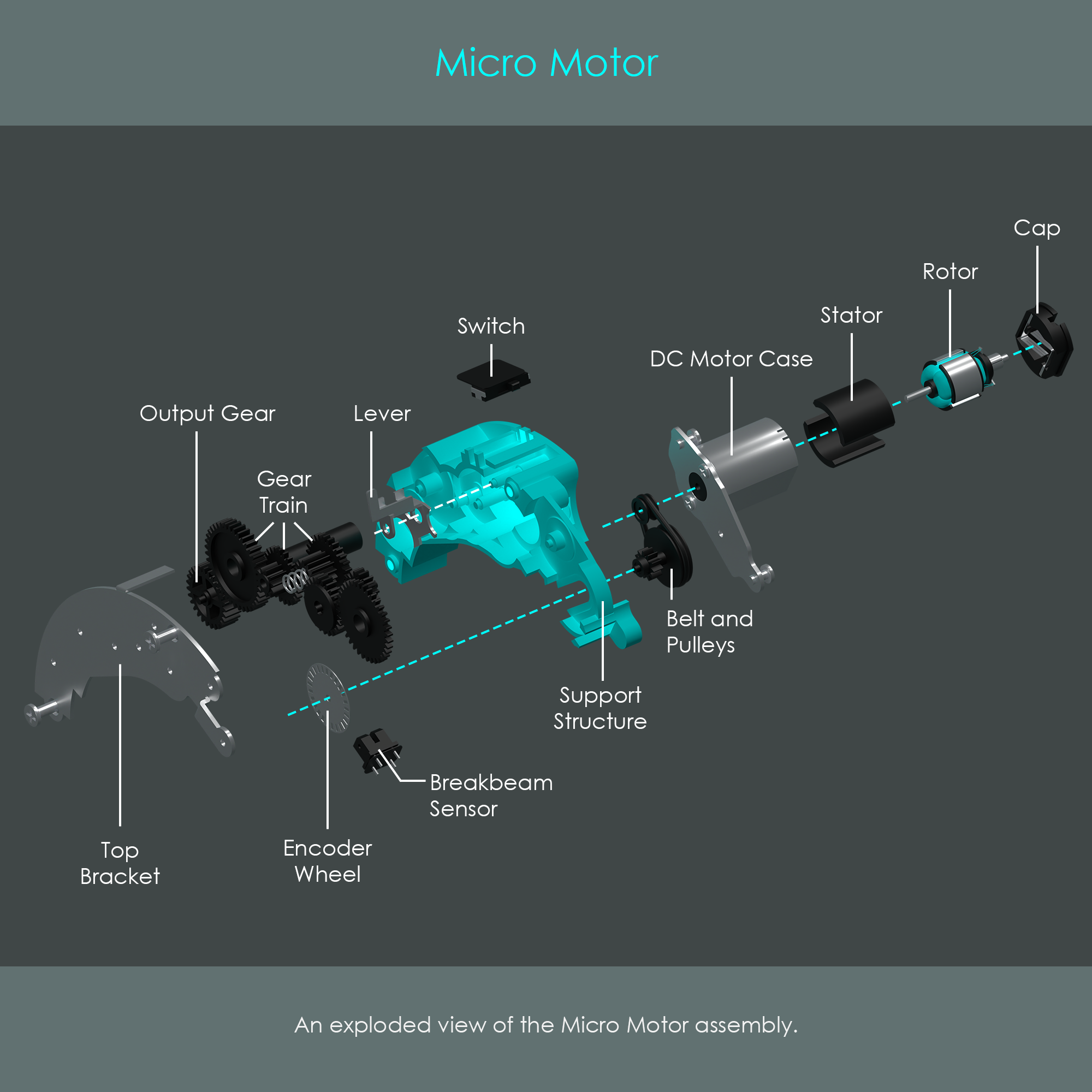
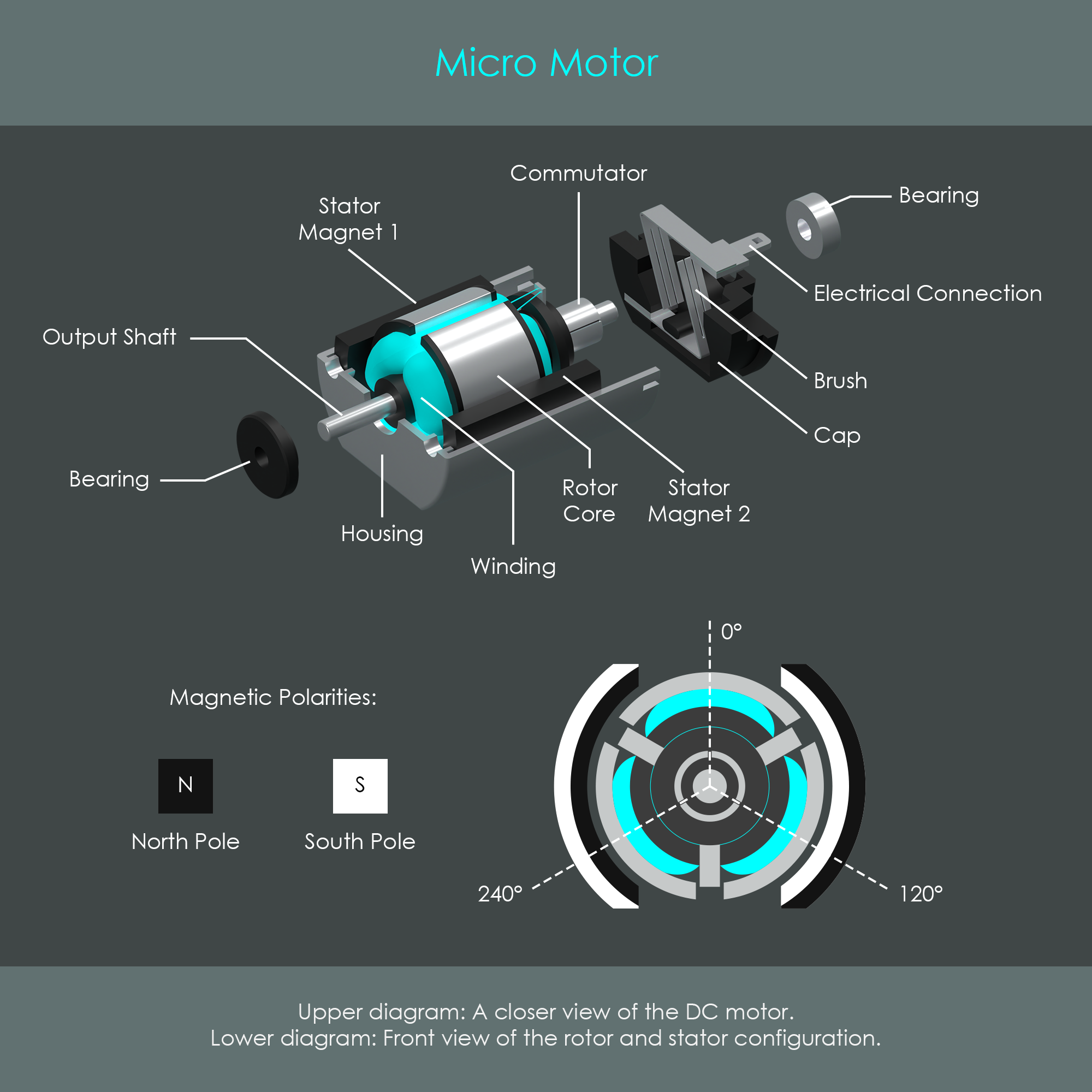
The exact type of motor is a 2-pole 3-coil brushed DC motor. The description 2-pole refers to the two connection terminals at the back of the motor. These connections directly lead to the two metal brushes that touch the rotor's commutator from opposite sides. This is how electrical power is supplied to the rotor. The description 3-coil indicates that the rotor has three coil windings attached to its metal core. Each of these coils is an electromagnet that can change its polarity.
The following schematic shows the electrical configuration of the rotor. The commutator has three separate contact surfaces, and these are connected to the windings as depicted. As the brushes are 180 degrees apart, they only form electrical connections with two of the contact areas at a given time. This design is the key requirement for the coils to form correctly oriented magnetic fields.
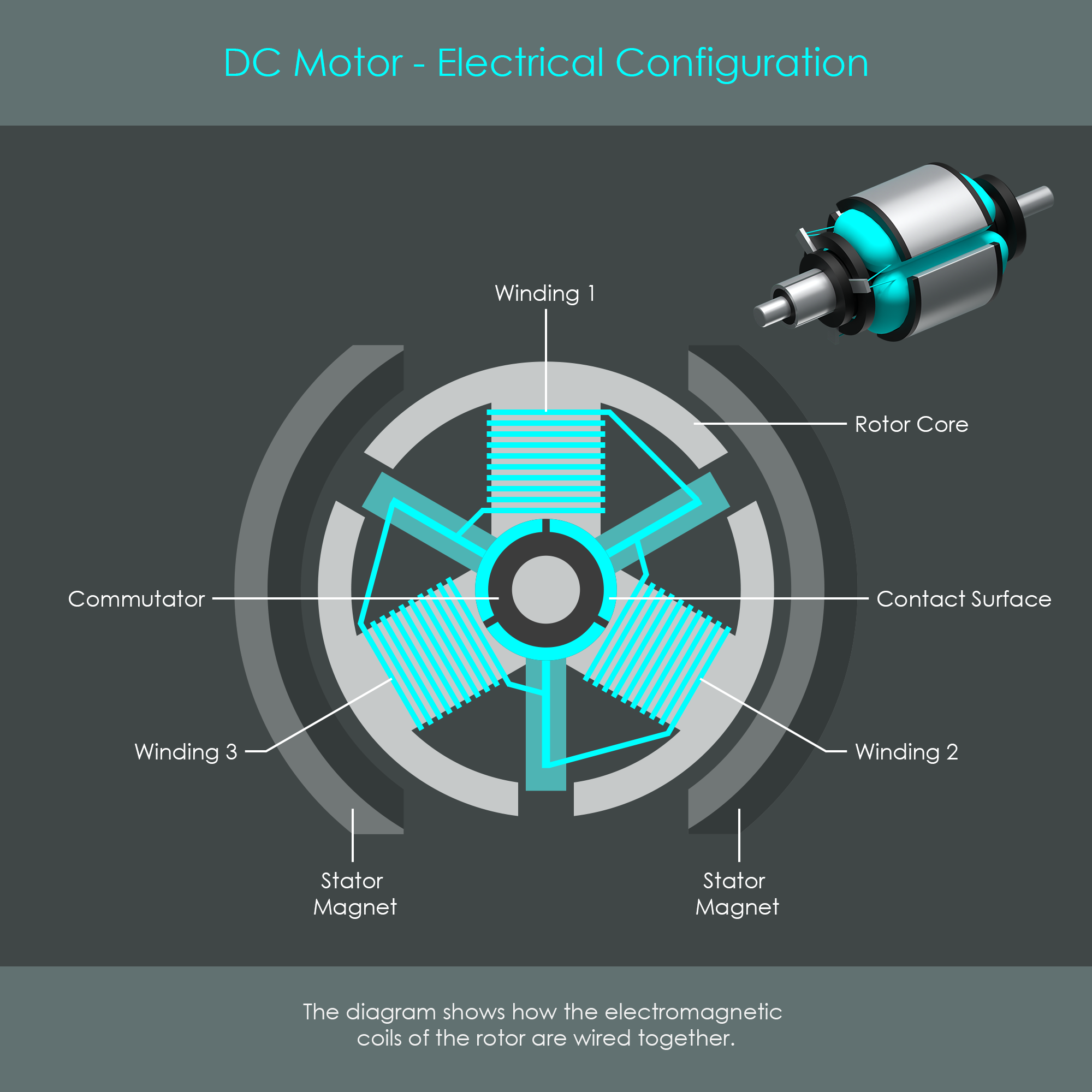
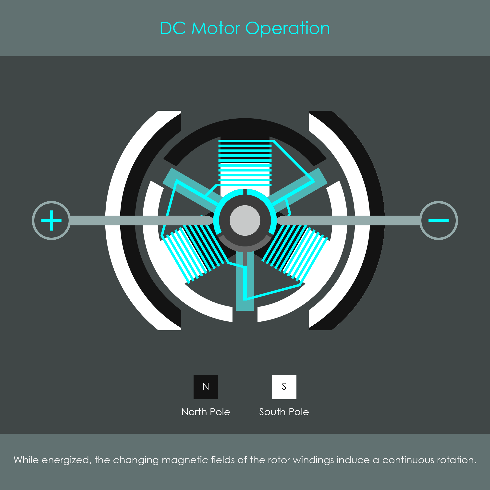
The two power terminals of the DC motor are energized with an operating DC voltage between 4 and 6 volts. The metal brushes pass on this voltage to the commutator, which in turn applies that voltage to the coils. The magnetic fields produced at each coil are either repelled or attracted by the stator's permanent magnets. Due to the commutator's design and the wiring configuration, each coil changes its electrical (and therefore magnetic) polarity as soon as it has reached maximum proximity to a permanent magnet. This switches the coils from being attracted to being repelled, ensuring a continuous rotation. This principle allows a small DC motor to run at speeds up to 6.000 rpm. When the voltage polarity of the brushes is reversed, the rotor turns in the opposite direction.
The advantage of the DC Micro Motor is that it runs on a DC voltage, and therefore does not require any complex driver electronics such as a stepper motor. Nevertheless, the control circuitry must be capable of handling comparatively large currents. Due to its limited torque, the DC Micro Motor is almost always used in compact lenses with smaller and lighter focusing lens groups. Another disadvantage of this autofocus drive is its relatively noisy operation. Nevertheless, it is a reliable autofocus system that is embedded in numerous Canon lenses.
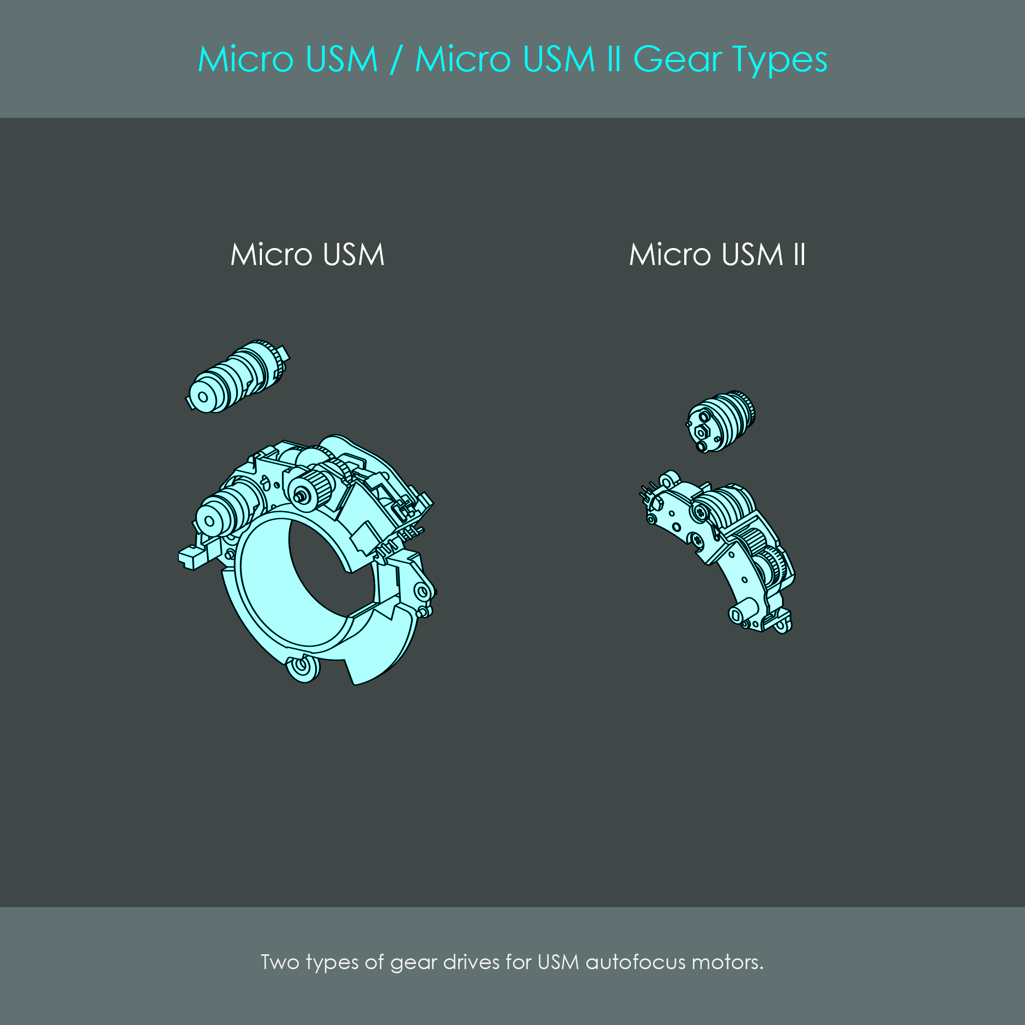
The Micro USM and Micro USM II are different members of Canon's ultrasonic motor family. The first generation Micro USM was introduced in 1992. Ten years later in 2002, the second generation Micro USM II followed with an ultra-compact design half the size of the original version.
Canon's Micro USM actuators are small-diameter (11 mm) cylindrical ultrasonic motors using piezoelectric ceramic elements to generate oscillations. Compared to the ring-type USM, the Micro USM uses an ultra-compact design. The original Micro USM version has an overall length of 26.7 mm whereas the Micro USM II is just 13.4 mm long. Both versions of the Micro USM have an output gear that engages with a speed-reducing and torque-increasing gearbox that is connected to the focusing cam barrel.
The Micro USM motor in general is a stack of different parts pressed together via a metal shaft. The motor can be divided into the rotor, the stator, and some auxiliary parts and support structures. The attachment flange is usually described as the top of the unit.

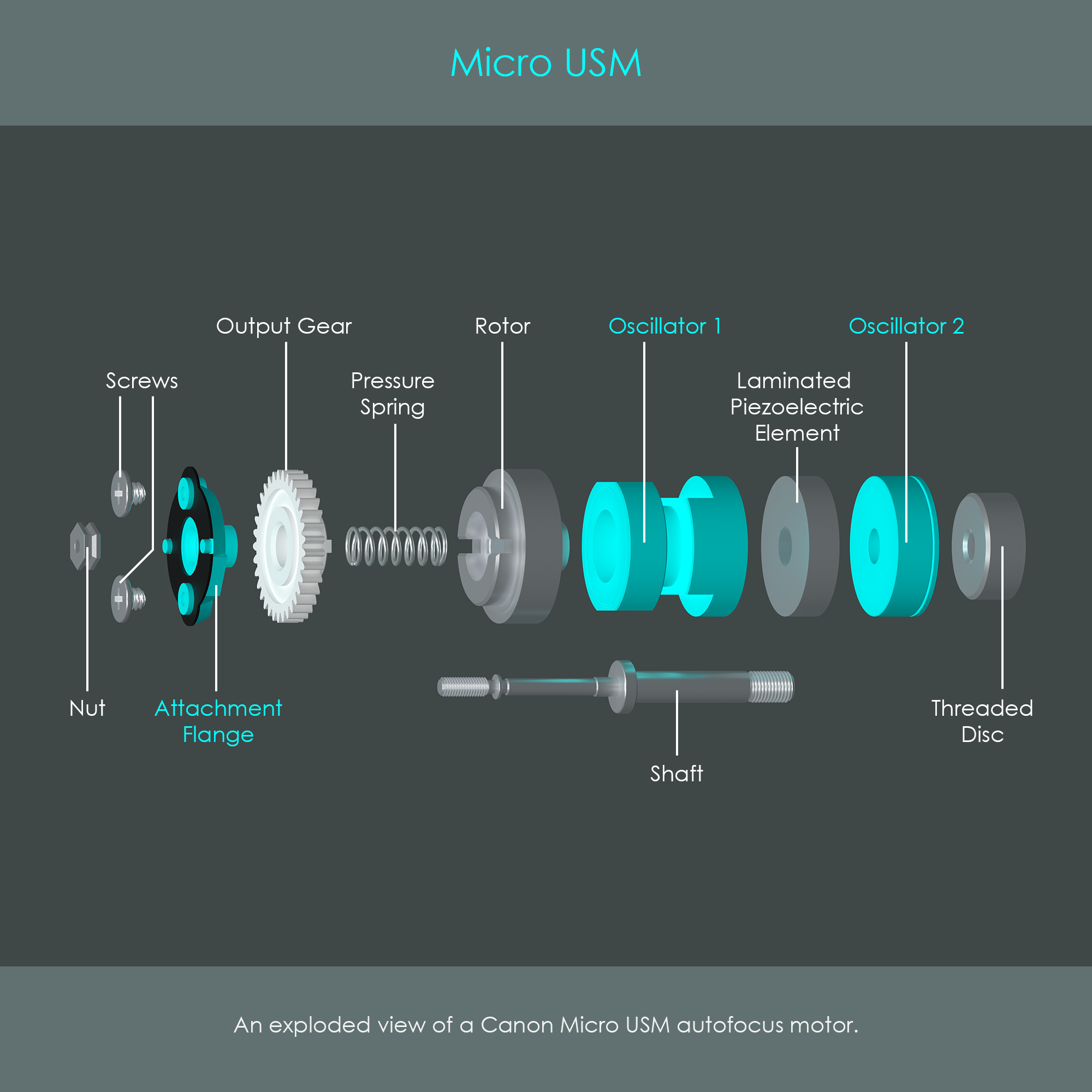
The illustration shows an exploded view of the Micro USM unit (original version) inside a Canon EF lens.
Both versions of Micro USM autofocus drives use piezoelectric elements to generate ultrasonic vibrations in the stator. While this principle is similar to the ring-type USM, the Micro USM type of motors use an entirely different stator design.
The Micro USM uses piezoceramic discs to generate ultrasonic vibrations in the stator. As the vibrations of each individual disc are extremely small in amplitude, a stack of round 25 discs is laminated to a solid piezoceramic part. The resulting multi-layer cylindrical unit is called the laminated piezoelectric element (LPE). The illustration is a schematic view of one piezoceramic disc.
The two halves of these discs have been polarized in opposite directions. Each disc has four electrodes attached to either side, two on each half. This allows the discs to be energized in two phases A and B. If an electric voltage is applied to one phase, the electric field that forms across the electrodes causes one quarter of the disc to expand and one quarter to contract. This electrically induced deformation of piezoceramic material is referred to as the inverse piezoelectric effect. The reaction of piezoceramic material is roughly 10 times higher in the expanding way rather than in the contracting way. In the illustration, the level of deformation is hugely exaggerated to illustrate the principles involved.
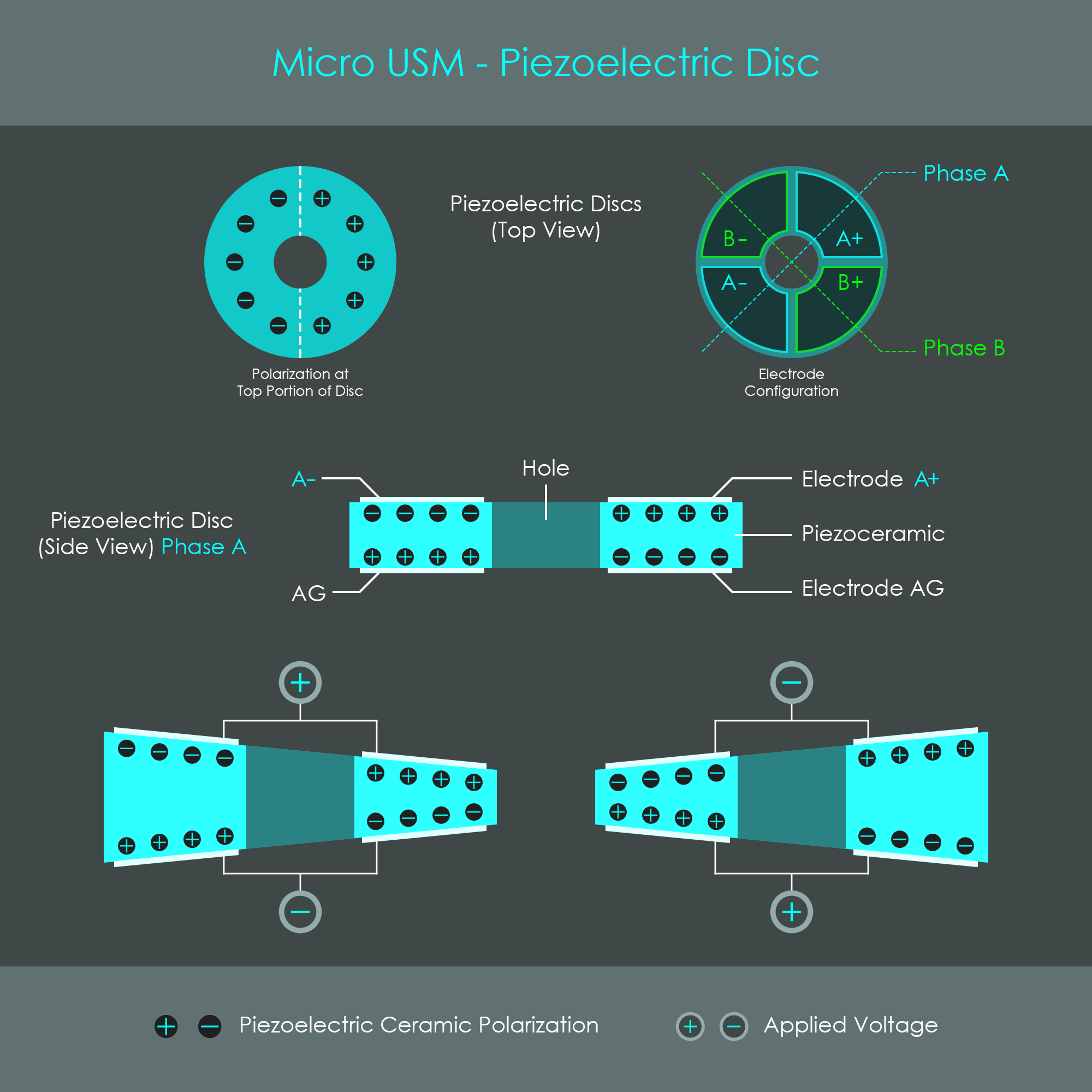
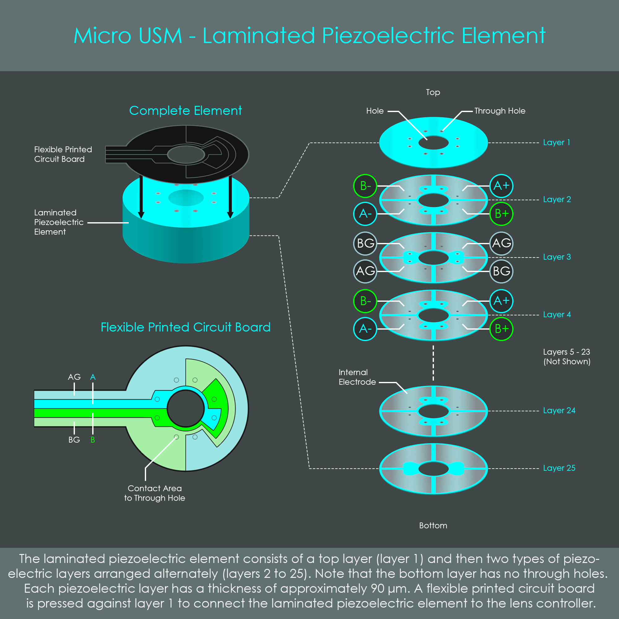
The illustration shows the arrangement of discs inside the laminated piezoelectric element, and how electrical power is supplied to each disc. Layers with even numbers have their A+/- and B+/- electrodes on their top, while layers with uneven numbers (except for the first one) have AG and BG electrodes on their top. Each disc has a number of through-holes, tiny conductive paths that establish electrical connections between the different layers. Note how some electrodes are shaped with recesses so that there is enough space for through-holes into deeper layers of the stack. The discs and through-holes are arranged so that energizing the A-phase (applying a voltage between the A and AG contacts) will energize all the A-phase portions of all discs at the same time. The same applies for the B-phase. This synchronized activation of all discs causes a uniform deformation of the entire LPE. Electrical power is provided via a thin sheet of printed circuit board that is pressed against the top surface of the LPE, establishing a connection to all of the through-holes of that first disc. The individual layers are not visible to the naked eye.
With the LPE sandwiched between the two oscillator bodies, energizing the LPE with a sinusoidal voltage causes the oscillators to vibrate. Vibration is amplified by exciting the stator with the natural resonance frequency of the oscillators which is in the ultrasonic range. The illustration shows how the stator vibration even causes a lateral displacement of the stator body.
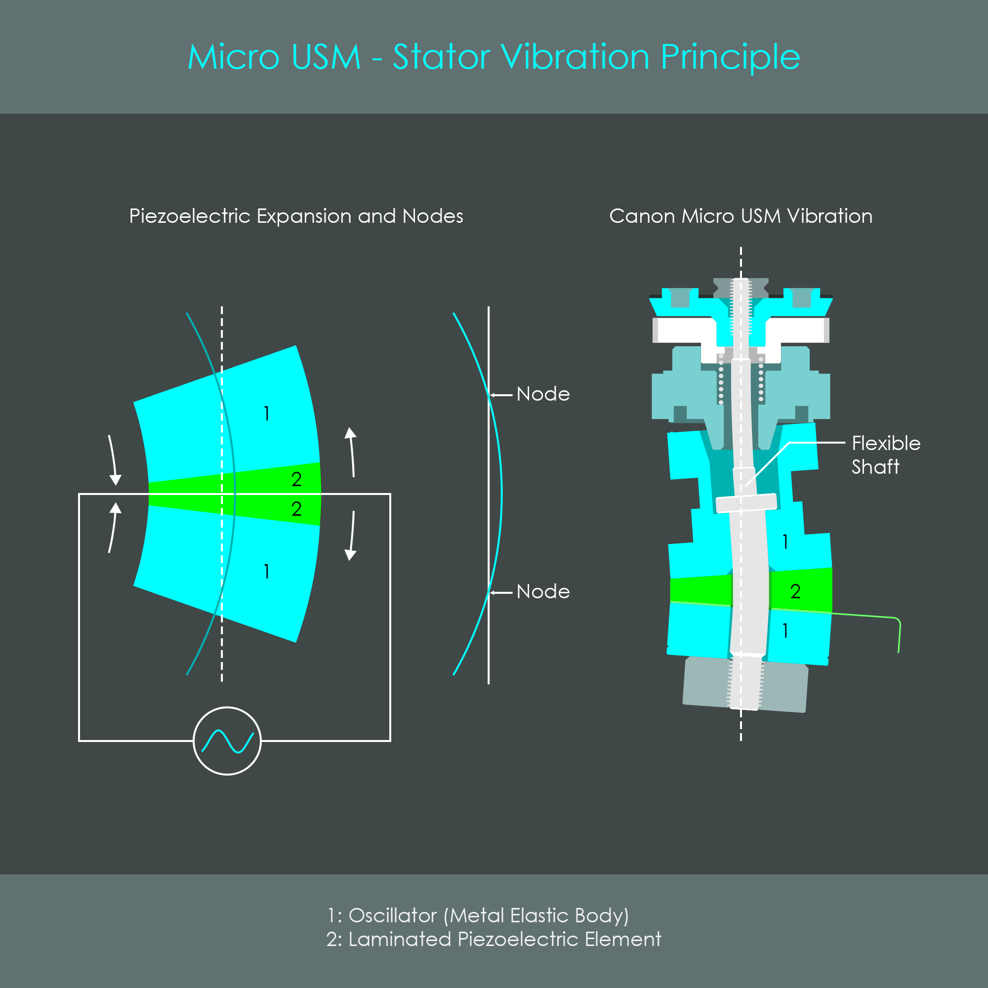
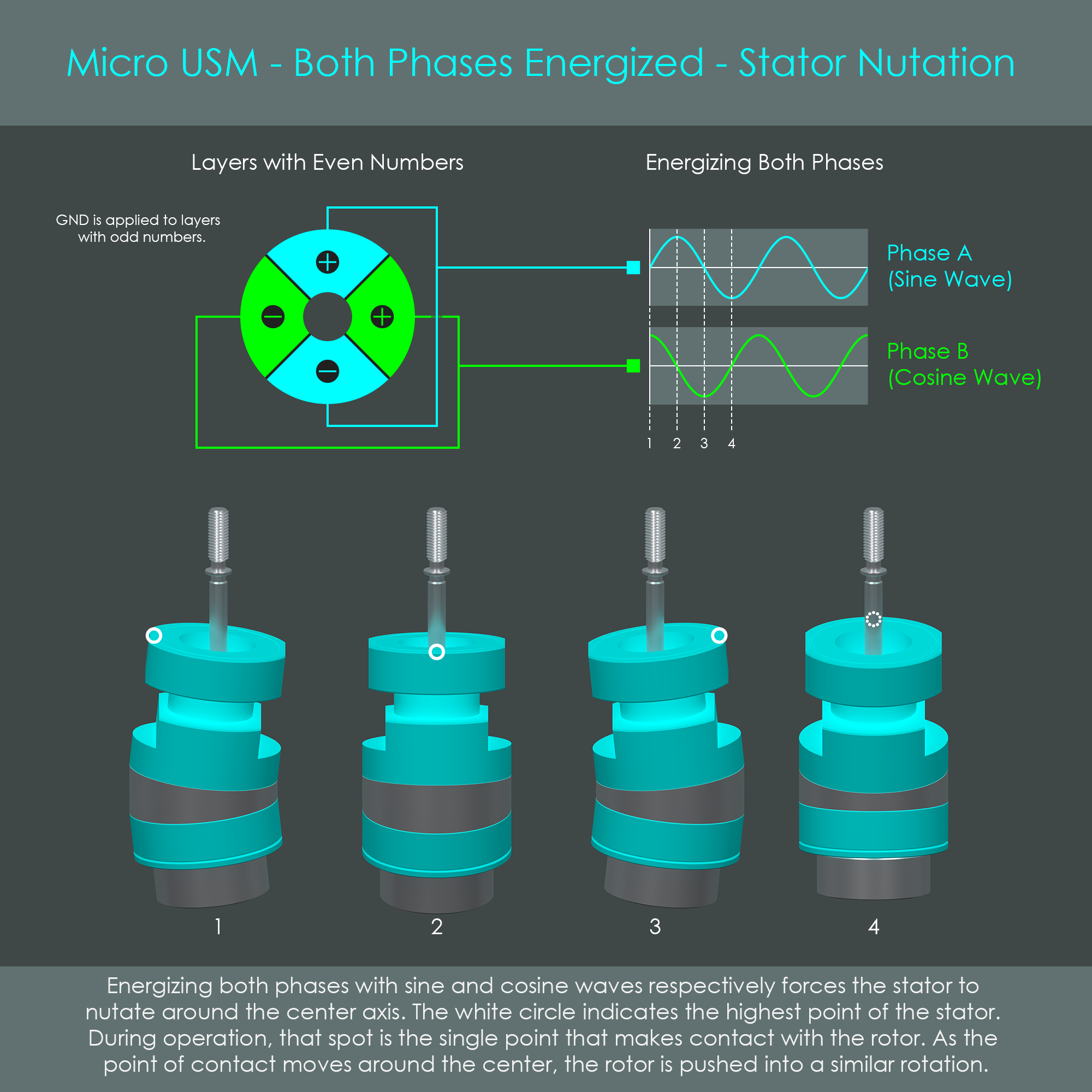
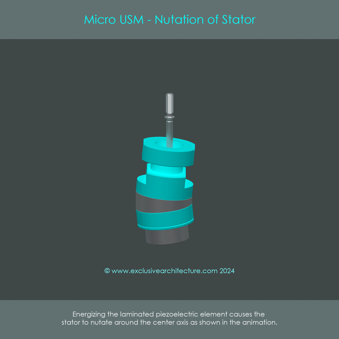
The two phases of the LPE are energized with high-frequency voltages that are shifted by λ/4 (temporal phase shift). The resulting vibrations from each phase combine and generate a nutation motion of the stator around its axis. This nutation forms a peak at the top surface of the larger oscillator that moves around the circumference similar to a traveling wave. The amplitude of that oscillation movement is as small as two micrometers, and therefore not visible to the naked eye. The oscillator has a small lip on its surface that is in pressure contact with the rotor.
The animation shows the nutation movement of the stator. The rotor and output gear, among other parts, are not shown here to most clearly illustrate the movement. The nutation is slowed down and greatly exaggerated in amplitude. Note that the stator itself does not rotate around its axis but only the peak on the top surface of the larger oscillator travels in a circular way. This traveling wave (one peak and one valley) is the source of rotational energy that is transferred into the rotor via friction.
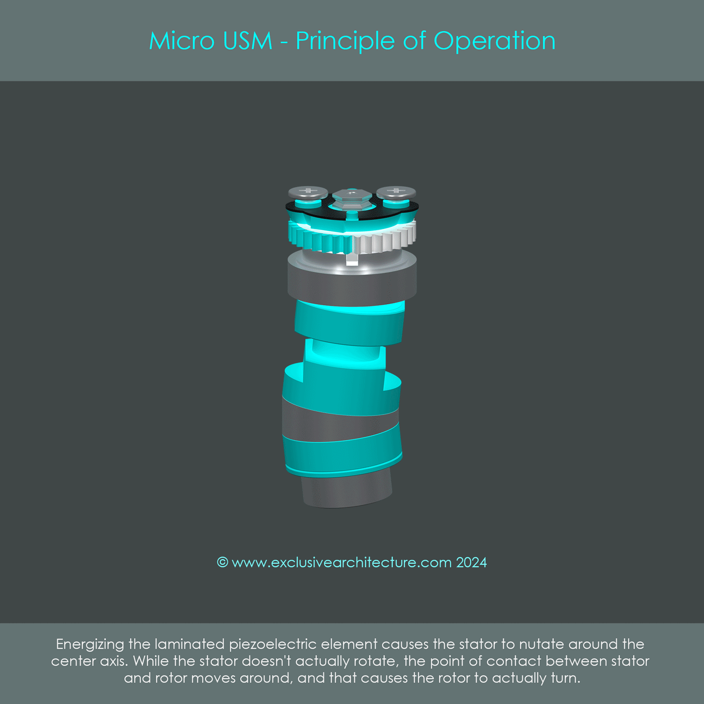
This animation shows the complete Micro USM unit in operation. The principle of transferring the stator's energy into the rotor is similar to the frictional coupling used by the ring-type USM motor. The Micro USM rotor is in pressure contact with the top surface of the elastic body. Proper operation is achieved only when the stator is excited at the exact resonance frequency of the elastic metal bodies, which amplifies vibrations and thus energy transfer into the rotor. Although the Micro USM stator has no teeth cut into the oscillator body, the traveling wave exerts frictional force in the opposite direction of the nutation motion. This principle of frictional coupling is very similar to the ring-type USM. The animation shows that the rotor and output gear perform actual rotations around their axis, and their direction of rotation is opposite from the direction of the stator's traveling wave.
The cylindrical ultrasonic motor operates a two-stage energy conversion process: In a first stage, electrical energy is converted into a nutation motion of the stator. In a second stage, these ultrasonic vibrations are converted into a continuous unidirectional rotating movement of the rotor by friction on the stator. The stator vibrations are generated by a multi-layer laminated piezoelectric element that is excited via two separate phases that are excited with a λ/4 phase-shifted sinusoidal voltage, generating the nutation mode. The stator's energy is transferred to the rotor due to friction between the stator and rotor, caused by the pressure contact (preload force) between stator and rotor.
This summary is similar in many respects to the summary of the ring-type USM motor. While the Micro USM and ring-type USM share the same general principles, they are still different types of motors. Here is a comparison of the similarities and the differences between the Micro USM and the ring-type USM:
Both types of motors use piezoelectric elements to generate flexural vibrations in the stator, as well as ultrasonic excitation to maximize vibrations in the oscillators. A traveling wave is generated at the surface of the stator, and friction is used to turn the rotor in the opposite way than the traveling wave. Both types are inaudible by the naked ear, but their noise can be picked up by sensitive microphones during video recordings. Neither of them is intended for long-term operation.
Ring-type USM and Micro USM types of autofocus drives use completely different stator geometries. Also, their piezoceramic elements are arranged in different ways. The stator of a ring-type USM forms seven to nine traveling waves whereas the stator of a Micro USM performs a nutation motion that is similar to a single traveling wave (one peak and one valley). The overall size of the Micro USM is considerably smaller than the ring-shaped USM. Output speed is relatively high on the Micro USM, and therefore a gearbox is used to lower the speed of the output gear. Overall production cost is comparatively low for the Micro USM and Micro USM II, which is why these types of motors have been used for the low- and mid-level lenses.
The following illustration shows two gearboxes used to connect Micro USM and Micro USM II motors to the focusing groups of lenses. Some examples of Canon lenses that use Micro USM and Micro USM II technology include:
In June 2012, Canon announced the EF 40mm F2.8 STM and the EF-S 18-135mm F3.5-5.6 IS STM lenses. These were the first lenses that carried the designation STM in their name, an abbreviation that stands for stepper motor. Although the technology had already been used in the Arc-Form Drive, the stepper motor inside STM lenses has a clearly different design including a greatly reduced size.
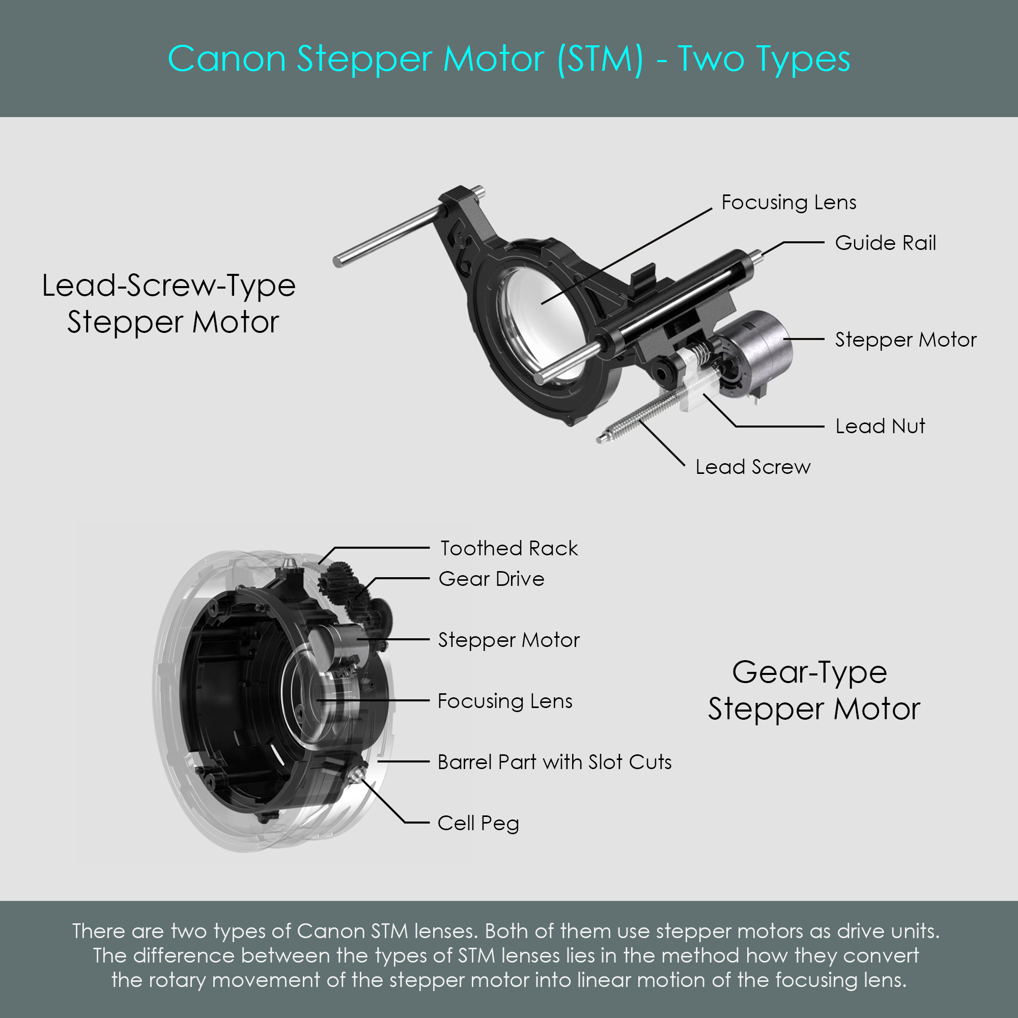
Stepper motors are rotary drives that convert electrical energy into rotational energy of the motor shaft. Canon uses two different transmission types to convert the rotary motion into linear motion of the focusing lens groups:
While these are different types of transmissions, the actual stepper motors used are identical. Canon STM lenses offer very quiet and smooth autofocus operation. For that reason, the STM autofocus system is considered a good choice for both photography and video shooting. The STM system has become widely used not only in Canon's EF and EF-S series of lenses but also in their latest RF and RF-S lenses. Here is a short list of lenses that use the STM autofocus system:
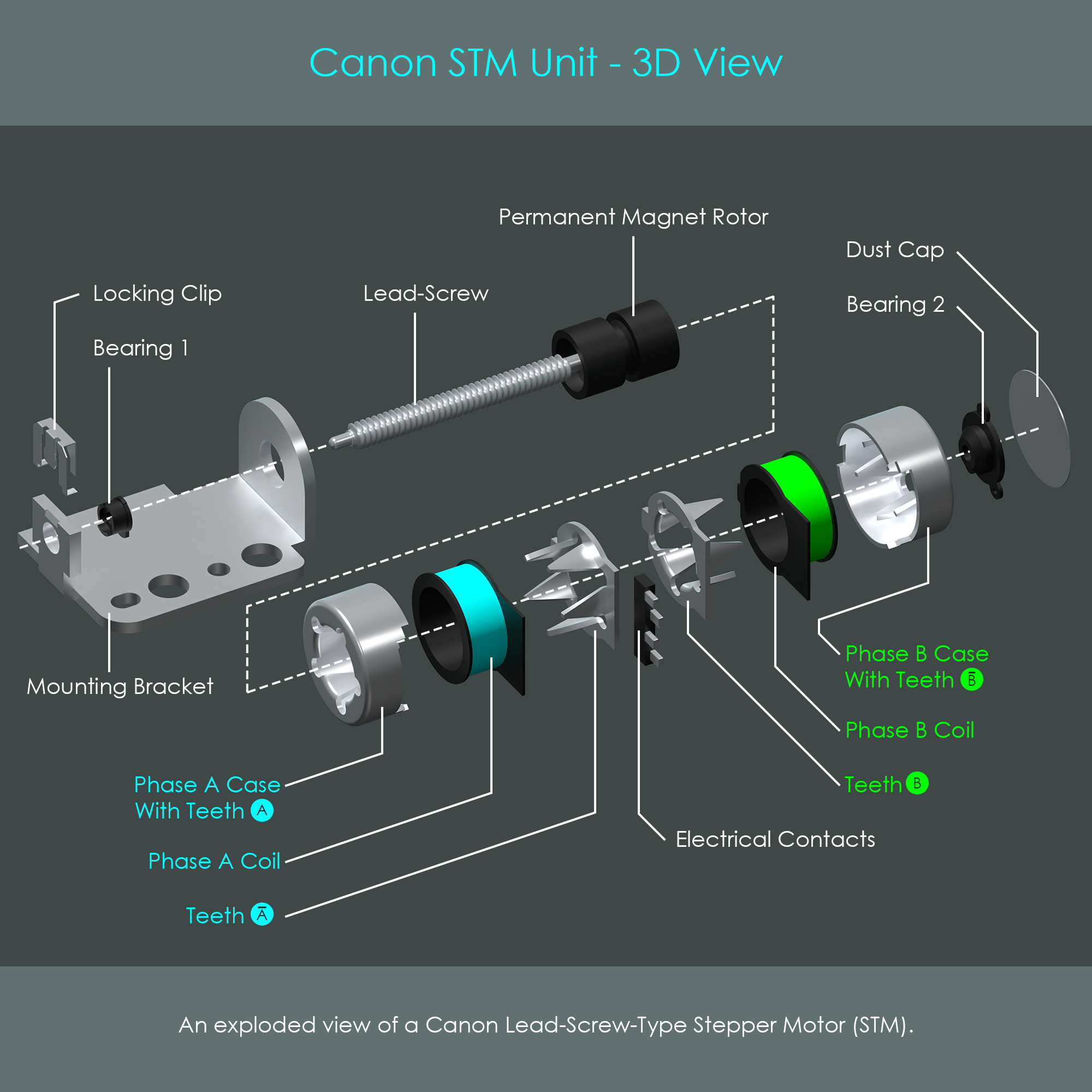
The type of stepper motor used in STM lenses is a 2-phase bipolar stepper motor with permanent magnet rotor. Unlike the AFD stepper motor, the STM version uses a rotationally symmetrical stator. First, the general principle of stepper motor operation is shown, and then the actual design of Canon's stepper motors is examined.
The following illustration shows the general principle of a 2-phase bipolar stepper motor. The term 2-phase refers to the use of two separate coils. The description bipolar indicates that each of these coils can be energized with current flowing in two different directions, allowing each coil to generate two opposite magnetic field polarities. The ferromagnetic metal parts of the stator pointing towards the rotor are called field poles. The coil windings of both phases are split into two portions and are wound around opposite field poles to ensure simultaneous magnetization during operation. Each phase is labeled with two letters, one of them overlined to indicate the polarity in which the magnetic field is generated. Once phase A is energized, the magnetic polarity of field pole A and field pole Ā (Inverse-A) is always opposite from each other. The same applies for the second phase. In the illustration, the letters are also used to describe the polarities at which the voltage is applied to the coils.
In this simplified example, the stator consists of four field poles, two per phase, which results in a rather large step angle of 90 degrees. During operation, the two phases are energized as shown in the timing diagram below. Note how due to inverted polarities, the two coils are capable of generating four different magnetic field orientations, and the stator strictly follows these orientations. This mode of operation is called full-step mode. Four full steps are required to complete one turn of the rotor. The stepper motor can also be driven in half-step mode where between full-steps both phases are turned on at the same time, turning the rotor by 45 degrees. Eight half-steps are required to complete one turn of the rotor. In the context of autofocus systems, however, speed is more important than increasing the step precision, and therefore the half-step mode is not discussed further.
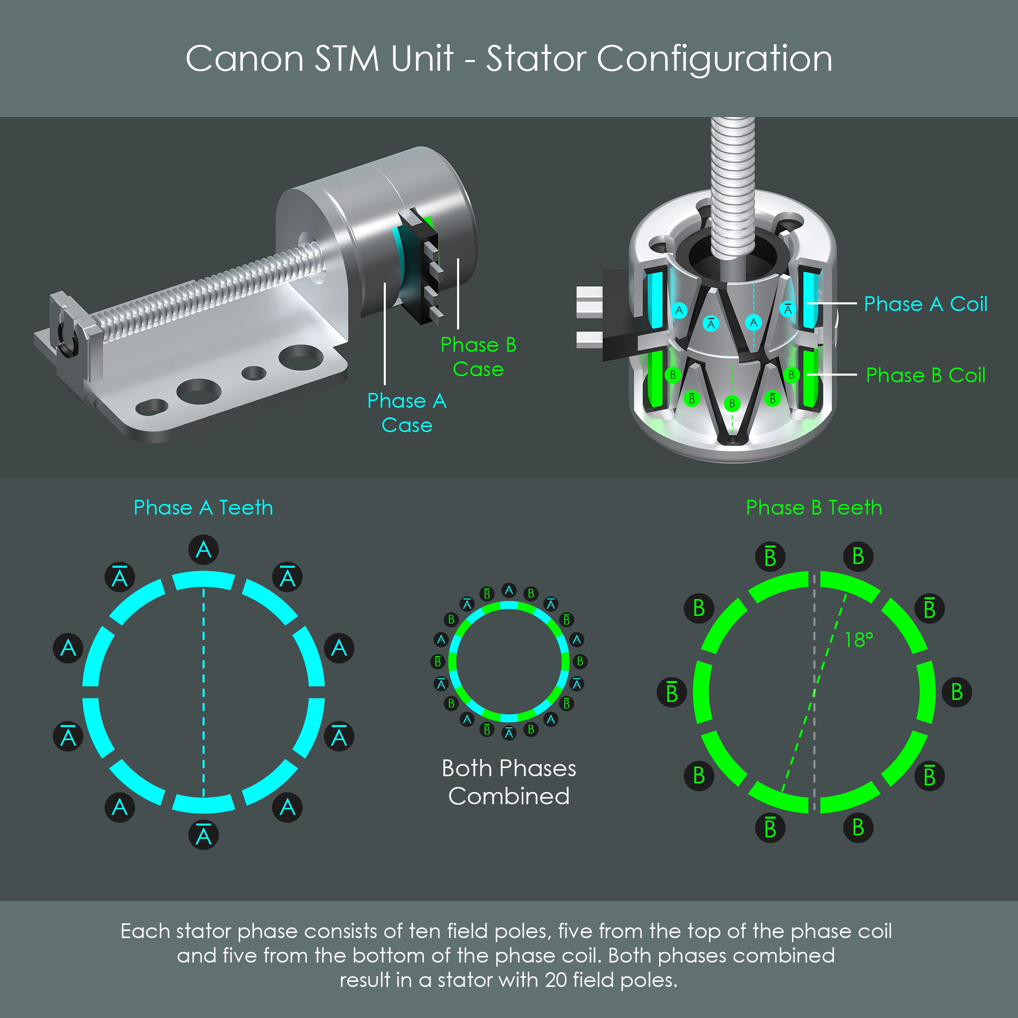
The type of stepper motor used in Canon's STM lenses has 20 field poles, 10 per phase. This quantity of field poles makes it unpractical to apply coil windings directly at each field pole. For that reason, a very clever stator design is used:
The two phase windings are stacked on top of each other as shown in the cutaway diagram. Each phase winding is surrounded by a steel shell, and triangular teeth (field poles) are brought to the center. These teeth are arranged in an alternating fashion, five coming from the bottom of each coil pointing upwards, and five coming from the top of each coil pointing downwards. Once a coil is energized, the steel shell carries the magnetic flux into the teeth, one polarity to the teeth pointing up and the opposite polarity to the teeth pointing down. As a result, the teeth form an alternating ring of north and south magnetic poles and will attract the permanent magnet rotor accordingly.
Thanks to this design, one coil winding has a total of 10 field poles. Phase B is located below and has an equal number of 10 field poles. One key requirement of this design is that both rings of phase A and phase B stator teeth are offset by 18 degrees from each other. This is half the pitch between two teeth of one stator. This stepper motor construction is also referred to as can-stack design because it looks like a small stack of two steel cans. Another commonly used term is tin-can design.
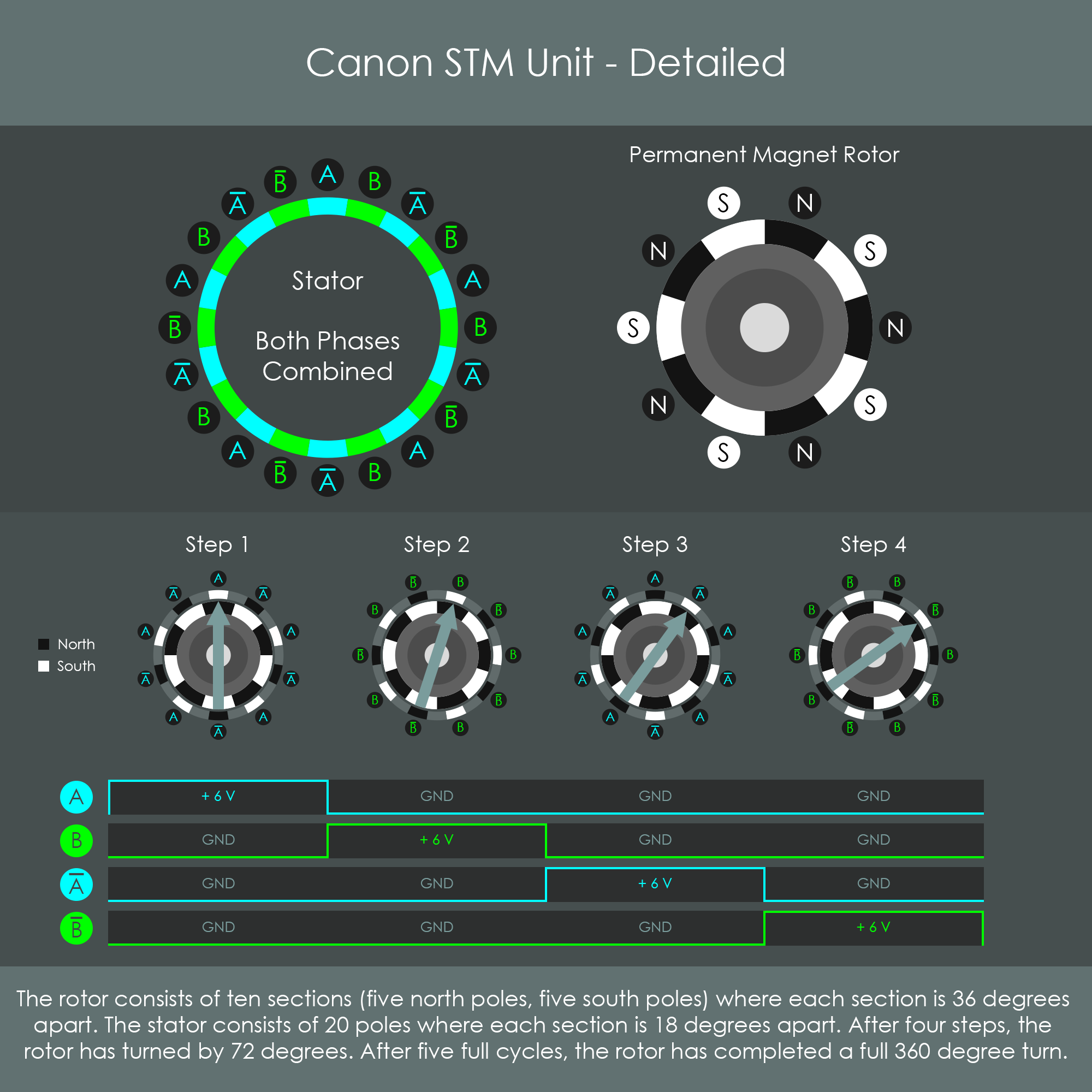
Once all teeth of phases A and B are combined, the stator consists of 20 field poles. The rotor is a ferrite ceramic cylinder that is magnetized in the 10-pole pattern shown (five north and five south poles). The stepper motor is operated via four repetitive steps:
After four steps, the rotor has completed a 72 degree turn, and thus it requires 20 steps to complete one full rotation. The direction of rotation can be reversed by performing the sequence of steps backwards. The rotor follows the magnetic fields so precisely that no separate feedback control system is required. The autofocus control system of the lens sends an instruction to the stepper motor driver to perform a certain number of steps. After the same number of electrical pulses to the phase coils, the rotor will have performed an equal number of steps into the desired direction.
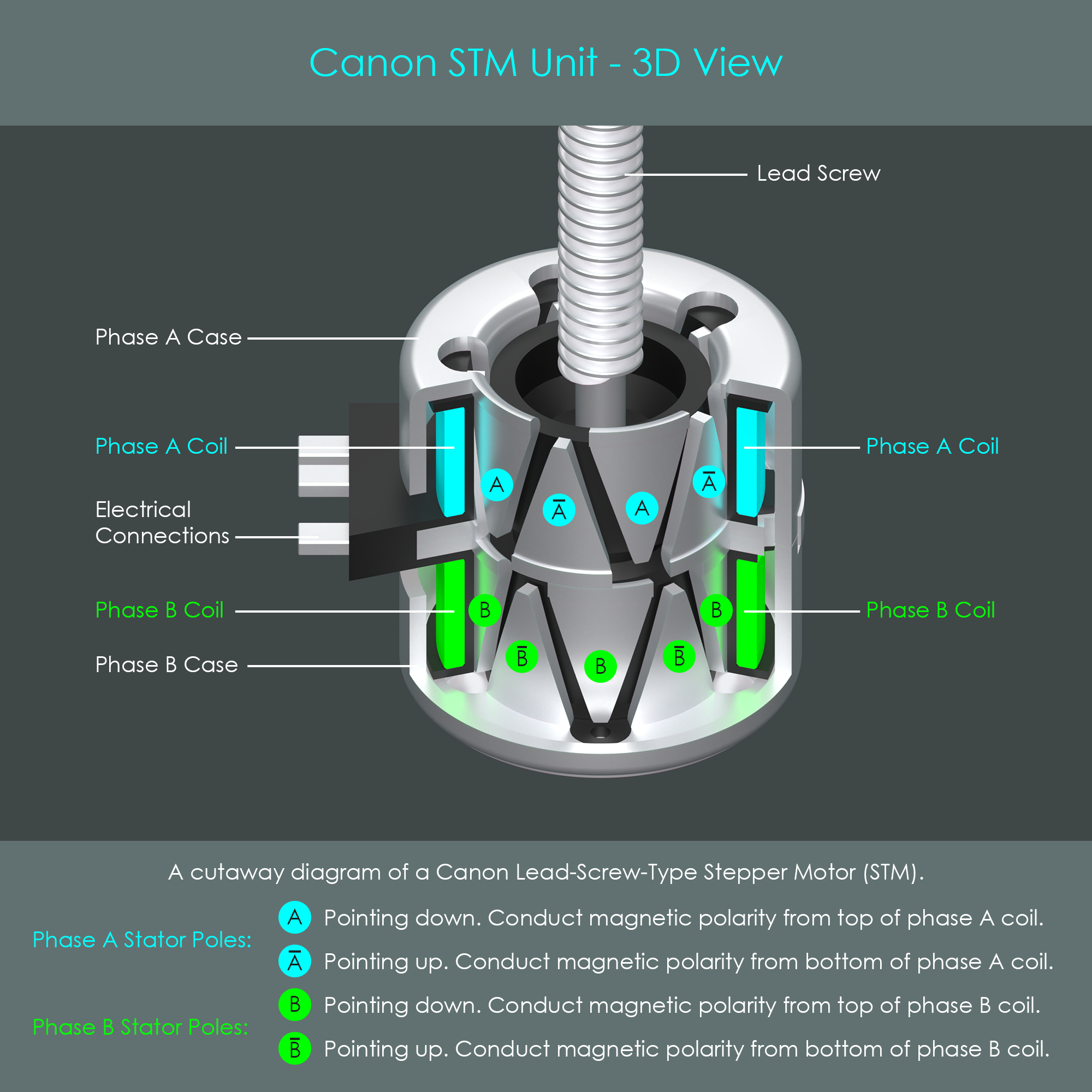
The can-stack is one of the most commonly used stepper motors designs. It is often used in scanners, printers, CNC mills, robots, and other devices. The illustration is an enlarged cutaway diagram of a stepper motor used in Canon's STM lenses. This is an extremely small unit of just eight millimeters diameter (this is smaller than the DC micro motor). Due to this size, the STM drive is more suitable for smaller focusing lens elements. It is therefore unlikely to ever be used in heavy super-telephoto lenses.
Canon STM lenses use focus-by-wire as the coupling method between the manual focusing ring and the autofocus drive. For that reason, all STM lenses do support full-time manual focus override at any time.
The following illustration is an exploded view of the stepper motor used in Canon's STM lenses. The long worm gear on the motor shaft is part of the lead-screw mechanism to move the focusing lens.
The Nano USM autofocus drive is the latest addition to Canon's ultrasonic motor family. Canon announced the EF‒S 18‒135mm F3.5‒5.6 IS USM lens, the first Canon lens with the new Nano USM technology installed. In that same year, Canon discontinued the previous ultrasonic motor – the Micro USM.
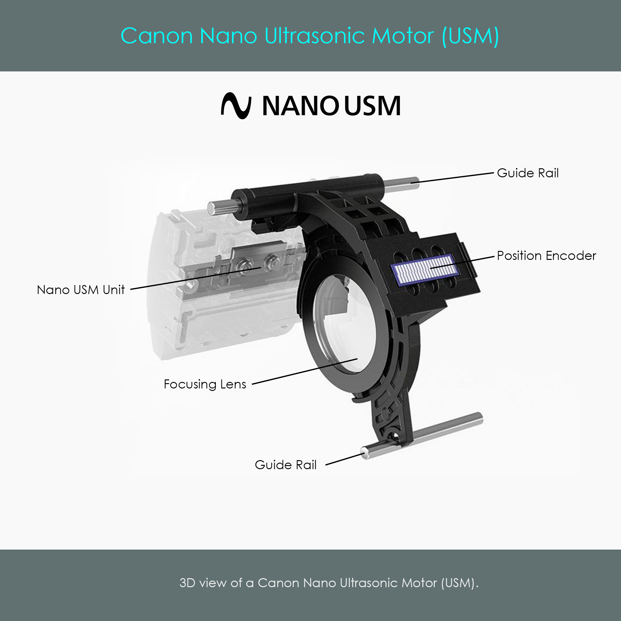
The Nano USM uses piezoceramic elements to generate vibrations that are translated into movement. The drive system does not generate rotational output, and therefore doesn't require a helical barrel or lead screw to translate rotation into linear movement. Instead, the Nano USM generates a linear movement that is directly forwarded to slide the focusing lens cell axially along guide rails. A position encoder with alternating dark and reflective stripes is attached to the focusing lens unit, allowing an infrared sensor to count the steps that the focusing mechanism has moved.
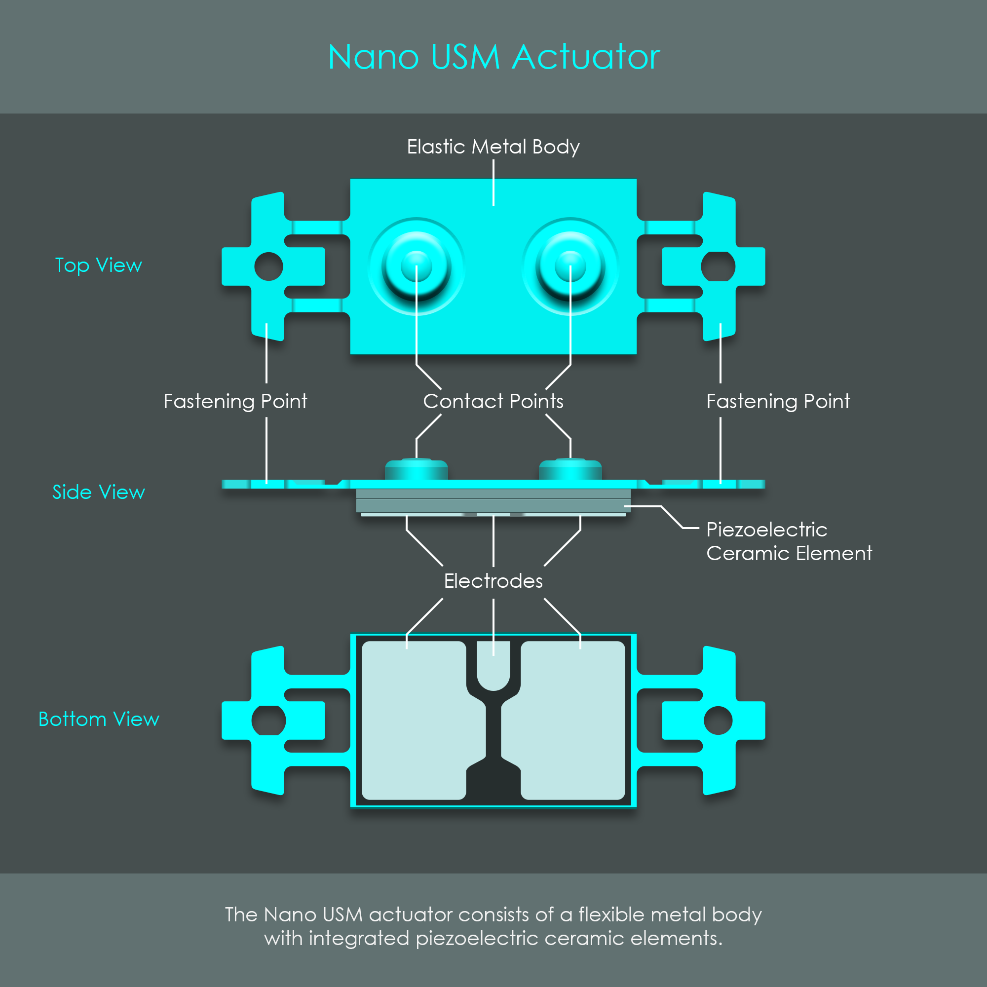
The heart of the system is the Nano USM actuator. That is a tiny piece of elastic metal around 20 mm in length with piezoceramic elements attached to its lower side. The piezoceramic layer has three electrodes on the lower surface. Two small elevations on the top surface are in pressure contact with a stationary slide rail. The illustration summarizes this construction of the Nano USM actuator.
Although being extremely small, the Nano USM actuator generates comparatively high levels of output torque. In addition, it offers very rapid start and stop characteristics and fast, well controllable output speed.
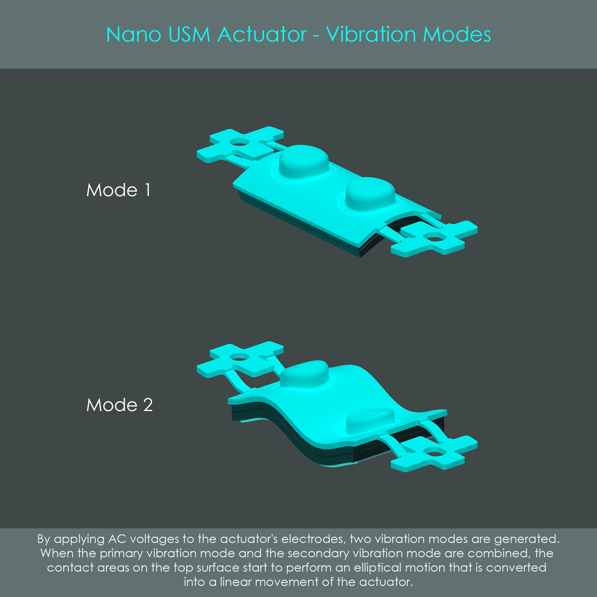
During operation of the Nano USM drive, the USM actuator goes into two flexural vibration modes. Mode 1 is an out-of-plane bending mode that turns the actuator into a saddle-shape. Mode 2 is another out-of-plane bending mode that shapes the actuator into a waveform.
Both modes are excited with high-frequency voltages in the range of the natural resonance frequency of the elastic metal body. The result is that both vibrational modes combine and generate an elliptical motion of the contact points. Due to the pressure contact between the Nano USM actuator and the stationary slide rail, the elliptical motion exerts a frictional force on the surface. It is the counterforce on the actuator that ultimately generates the linear movement of the Nano USM frame.
The amplitudes of both bending modes are greatly exaggerated in the illustrations. In reality, the amplitudes are so small that no deformation can be seen during operation. Similarly, the ultrasonic frequencies involved in the excitation of the actuator are inaudible to the human ear, and unlikely to be picked up by microphones. Due to its slightly lower output power, the Nano USM is preferred when smaller groups of lens elements need to be moved.

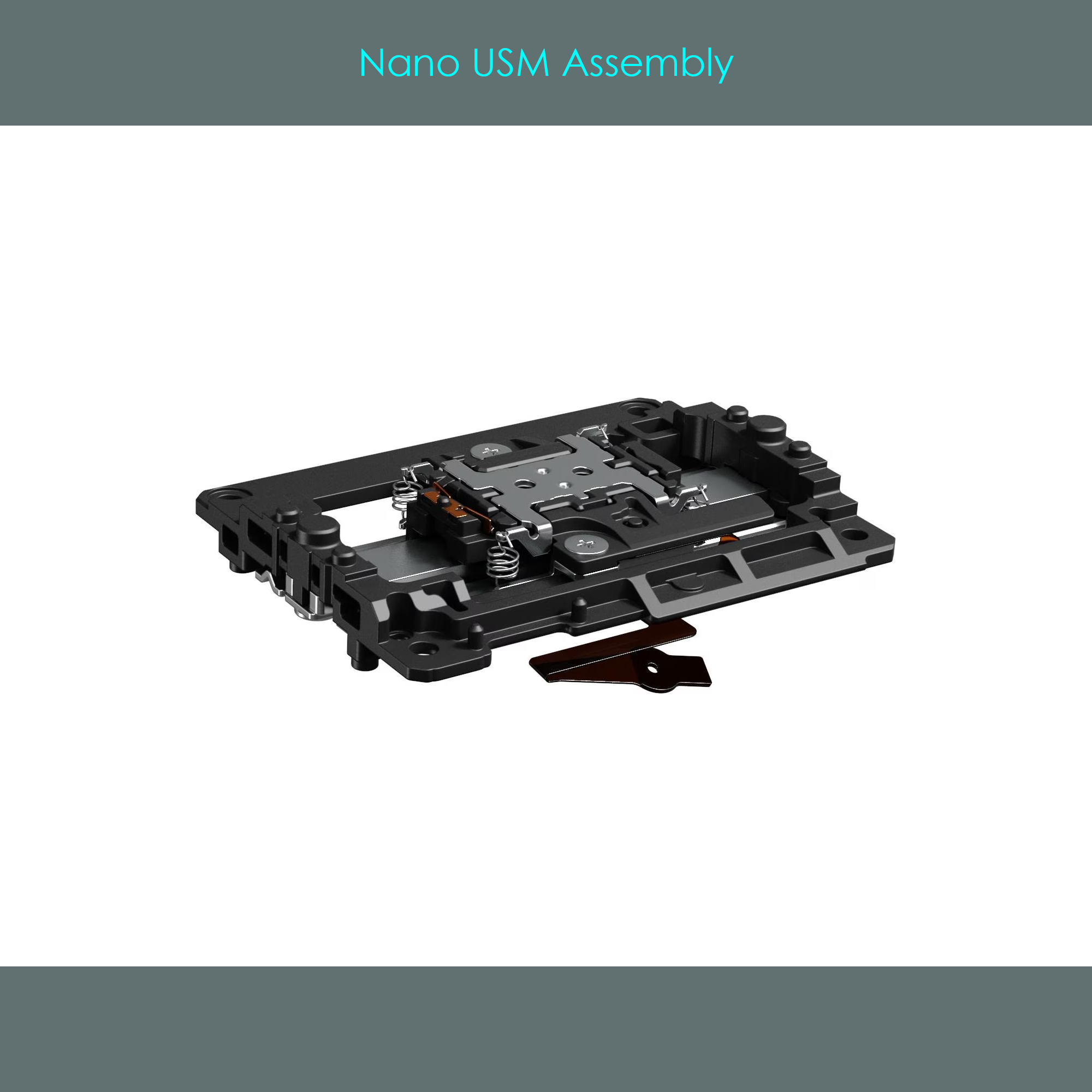
The image shows a complete Nano USM assembly including the frame, the actuator socket, the slide rail, and the silver bracket that holds down the Nano USM actuator via four tension springs.
Canon's lenses with Nano USM autofocus drives allow full-time manual focus override via focus-by-wire. There is no mechanical connection between the manual focusing ring on the lens barrel and the focusing lens group inside a Nano USM lens. This is similar to lenses with STM or VCM autofocus drives.
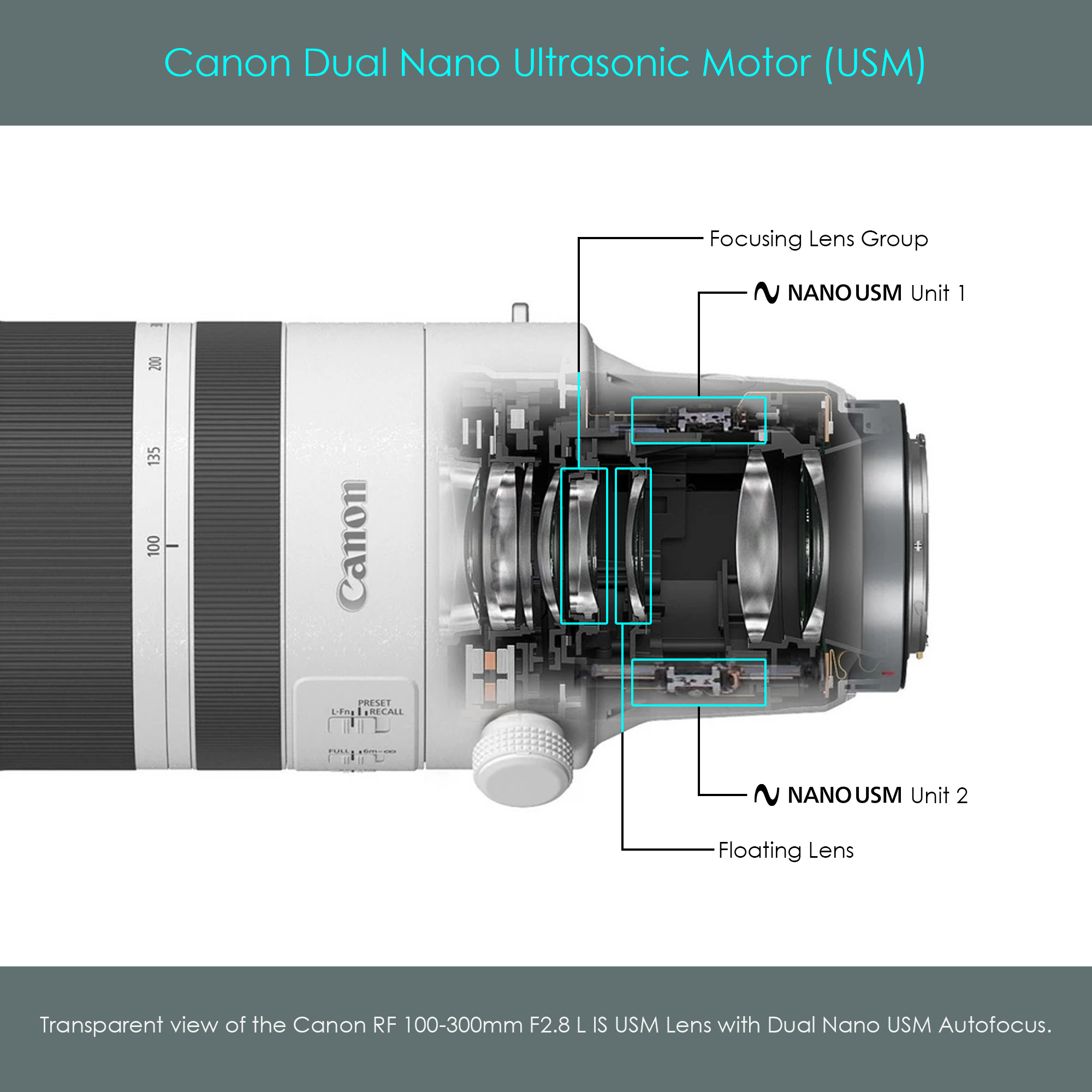
Released in 2019, the Canon RF 70-200mm F2.8L IS USM was the first lens to feature Dual Nano USM technology. The innovation with Dual Nano USM is that two of these compact ultrasonic drive systems are installed in the lens barrel. Each AF drive moves one of two internal focusing groups – one focusing group and one floating group. The image shows the Dual Nano USM system that is integrated inside the Canon RF 100-300mm F2.8 L IS USM lens, a high-end telephoto zoom lens.
The voice coil technology has a long history that is tied to the history of telecommunication. The first voice coil was patented at the end of the 19th century, but it was in the 1920s when the first voice coils were actually installed in telephone speakers. A wire coil was attached to a paper diaphragm, and a magnet was placed inside the coil. The resulting device was a transducer that converted electronic signals into the voice of the caller. This type of use gave voice coils their names. Over the last decades, voice coils kept their name but got increasingly used for other applications including hard disc drives, robotics, precision instrumentation, as well as camera systems.
Canon is already using voice coil motors for a long time to drive the image stabilization unit. Voice coil motors have also been used for decades as autofocus drives in cine lenses. This is ideal for video shootings because they are completely silent even in the ultrasonic range. Then, in 2024, Canon first used voice coil motors as the autofocus drives in their photographic lenses. The Canon RF 35mm F1.4 L VCM was the first lens with a voice coil motor.
Voice coil motors combine a range of advantages:
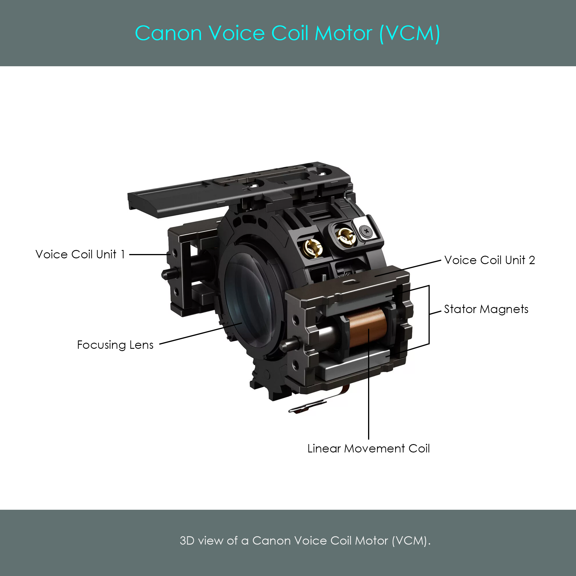
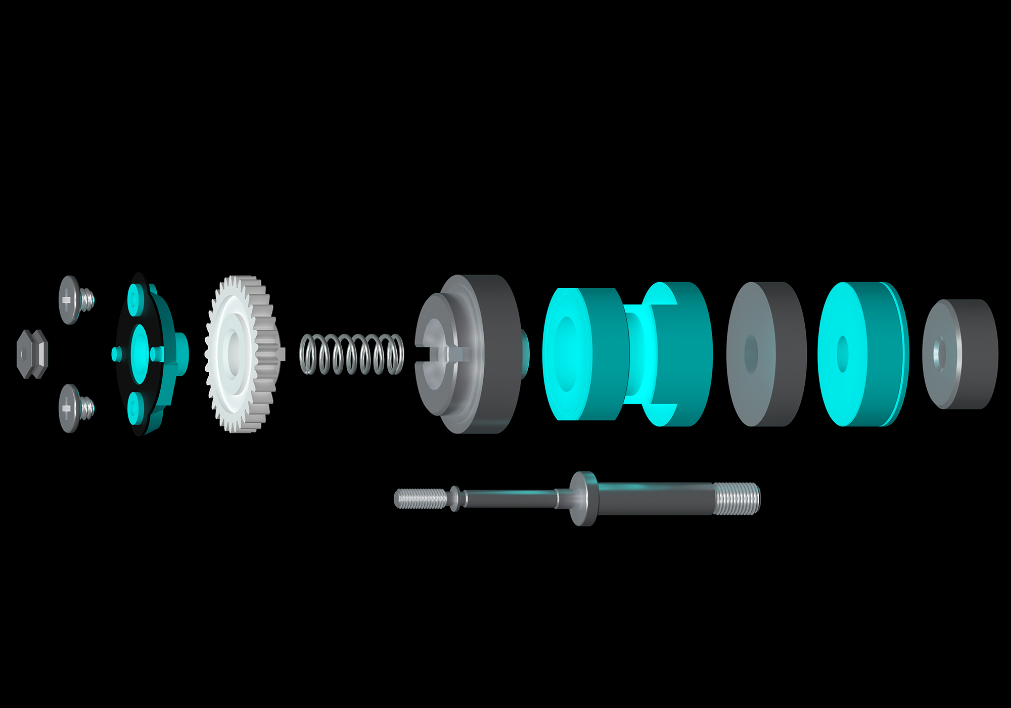
The image shows the VCM unit inside the Canon RF 35mm F1.4 L VCM lens. There are two identical voice coil motors attached to the focusing lens cell. This symmetrical construction prevents one-sided stress on the mechanism and therefore ensures a smooth sliding operation. Each voice coil is supported by a sliding rail that passes through its center and which defines the range of axial movement. On either side there are two strong permanent magnets placed above and below the voice coils so that their magnetic field runs through the coil.
The following illustration is a cross-sectional view of the VCM unit. The voice coil is exposed to the stationary magnetic field of the permanent magnets at any time. Once a current runs through the wire coil, a force (called Lorentz force) is exerted on the coil so that it moves axially along the sliding rail. The force generated is proportional to the flux density of the magnetic field and the intensity of the electric current. The direction in which the Lorentz force acts is depending on the direction of the current. By applying ultra-short voltage pulses to the voice coil, the unit can be driven into the desired direction with an extreme level of precision.
A slight drawback of the technology is that even when the focusing lens is not moved, the position control must be active in order to retain the coil's position.

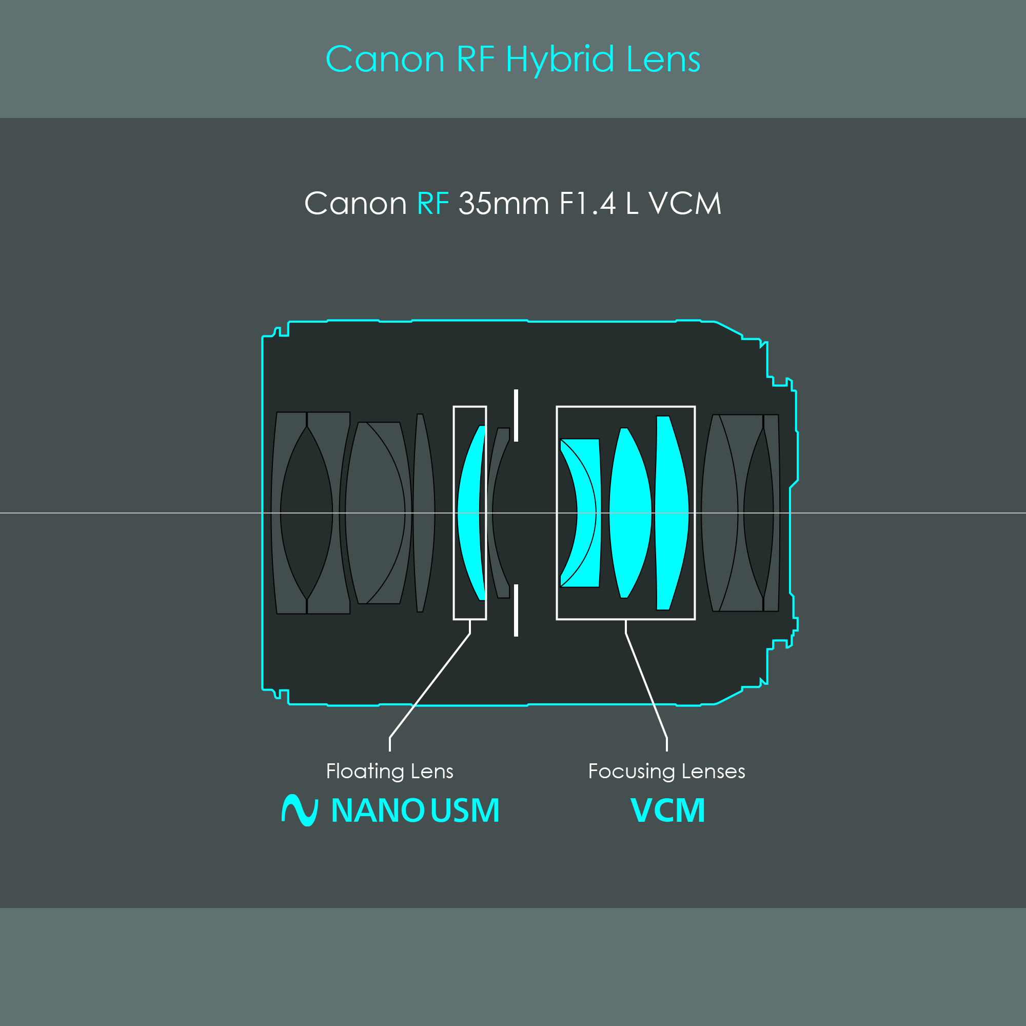
The use of voice coils in Canon's RF lenses made it possible to enter a new field. The smooth and silent operation of the VCM system not only convinces photographers but for the first time also satisfies the requirements of videographers. For that reason, Canon has introduced a new series of specially designed RF lenses, called hybrid lenses. These are L-lenses of the RF mount system that are specially designed to combine the benefits of photo and video technologies (such as a manual aperture ring normally found only on cine lenses). Some examples of these hybrid RF lenses include:
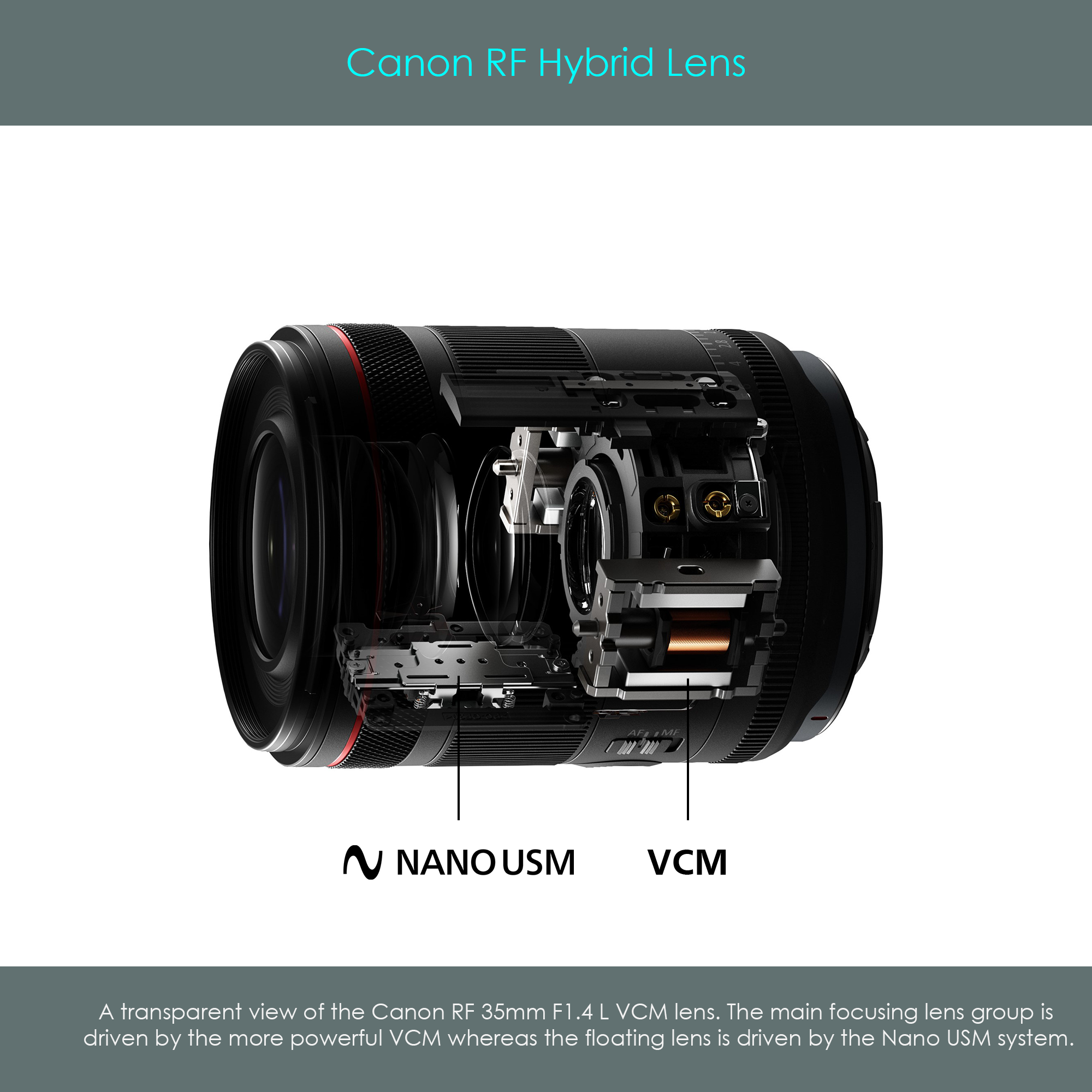
The illustration is a transparent view of the Canon RF 35mm F1.4 L VCM hybrid RF lens. It can be seen that this lens is equipped with two autofocus drive systems. The pair of voice coil motors drives the main focusing lens group while a Nano USM unit drives the floating lens element.
The following illustration is a block diagram of the same lens. Note that the main focusing lens group consists of four lens elements, a considerable weight that requires a powerful autofocus system. The two symmetrically arranged coils of the voice coil motor actually generate a significant force to even allow rapid movements of these focusing lenses. The floating lens is a single element only, and therefore the smaller Nano USM is a sufficiently powerful drive system.