If a camera is shaken during an exposure the resulting photograph is usually blurred. Image stabilization is an umbrella term for various technologies used to detect and counteract or even cancel user-induced camera shaking. This chapter describes the electromechanical device that is used to stabilize Canon's lenses.
The implementation of IS requires a considerable amount of hardware including advanced microelectronics as well as highly specialized software. For that reason, IS has only become available to the consumer market in the era of digital photography. Canon first introduced an image stabilizer in 1995 with the release of their EF 75–300mm F4–5.6 IS USM zoom lens.
For every photographer who shoots his camera handheld, unintentional camera shaking during the exposure can easily ruin a photo by introducing blur. The inverse focal length rule allows a photographer to determine the slowest shutter speed that can be chosen to prevent noticeable blur when shooting handheld. The slowest shutter speed can be obtained by taking the reciprocal of the chosen (full frame equivalent) focal length of the lens. For this reason the rule is also known as the "1/mm rule". A full frame camera with a 100mm lens attached to it should have it's shutter time not slower than 1/100 of a second if shooting the camera handheld. Any longer exposure with shutter speeds slower than 1/100 of a second might result in a noticeably blurred image. Shooting the same scene with a 400mm lens attached to the camera, 1/100 of a second is now way outside the limit for handheld shooting. With this long telephoto lens on a handheld camera, the shutter speed should be reduced to 1/400 of a second to still hope for a sharp photo. The reason therefore is that a small field of view magnifies the subject and therefore will show even small vibrations and shaking. Wide-angle-lenses, by contrast, are more forgiving in terms of shaking and can typically be shot handheld with much slower shutter speeds up to 1/10 sec. Keep in mind though that this is just a rule of thumb, and even within the limits of this rule, shaking might degrade the image quality.
The level of compensation achieved by an image stabilizer is typically specified in stops. In photography, a stop is a relative measure for the change in exposure. Adding one stop doubles the exposure of the image sensor while subtracting one stop halves the exposure. The addition or subtraction of stops can be achieved by the aperture of the lens, the shutter mechanism, or the ISO of the camera.
An image stabilizer does not add or subtract to the exposure of the image sensor. However, an image stabilizer allows to shoot 'outside the limit' determined by the inverse focal length rule. The number of stops an image stabilizer offers determines how many stops the shutter speed can be slower than recommended by the rule. If an image stabilizer offers two stops of compensation, a 100mm lens can still be used handheld with a shutter speed as slow as 1/25 of a second (1/100 × 22). Some of Canon's modern RF lenses offer optical image stabilization levels of four to five stops. A five-stop level of compensation allows the photographer to shoot with a shutter speed of 1/15 sec while achieving handheld steadiness as if he had used a shutter speed of 1/500 sec (1/15 * ½5 = 1/480).
With this technology implemented in a lens, shooting the camera handheld is still an option in darker environments.
There are two different concepts of image stabilization: In-Body Image Stabilization (IBIS) and Optical Image Stabilization (OIS). Both technologies are used to reduce camera shaking but they are implemented differently.
This type of shake compensation technology is embedded inside a camera's body. Canon's IBIS typically uses piezoelectric actuators to quickly move the camera's image sensor horizontally or vertically when the image is shifted due to camera shake. As the compensation occurs at the image plane, the optical path of light through the lens isn't changed. This system rather allows the camera's image sensor to 'follow' the image in case it is displaced by a shaking movement, and to record an image that doesn't show blur. The IBIS technology has been mentioned for the sake of completeness, but will not be described further.
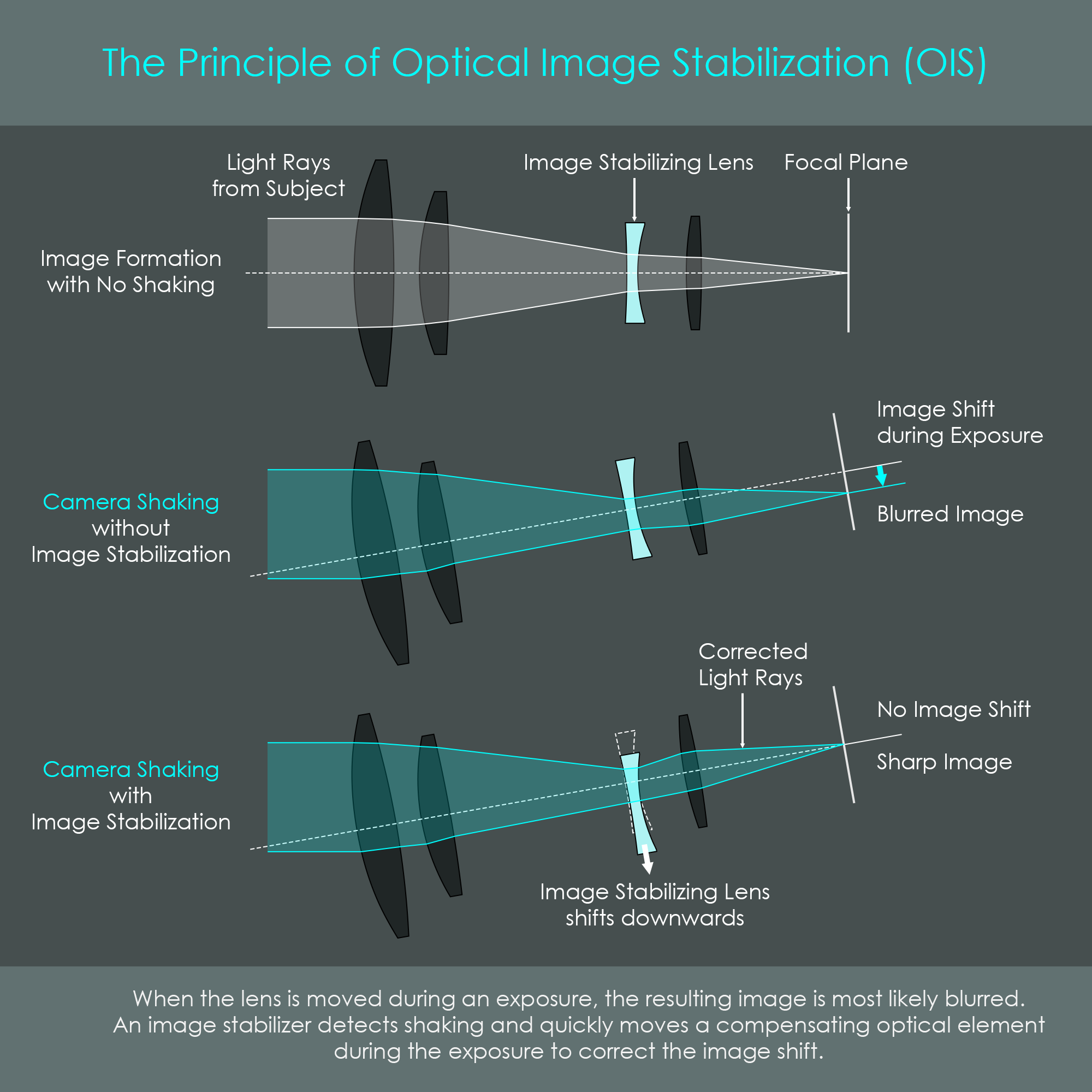
This type of compensation stabilizes the recorded image by quickly adjusting the optical path of the lens so that the image is formed in the intended position on the camera's image sensor. This is achieved by a dedicated image stabilizer unit inside the lens assembly. The image stabilizer unit consists of a shifting lens cell with dedicated compensation optical elements that can be shifted horizontally or vertically. An optical image stabilizer usually compensates for unintended pan and tilt movements of the camera, as well as combinations thereof. The stabilization is active when the camera's shutter is pressed halfway and during the exposure while the shutter is open. Naturally, only blur caused by camera and lens movements can be corrected to a certain extent, whereas blur caused by moving objects cannot be compensated at all.
Not every Canon lens is equipped with an image stabilizer. Some large-aperture (also called fast) prime lenses and wide-angle lenses including fisheye lenses usually are not available in image-stabilized versions.
A combination of modern optical image stabilization and in-body image stabilization can offer levels of compensation of up to eight stops.
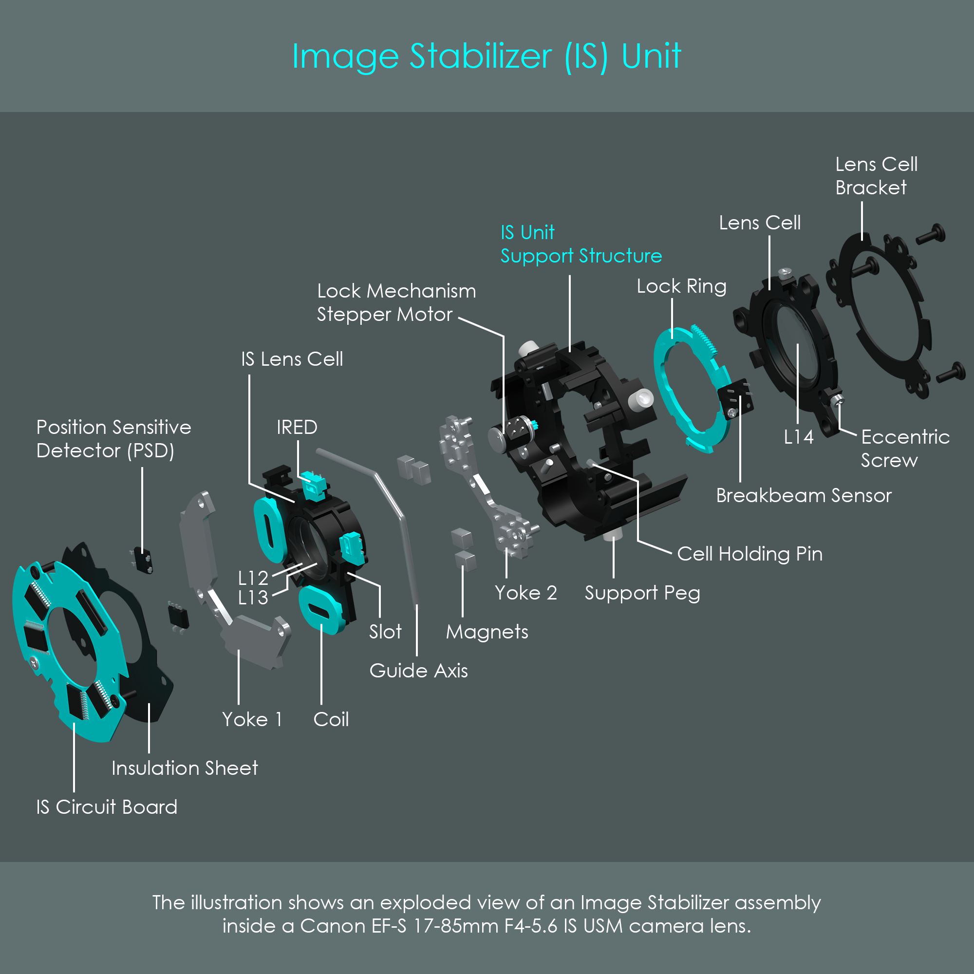
An IS unit as used in Canon lenses is a complex electromechanical device that is designed to move compensating optical elements orthogonally to the optical axis if shaking is detected. The following illustrations show a two-axis IS unit inside a Canon EF-S 17-85mm F4-5.6 IS USM zoom lens. The IS unit consists of various sub-groups of elements that will be explained below.
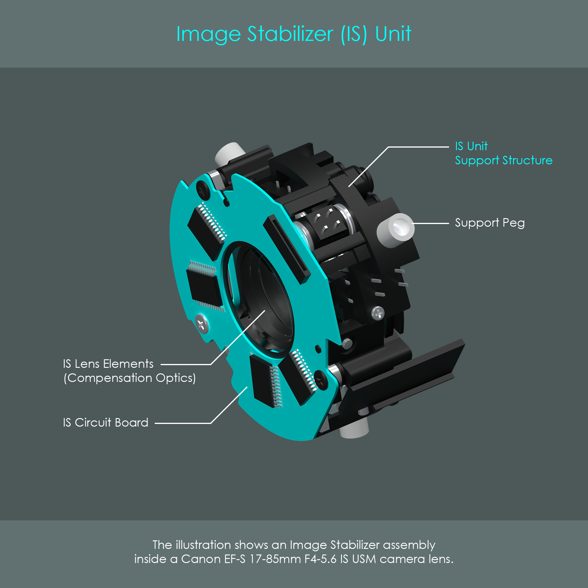
This is the support structure for all optical, mechanical and electrical components that are integrated into the unit. The support structure is mounted into the lens barrel so that the compensating optics are positioned at their intended location within the optical path. In this example, the IS unit is part of the zoom assembly where the unit has to move axially when the focal length is changed. Therefore, the unit has three nylon support pegs that are used to link the element to the helical zoom barrel.
The image stabilizer has an own circuit board with some application-specific integrated circuits on it. A connector terminal accepts a flex cable that leads to all the electrical components of the unit. An insulation sheet is put between the circuit board and the underlying metal yoke to prevent short circuits from disabling the IS system.
An exploded view of the IS unit reveals some more details.
The IS lens cell is the shifting part that houses the compensation optics. Canon's stabilized lenses have between one and four optical elements integrated as compensation optics. In case of the Canon EF-S 17-85 F4-5.6 there are two optical elements (L12 and L13) to compensate shaking. Depending on the optical design, compensation optics can also be installed in the front part in the lens. A guide axis prevents the IS lens cell from performing unwanted movements such as tilting or rotating. Instead, the IS lens cell is supposed to move only vertically and diagonally. If not actuated, the IS lens cell rests in a zero position where the optical axis passes through the center of the compensation optics.
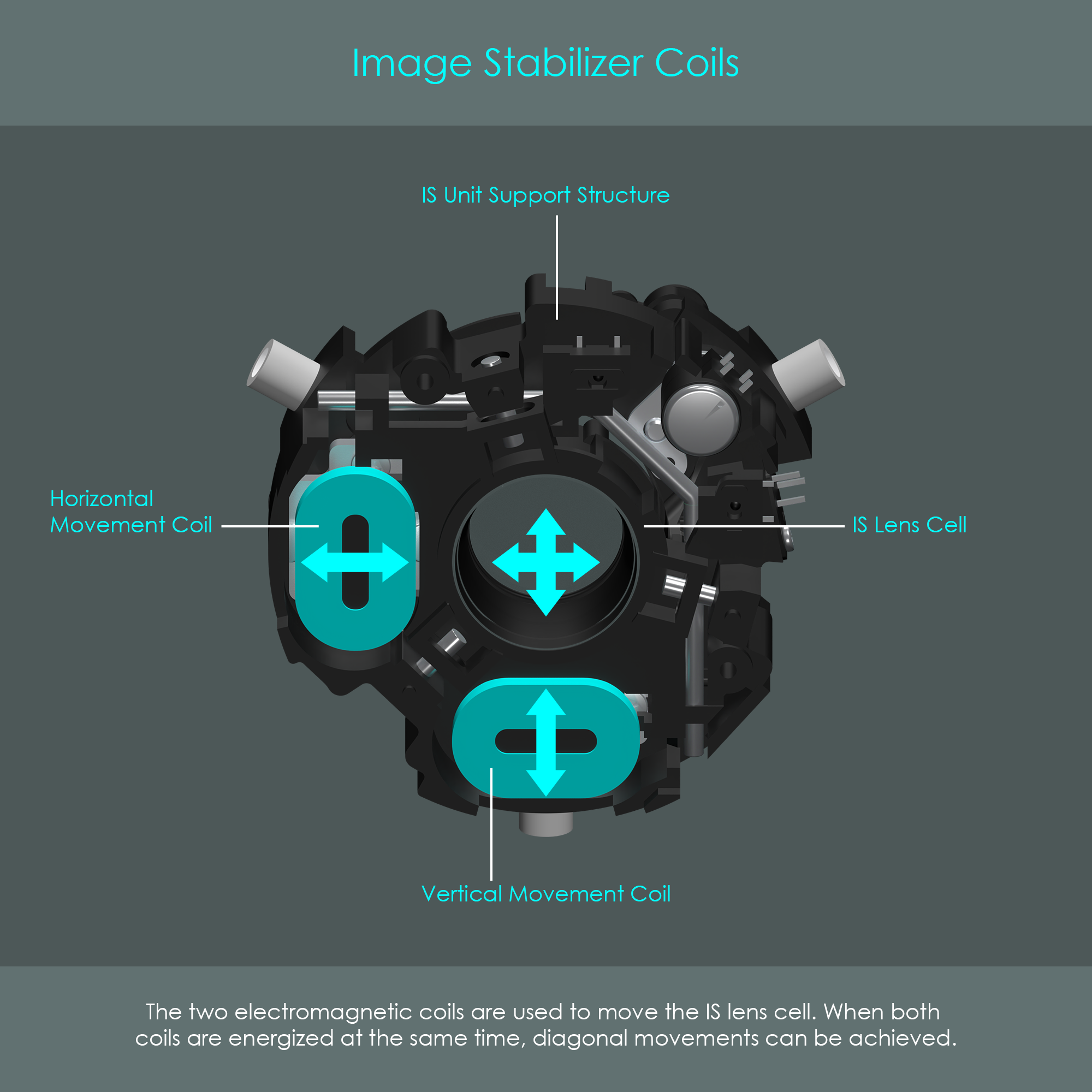
The IS lens cell is moved by magnetic force. To control the direction and intensity of the movement, the IS unit uses both permanent magnets and electromagnets. The basic principle is that opposite magnetic polarities attract each other whereas identical magnetic polarities repel each other.
The IS uses a feedback system that reads the position of the IS lens cell. This feedback system consists of two infrared emitting diodes (IRED) and two position sensitive detectors (PSD). The IREDs are mounted to the shifting IS lens cell whereas the PSDs are mounted to the underside of the stationary IS circuit board. As soon as the image stabilizer turns on, both IREDs emit infrared light directed towards the PSDs. These PSDs are designed for one-dimensional displacement metering and they have a long and narrow photosensitive area to detect light in a longitudinal direction. One PSD detects displacements horizontally and the other one vertically, and both signals are processed by integrated circuits on the IS circuit board. This position feedback is used to fine-tune the stabilizing movements of the IS lens cell.
The exploded view of the IS unit reveals another lens cell that holds optical element L14. This optical element does not play any role in the compensation of shaking and vibrations but instead is a regular lens inside the optical path. The overall lens design allowed it to attach L14 to the same support structure than the IS optics, mainly because L12 - L14 are all close to each other and they perform an identical axial displacement when zooming the lens. A particular feature of L14's lens cell is the attachment via three eccentric screws that are used to correct for slight imperfections in the lenses image position. The eccentric lens cell is held in place by a dedicated metal bracket screwed to the IS unit support structure. The eccentric screws are used to fine-tune the horizontal and vertical position of L14.
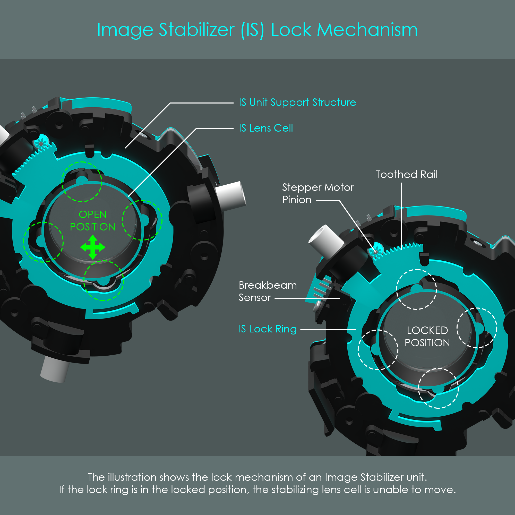
The IS unit is able to lock and unlock the shifting lens cell depending on the IS switch position on the lens barrel. Mechanically locking the compensation optics prevents the lens from unintentional shifts when stabilization is turned off.
The IS lock mechanism consists of a lock ring and a stepper motor for turning the ring. The lock ring is held at the back of the IS unit support structure by several brackets so that it is free to turn. The lock ring has two protrusions on the outer diameter, one has a toothed rail on the edge and the other is a barrier to slide through the break beam sensor for position sensing. On the inner diameter, there are four indentations that give the IS lens cell some freedom of movement once the ring is in the unlocked position. However, once the lock ring is turned to the right, the IS lens cell is locked in place with no more space to move. The ring is turned by a stepper motor mounted to the front of the IS unit support structure. The shaft of the stepper motor reaches through the support structure and a tiny pinion engages with the toothed rail, driving the lock ring in the desired direction.
Shaking and vibration is detected by two specialized sensors, one to detect horizontal vibrations and the other to detect vertical vibrations.
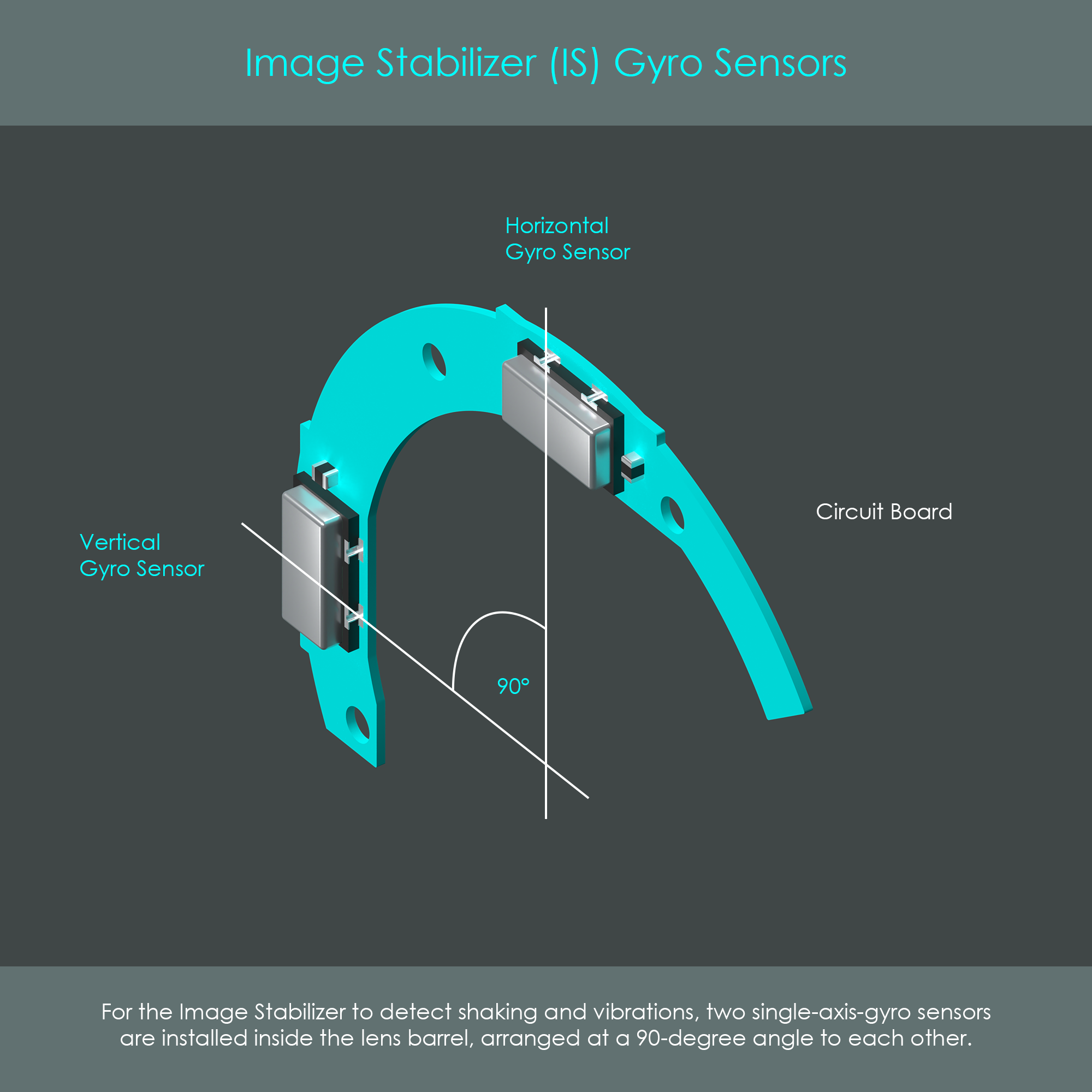
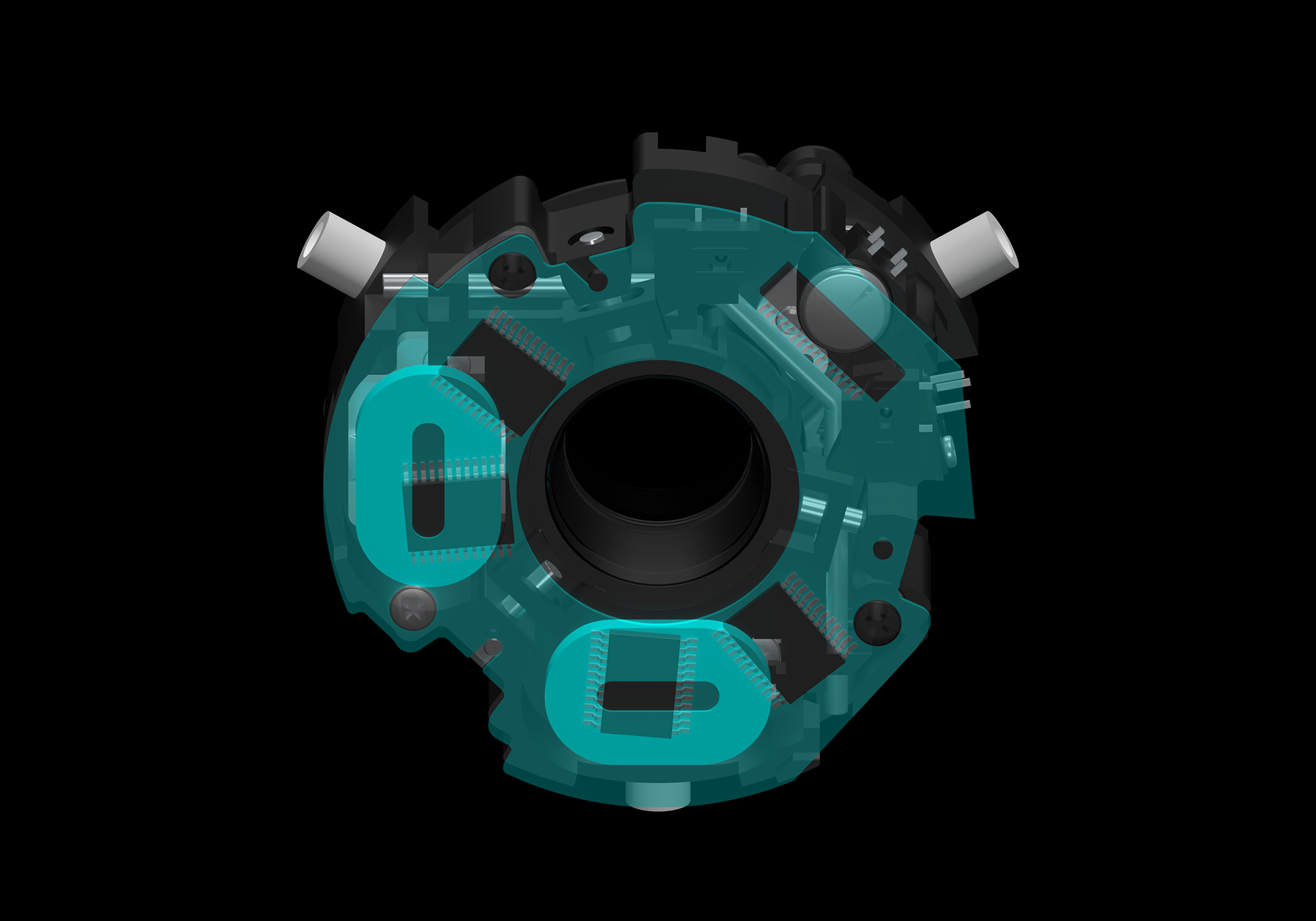
The scientific name of these vibration-detecting devices is piezoelectric angular velocity sensors, gyroscopic sensors, or gyro sensors. Every image stabilized Canon lens has two of these gyro sensors embedded inside the barrel. The two sensors are arranged at a 90-degree angle to each other. Depending on the lens design, they may be mounted on a semi-circular piece of circuit board or flex cable which is attached to an inner barrel.
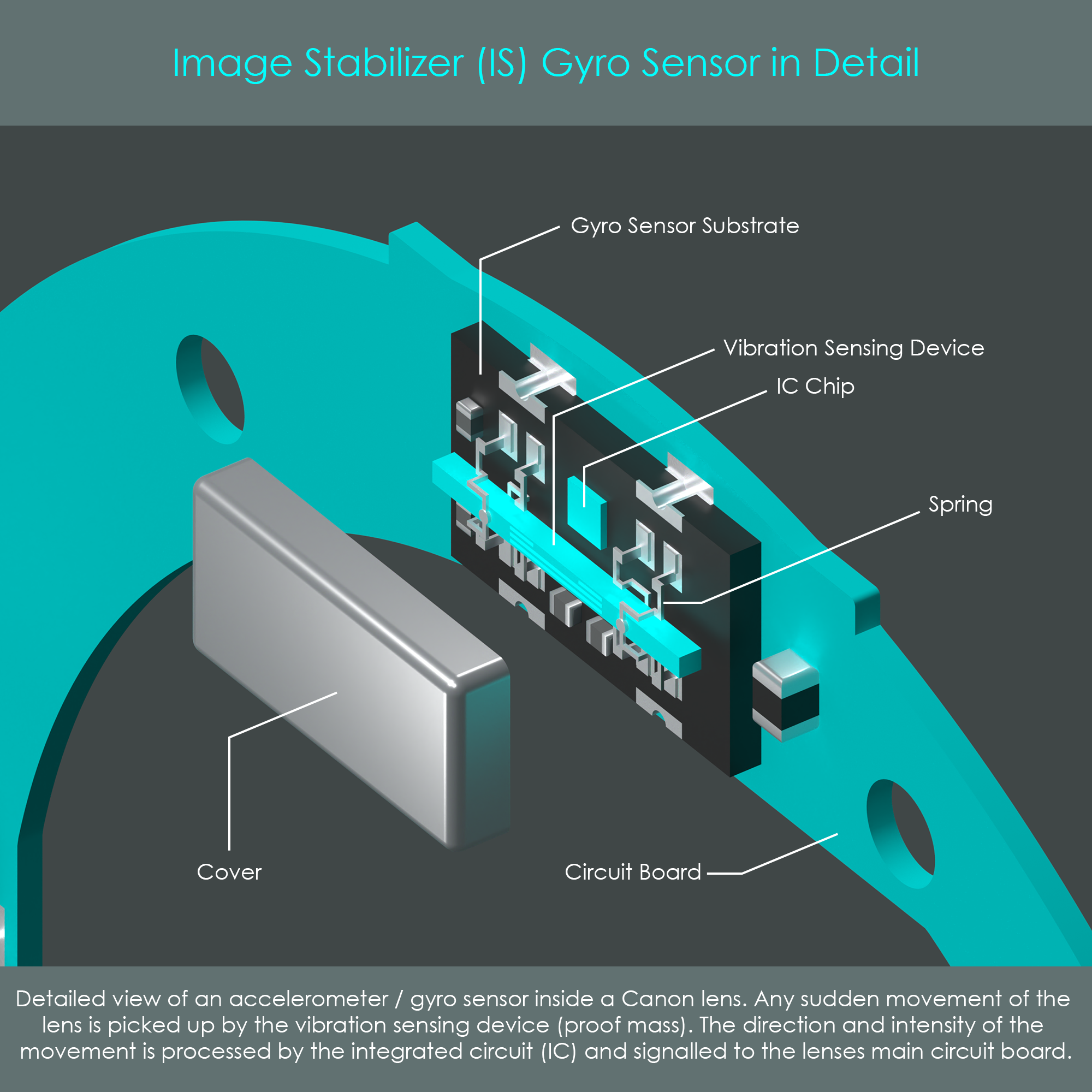
On the inside of a gyro sensor, a piezoelectric vibration sensing device – also referred to as proof mass – is suspended from conductive metal springs. In the presence of vibration or shaking, inertia deflects the sensing device from its zero position, and an increase in resistance can be measured by the integrated circuit (IC) chip that is embedded into the unit. The IC communicates the direction and intensity of vibration to the lenses main circuit board, where this information is forwarded to the IS unit for compensation. A metal cover protects the gyro sensor's inside from physical damage and from environmental attack.