Today's photographic lenses rely on numerous electronic components such as switches, sensors, autofocus actuators, electromagnetic coils for image stabilization, and more. All these components are connected to a central lens mainboard which in turn is connected to the camera. This chapter explains how the lens communicates with all its electronic components, and with the camera.
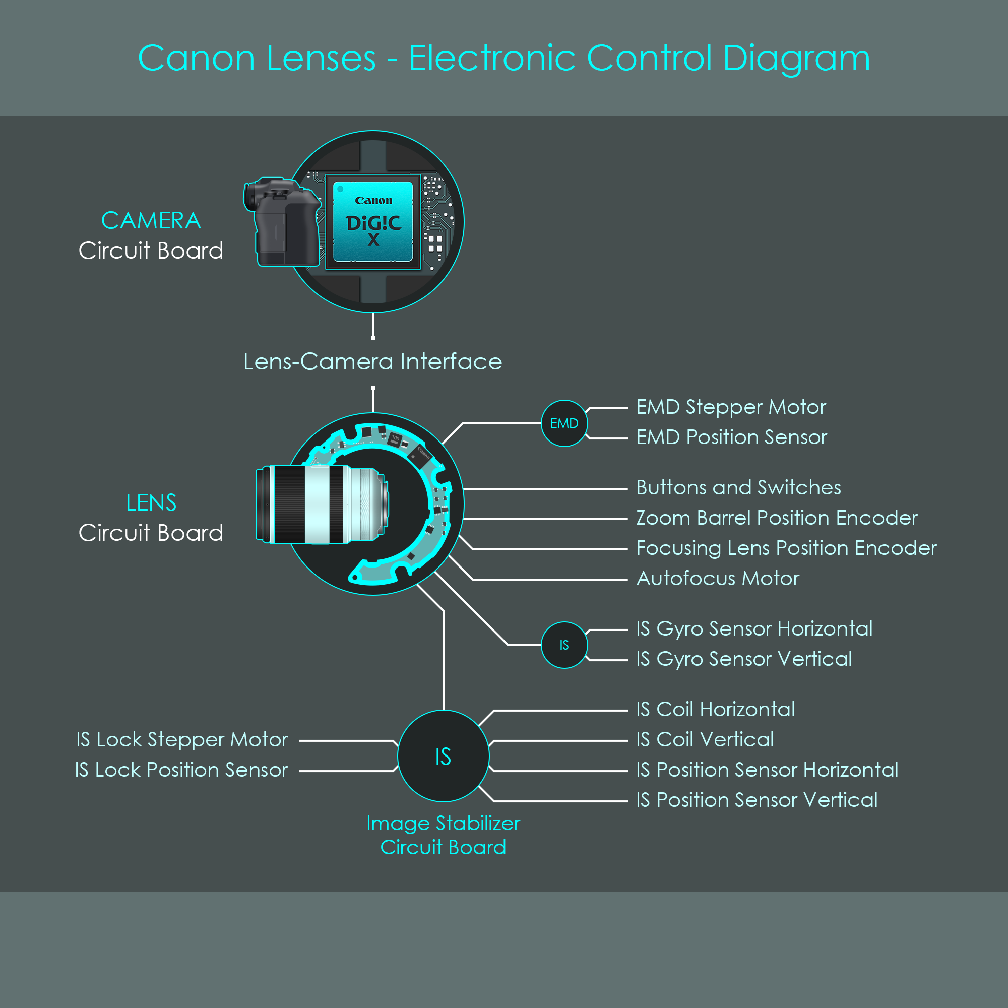
With the Canon EOS, EOS M and EOS R camera systems, the the lens and the camera communicate with each other. For example, when the camera controls are set to a certain f-stop value, this value gets processed by the camera's main processor. Canon EOS R cameras rely on the DIGIC X digital signal processing unit, a powerful integrated circuit that controls all camera functions but also exchanges information with the lens. The camera translates any required f-stop value into a number of bits, and transfers them to the circuitry of the lens. Inside the lens, that information about the f-stop value is read by the lens CPU which calculates the number of turns the EMD motor has to perform for the diaphragm blades to have the correct aperture size. Once the camera's shutter button is pressed, the lens issues a signal to the EMD motor controllers which in turn generate pulses to excite the EMD stepper motor. There is another data line that is used to transmit signals back to the camera. These return signals may include general lens type information, switch positions, status flags but also error codes in case of malfunctions.
In modern camera systems, virtually all communication relies on digital signal processing. Small microchips such as the lenses CPU use digital signals to exchange information with other circuits inside the camera and the lens. Motor drivers inside the lens are controlled via digital inputs. Electromagnetic coils inside stepper motors are energized via digital pulses. Lens position encoders are read out via digital circuits as well. In some cases, signals generated by sensors may be analog, but these are often immediately converted into a digital signal that is processed by integrated circuits.
If a circuit is designed to process digital signals, all information is represented either by low voltage (usually zero volts) or high voltage (usually the supply voltage of the system, often between 3 and 6 volts). This is also called a binary signal, and the two voltage levels correspond to the two values '0' (low voltage) and '1' (high voltage). So at any given time, a binary signal represents one binary digit (bit). If you want to read more about digital signal processing, here is an e-book about microchips and digital signal processing.
To transfer information between digital systems, multiple bits can be sent via bus systems. A parallel bus consists of multiple wire channels that can be used to transfer multiple bits at the same time. By contrast, a serial bus consists of a single channel where data is transmitted one bit after the other. Either way, protocols are integrated into both sending and receiving circuits to control transmission rates and timing, and to ensure error-free data exchange.
The electronic interface of Canon's lens mount system consists of spring-tensioned metal pins on the camera-side and metal contact pads on the lens side. Once a lens is attached to a camera and turned into its locked position, all pins engage with the corresponding pads and establish an electrical connection.
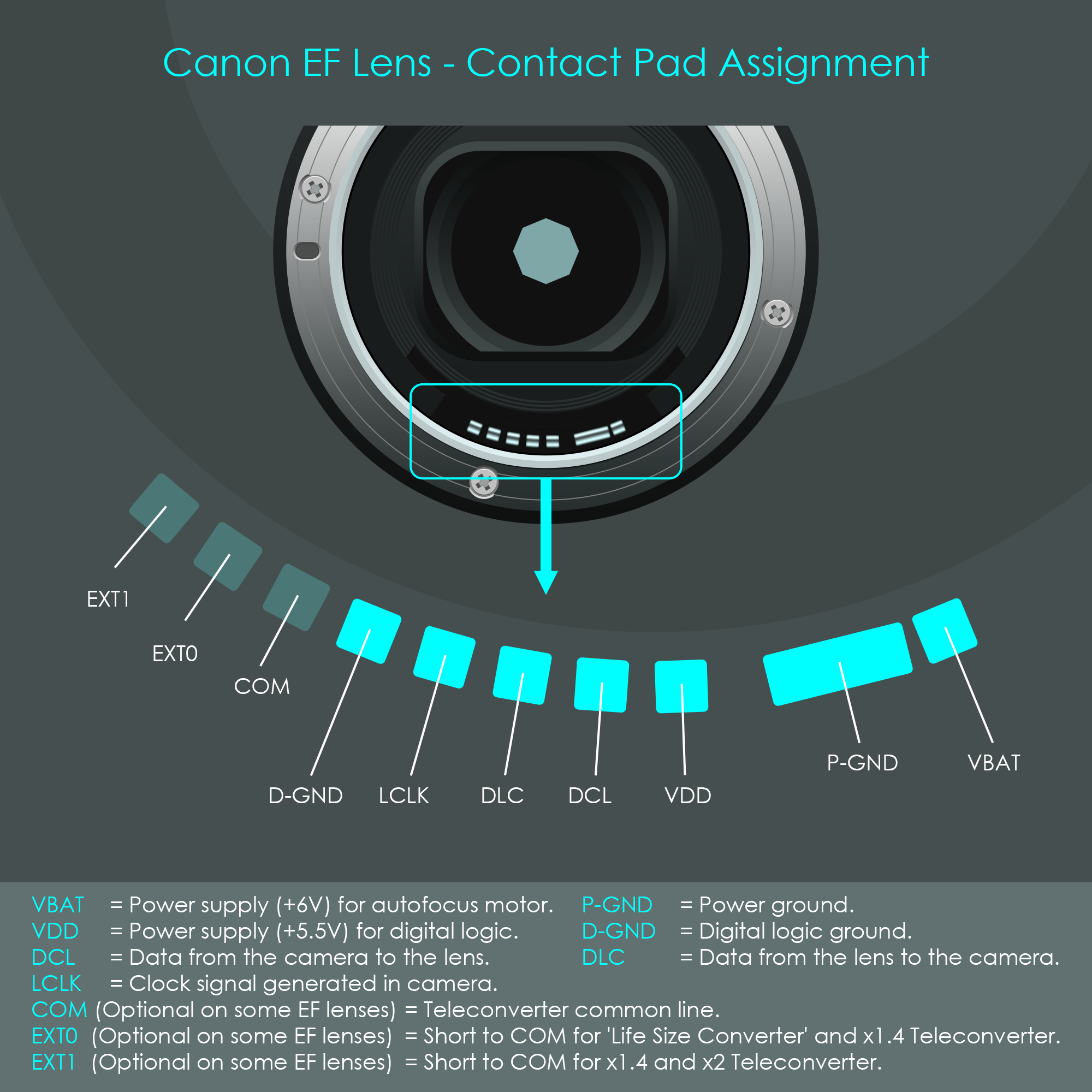
Canon's EF mount has an eight-pad connection (P-GND counts as two). Three more pads can only be found on most L-lenses and macro lenses. The RF mount has a 12-pad connection between the camera and lens. This provides greater bandwidth for data transfer, and also faster communication between lens and camera.
Some of the connectors provide power to the lens while others establish data connections. All Canon lenses compatible with EOS, EOS M and EOS R camera systems have their own circuit board and microprocessor integrated. This dedicated circuitry is used to control autofocus, aperture, image stabilization and to read sensors (gyro sensors to detect lens shaking, focus-by-wire position sensors, etc.) as well as zoom positions.
The illustration of Canon's EF lens contact pad assignment shows that there are actually two separate power rails used by the camera to supply two voltages to the lens. Contacts labelled VBAT and P-GND provide +6 volts to the lens which is used for the internal autofocus motor and image stabilizer coils. Contacts labelled VDD and D-GND provide +5.5 volts which is used to power all digital logic circuits like the lens CPU and other integrated circuits. LCLK is an electrical contact through which the camera provides a 77 kHz clock signal that is also required to drive the digital logic part of the lens electronics. This reduces complexity as the lens doesn't require an own clock generator, and ensures that both camera and lens electronics are perfectly synchronized.
In their EOS, EOS M and EOS R camera systems, Canon uses two data lines to communicate with the lens. One line is referred to as DCL (data from camera to lens) and another line is referred to as DLC (data from lens to camera).
DCL (data from camera to lens) is used by the camera to send commands to the lens, for example 'change aperture' followed by an 'increase' or 'decrease' bit and a binary number that defines the amount of change. DLC (data from lens to camera) is used by the lens to respond to a command starting on the next clock cycle. A typical case is where the camera sends the command 'get lens name' through DCL and the lens responds with its model name through DLC. This information is then saved in the EXIF data of digital image files.
Both lines run a serial peripheral interface (SPI) protocol to exchange information between the lens and the camera. For the SPI protocol to work, one unit must be defined to control the other, and that relationship is usually expressed by the terms master and slave. The master controls the slave (or multiple slaves). Canon has designed the camera to be the master and the lens to be the slave.
The signals that run through the DCL data line can also be expressed as MOSI (master output, slave input). Consistently, the signals that run through the DLC data line can also be expressed as MISO (master input, slave output)
The SPI protocol itself uses eight data bits and one stop bit to transmit information. Once a command has been issued via the SPI protocol, the lens responds with an answer that can have between one and seven bytes (one byte is eight bits).
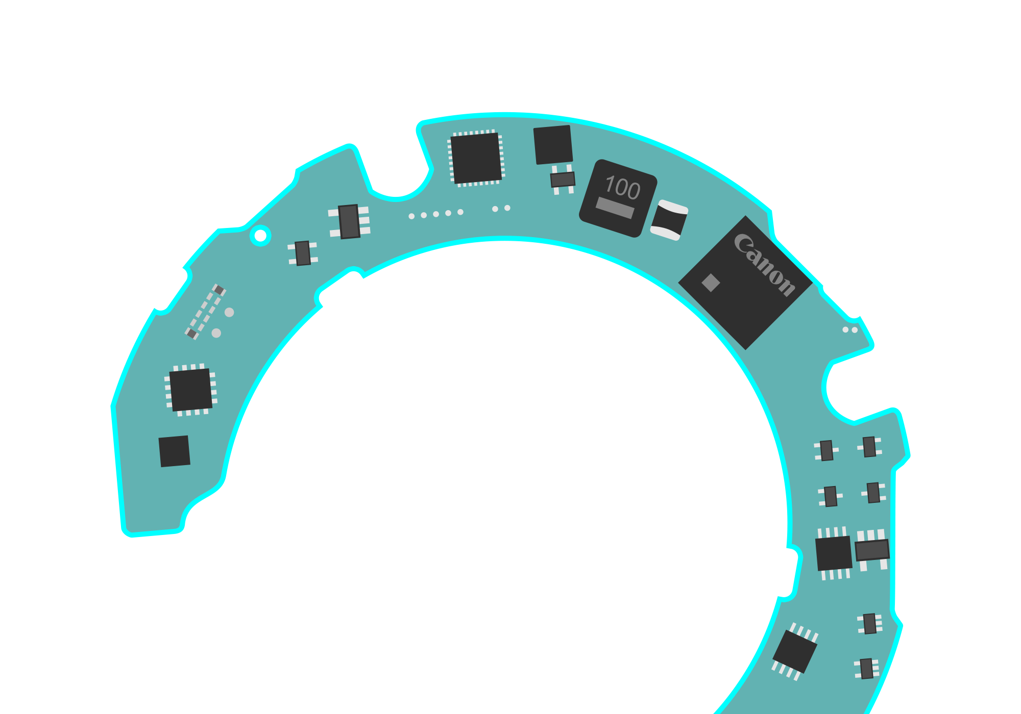
The largest part of all electronic components inside Canon's EF (including EF-S) and RF (including RF-S) lenses is installed on a single printed circuit board (PCB). To prevent this circuit board from blocking any light, it is normally designed in a ring shape. Canon's lenses have their PCBs typically installed at the back of the lens barrel directly next to the lens mount.
The structure of a lens circuit board is complex: Due to space limitations, the circuit board is populated with components on both sides (double-sided PCB). Copper wire traces establish electrical connections between individual components. To allow these electrical conductors to cross each other without touching, the printed circuit board itself consists of multiple layers of substrate material laminated together. Internal wires are sandwiched between the layers. Tiny holes – called vias – connect wire traces from the surface to the buried traces inside the stack of layers, or all the way through to wire traces on the opposite surface.
Electronic components are soldered to the PCB by using surface-mount technology. The components used for this technology are referred to as surface-mount devices (SMD). These are particularly small compared to through-hole components which makes them ideally suited for this tight space.
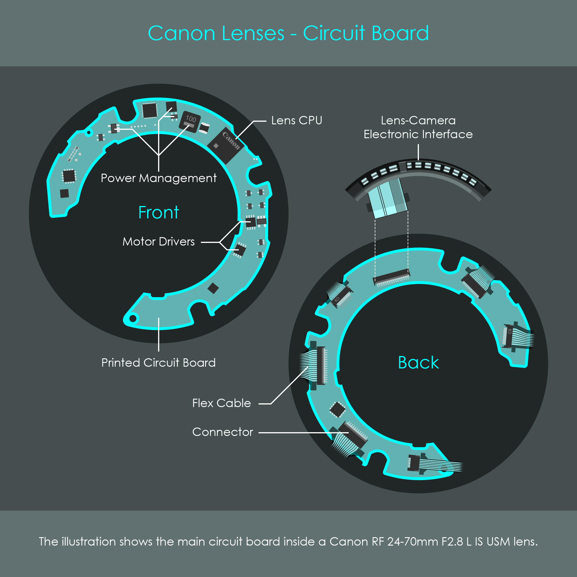
The front of the PCB (facing the front of the lens) is typically populated with components such as power management devices, the lens CPU, as well as other microcontrollers and components.
The back of the PCB (facing the lens mount) is occupied by the flex cable connectors. Canon uses flex cables to connect all of the electrical units inside the lens with the PCB. The illustration shows the circuit board inside a Canon RF 24-70mm F2.8 L IS USM zoom lens, including front and back. The flex cable connectors are usually facing the back of the lens because the PCB is one of the last units installed when the camera lens is assembled. The PCB is screwed onto its support area inside the lens barrel, and then the flex cables get slid into their respective connector terminals. As most flex cables lead into the lens barrel, the PCB is designed to have flat indents in front of their connectors to prevent the flex cables from bending too strongly. The lens-camera interface (the actual part that is pressed against the contact pins of the camera body) connects to the PCB in a similar way using a flex cable. Instead of leading into the lens barrel, this flex cable bends towards the interface unit which is directly next to the board. This is why that particular position has no flat indent in the board.