The bus is an internal communication system within an integrated circuit. It is a set of parallel electrical wires that transports information between individual registers. Numerous registers and other components typically share the same bus, and therefore it is also referred to as ‘common bus’. For each bit position within the registers the bus contains a separate wire. For instance, one wire of the bus system is exclusively used to carry information from the bit position “0” of all registers, another wire is only used by the bit position “1” etc. Naturally, it doesn’t work to carry the information of all registers at the same time. Therefore, to coordinate the communication between the registers and the bus system, additional control structures are required.
For information to be transferred from a source register to the bus, the register’s outputs have to be connected to the individual bus wires. However, if information from more than one register must be transmitted to the bus, the outputs of the source registers cannot simply be connected to the same line. This is due to the fact that the output lines of registers always have their stored values present, and connecting more than one register output to the same wire will result in a short circuit if both output signals are different from each other. As a solution to this problem, additional hardware and control signals are used to determine which source register is selected by the bus system at a particular time.
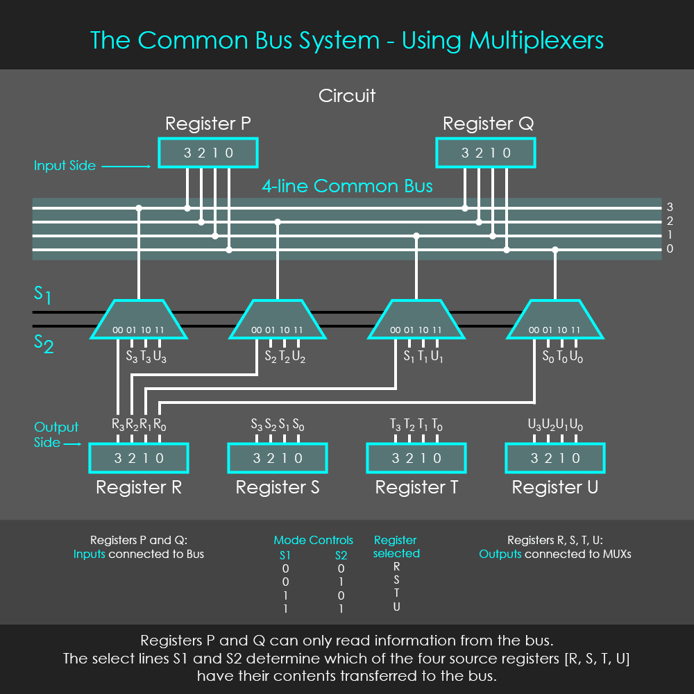
One solution to design a common bus system is to use multiplexers. These are installed in a configuration that is shown in the diagram. To connect source registers with four bits to a common bus system, four multiplexers are required. A specific control signal is applied to all multiplexers simultaneously so that all of them select the same input channel at the same time. The content of the selected register is then placed on the bus. In other words, the selected register writes its content onto the common bus.
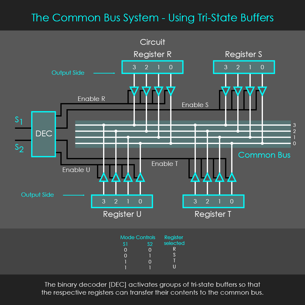
Alternatively, a common bus system can also be designed with tri-state buffers. A tri-state buffer (also referred to as tri-state gate, tri-state driver, or bus driver) is a type of logic gate that can have three output states: 1, 0 or a high impedance state, called Hi-Z, which behaves like an open switch. When the tri-state buffer is activated, it passes the input’s signal unchanged to the output. In an active-high tri-state buffer, a high control signal is required to enable the transmission of information. In contrast, an active-low tri-state buffer requires a low control signal to enable the transmission of information. The diagram shows the symbol and truth table of an active-high tri-state buffer.
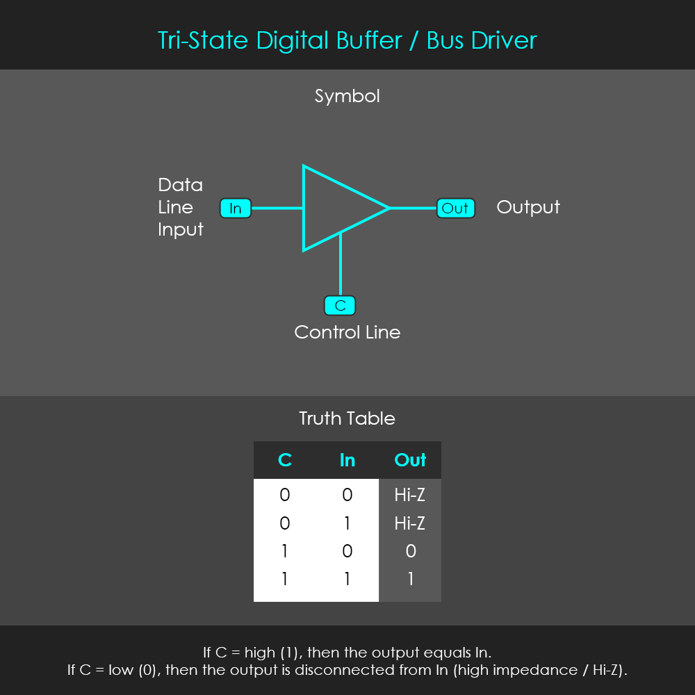
The tri-state buffer has a control input ‘C’ that turns the high impedance state on or off. If C is high (1), then the high impedance state is off and the output equals the input. If C is low (0), then the high impedance state is on and the output is disconnected from the input. More precisely, while the gate is in the Hi-Z state the output is ‘floating’ which means it is neither connected to VDD nor to GND, and therefore the output voltage is neither pulled to a logical high nor logical low level. This is effectively isolating the output from the rest of the circuit. This feature enables tri-state drivers to connect multiple outputs to the same signal line, as shown in the diagram.
In case that registers need to read information from the bus, their inputs can be directly connected to the bus without hardware inbetween. This is due to the fact that registers can independently turn reading off or on, which is different from their writing function where stored bits are always available at the output.