In clocked sequential logic circuits, flip flops are used to store one bit of data. With regard to the basic operating principle, a flip flop is comparable to a latch. However, the fundamental difference between the two is that a flip flop ensures that the output doesn’t change more than once during a single clock cycle. This is achieved by linking two latches in series so that the outputs of the first latch are used as the inputs of the second latch. A clock signal is used for both latches, whereas the clock signal for the second latch is inverted.
The SR flip flop that is explained here is built from two gated SR latches linked in series. This layout is also referred to as a master-slave SR flip flop where the latch on the left is the master and the latch on the right is the slave. The master latch has the inputs S and R connected to it as well as the CLK signal that is connected to its enable input. The slave latch has the master’s outputs connected to its inputs, and the inverse value of the clock is connected to its enable input. The outputs of the slave latch are the outputs of the flip flop.

The two inputs S and R are used to set and reset the flip flop respectively. The clock input is used to control both the master and slave latches. Therefore, the master latch is connected to the ‘original’ clock signal whereas the slave latch is connected to an inverted clock signal. The inversion of the clock signal is what actually prevents the flip flop from becoming transparent: When the clock signal turns high (rising edge), the master latch turns on and stays active during the high phase. In this phase the master latch is sensitive for inputs and stores the corresponding output. During that time, the slave latch is disabled as the inversion of the high phase is a low phase, so the enable input is low. When the clock signal turns low again (falling edge), the master latch gets disabled and stays closed during the low phase. In this condition, any signals at the R and S inputs are ignored by the master latch. However, the master latch has still stored the output that was produced during the high phase. With the clock signal low, the inversion of that low phase is a high phase at the slave latch. This in turn activates the slave, and the outputs of the master latch (which are the inputs of the slave latch) now pass through the slave latch and produce the outputs of the flip flop.
This shows that it requires one rising edge of the clock signal to pass the input signals halfway through the flip flop, and one subsequent falling edge to make the final output available at the flip flops output terminals. As long as no changes are made to the input signals of the flip flop, the slave latch stores the last outputs, even if the clock continues to run. As all the changes within a flip flop typically are synchronized to the rising and falling edges of the clock, flip flops are also called edge-triggered devices.
The symbol of a flip flop is simply a rectangular box with inputs and output lines. The clock input is often represented as a small triangle where the clock line connects to the box. Note that the arrangement of inputs and outputs can be used arbitrarily, for instance the clock input does not have to be in the center of the box.
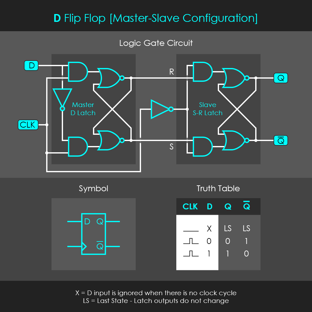
The D flip flop that is explained here is built from a gated D latch and an SR latch linked in series. An alternative design is to connect two D latches in series where the Q output of the first latch is used as the D input of the second latch. In this alternative design, the Q-Inverted outputs can be ignored.
The D flip flop bases on the same principle as the SR flip flop. The master D latch turns on at the rising edge of the clock signal and stores an output in accordance with the input D that is provided during the high phase of the clock. On the falling edge of the clock signal, the D latch disables and ignores further input signals. In turn, the inverted clock signal activates the slave SR latch which stores an output in accordance with the master latch outputs.
For some practical applications of flip flops, it is sometimes required to have preset and reset inputs. A high signal at the preset input sets the D flip flop’s output high without any other input requirements (no high signal at the data input and no clock cycle required). A high signal at the reset input sets the D flip flop’s output low without any other input requirements. The following circuit shows that this ‘override’ effect is achieved by directly connecting the preset (PRE) and reset (RES) inputs to three input NOR gates of the slave latch.
Similar to a latch, a flip flop only keeps its memory as long as power is connected to the device. Whenever the power supply is disconnected, the stored bit of data is lost. For long-term memory, other devices are used, which are outside the scope of this article.
