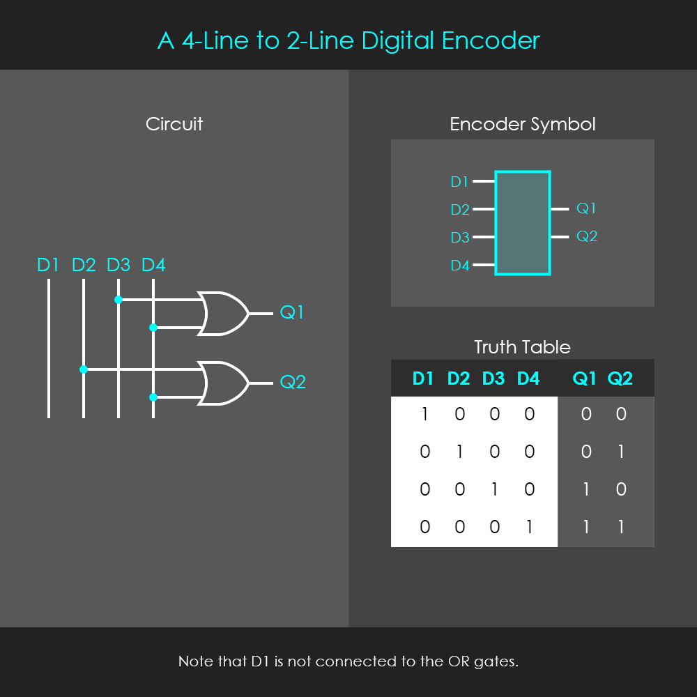
Encoders and decoders are both combinational circuits. An encoder performs a conversion of an input with two to the power of n lines into an n-bit binary code at the output. On the opposite, a decoder performs a conversion of an n-bit binary code into two to the power of n unique outputs.
The circuit shown here is a 4-to-2-line encoder, and it performs a one-hot to binary conversion. One-hot means that the format of the input lines only allows one unique line to be high (‘hot wire’) at a time. So there is a total of four input combinations (1000, 0100, 0010, 0001) that can be converted into 2 bits of binary code. The circuit is not designed for other input combinations.
Encoders are very useful circuits for various reasons. Encoding can be used to minimize the number of data lines required for signal transmission. A particularly useful application for encoding is the translation of input devices into binary code. For instance, pocket calculators use encoders to translate the decimal numbers of their keypad into binary numbers so that they can be used for further operations. Also, computer keyboards use encoders to convert their alphanumeric keys into binary code that can be processed by the computer.
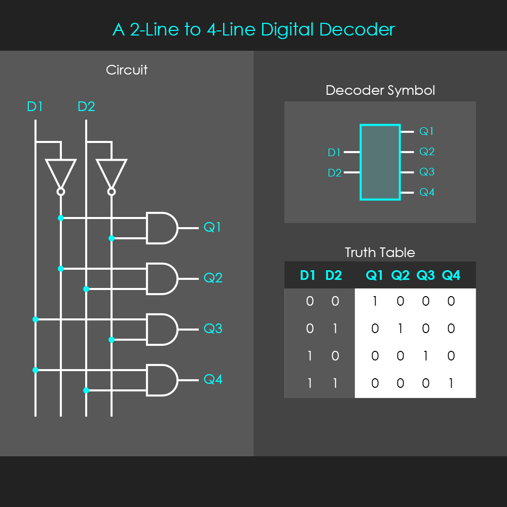
The decoder shown in the diagram is a 2-to-4-line decoder, and it translates 2 bits of binary code into a distinct output signal. The output signal of this decoder circuit again is in a one-hot format, and therefore only one of the four output lines can be high at a time.
Decoders have a number of useful applications. Their one-hot output signals can serve as enable signals for functional units (instruction decoding). In memory circuits they can also be used to enable different banks of memory, so in this application the inputs of decoders effectively become address lines. When a continuous counter is connected to their input lines, decoders can also be used as sequencers to turn various devices off or on in a repetitive and sequential way.