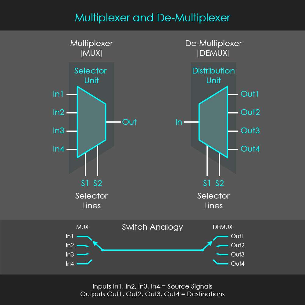
A very common use of combinational logic is in multiplexers and demultiplexers. A multiplexer (MUX) is a circuit that accepts multiple data inputs and has one single output. The circuit itself serves as a selector that establishes a connection between one of the inputs and the output depending on the signals provided by the selector lines. Each multiplexer has two to the power of n inputs, and n selector lines. Therefore, a multiplexer performs a parallel to serial conversion. Very common multiplexer types are 2:1 (1 selector line), 4:1 (2 selector lines), 8:1 (3 selector lines), or 16:1 (4 selector lines), but there are also types with more inputs.
A demultiplexer (DEMUX), on the other hand, is a circuit that has one single input and multiple outputs. The circuit is a distributor that establishes a connection between the input and one of the outputs depending on the signals provided by the selector lines. Therefore, a demultiplexer performs a serial to parallel conversion. Demultiplexers are literally reversed multiplexers, and therefore the same applies for their numbers of selector lines and outputs. They have two to the power of n outputs, and very common types of demultiplexers are 1:2 (1 selector line), 1:4 (2 selector lines), 1:8 (3 selector lines), 1:16 (4 selector lines), but there are also types with more outputs.
Multiplexers and demultiplexers are often used in communication systems to carry multiple data signals using a single line for transmission. Implementing a single transmission line is reducing cost if larger distances need to be overcome. In digital integrated circuits, multiplexers are often used as input selectors to control which data line is connected to an input of a specific unit. The figure shows the symbols for both MUX and DEMUX units.
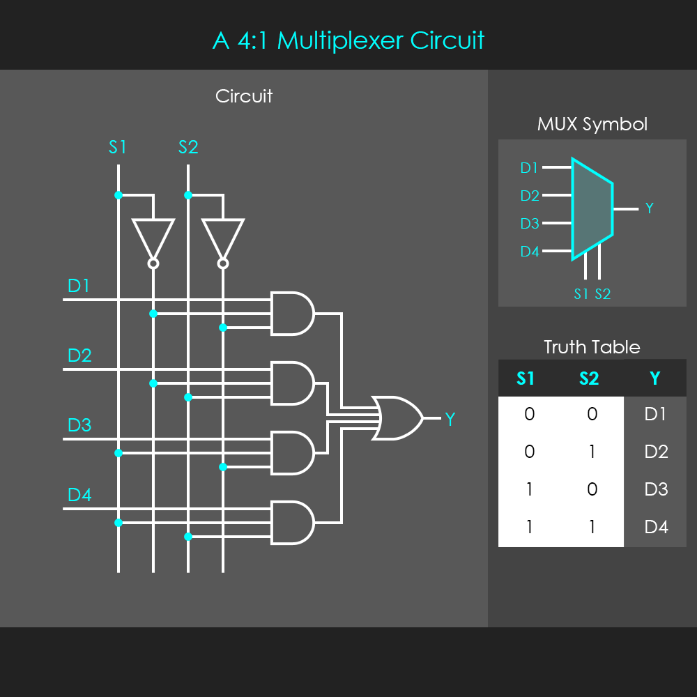
The circuit of a 4:1 multiplexer consists of four three-input AND gates, and a four-input OR gate. Each selector line is split up into two branches, one of those is the ‘original’ selector signal, and the other leads through an inverter, and is therefore the inverted selector signal. Each of the inputs occupies one of the inputs at the AND gates. The remaining two inputs of the gates are connected to the split-up selector lines as shown in the diagram.
It is worth recalling the basic principle of a three-input AND gate: The output of a three-input AND gate is only high (1) when all of the inputs are high (1) at the same time. As long as one of the inputs is low (0), the output is always low (0). Whenever two of the inputs are high (1), the output is always equivalent to the third input.
Looking at the top AND gate, if a signal at D1 should be forwarded to the output Y, the two lower inputs of that top AND gate need to be high (1). The circuit diagram shows that these lower inputs are connected to the inverted branches of the selector lines, and therefore the two lower inputs of that gate are only high (1) if both the selector signals are low (0). In this condition, no other gates have both of their lower inputs high at the same time. The truth table shows that D1 is selected when S1 and S2 are both 0. The same principle applies when selecting the other inputs. For instance, the second input D2 is connected to the second AND gate that has two of its inputs connected to the inverted S1 line and the non-inverted S2 line. So any signal present at D2 is forwarded to Y only when S1 is low (0) and S2 is high (1). The output of the four-input OR gate is high whenever one of the inputs is high, so it effectively just forwards any of the AND gate outputs to the output of the multiplexer unit.
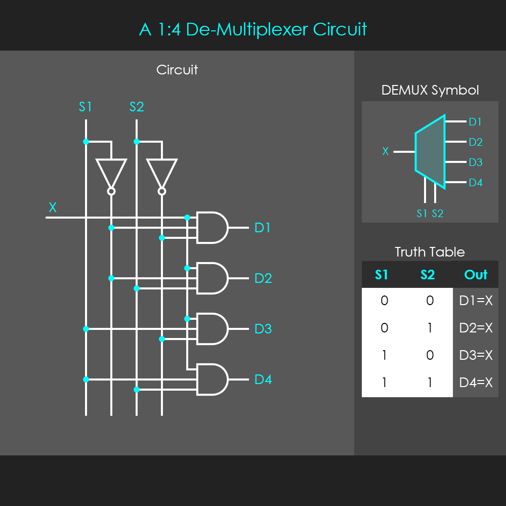
The circuit of a 1:4 demultiplexer is very similar to a multiplexer circuit. It consists of four three-input AND gates, and has its selector lines split up into non-inverted selector lines and inverted selector lines. With a demultiplexer, each output of an AND gate is an output of the demultiplexer unit. Each of the AND gates has one of their inputs connected to the single input of the demultiplexer unit.
Looking at the top AND gate again, if the input signal X should be distributed to the D1 line, both of the remaining two inputs at the top AND gate need to be high (1). This is the case only when both selector signals are low (0) because then the inverted selector signals which feed into the two gate inputs are high (1). In this condition, the output D1 follows the input X, it is high whenever X is high, and low whenever X is low. The truth table shows that D1=X when S1 and S2 are both 0. Again, the same principle applies for the distribution of the input signal to the other output lines. For instance, the input is forwarded to the D2 line only if S1 is low and S2 is high.