Photographic lenses are all about capturing light and producing images of the world. However, before diving into lens-related explanations, it is important to understand what light really is and how it behaves in combination with certain materials. This background helps to understand why the world can actually be seen or photographed.
The wave-particle duality is a physical concept that describes that light has the properties of a wave and a particle. Here is some history on how this model has developed:
The wave model of light: In 1801, the English physicist Thomas Young asserted that light has the properties of a wave. He demonstrated that in an experiment called Young’s Interference Experiment. This experiment showed that light passing through two slits (double-slit) adds together or cancels each other, forming an interference pattern on the screen further behind the slits. This phenomenon cannot be explained unless light is considered as a wave.
The particle model of light: More than a century later, in 1905, Albert Einstein succeeded in explaining the photoelectric effect. The photoelectric effect is a phenomenon where irradiating blue light on metal emits electrons from it, whereas the other colors of light are not capable of emitting any electrons from the metal no matter how long or how intense the light is applied. This effect is inexplicable if light is considered as a wave. Einstein asserted that light is a beam of particles (called photons) whose energies are related to their wavelengths. Blue light consists of photons having high energy capable of emitting electrons from the metal whereas yellow or red light consists of photons whose energy is not sufficient to knock out electrons from a metal plate. The important realization was that the energy of photons is quantized and is not delivered in a linear way.
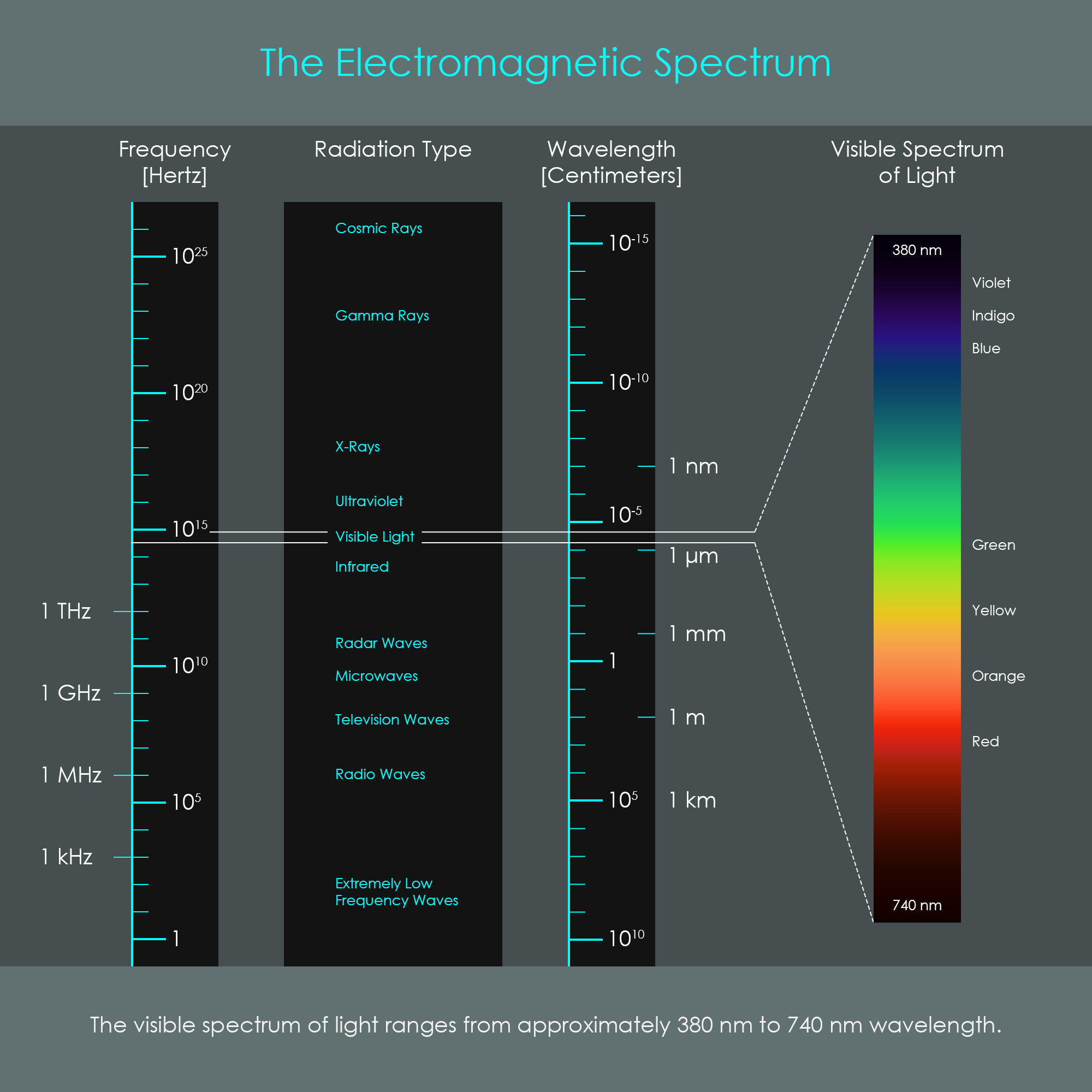
The electromagnetic spectrum describes all electromagnetic radiation from the femtometer to the high kilometer wavelength range. Most of that radiation like radio waves or X-ray is invisible to the human eye. It is only the small portion called the 'visible spectrum of light' which can be perceived by the human eye. While electronic sensors can be designed to record most of the other types of electromagnetic waves, photographic image sensors are designed to respond to the visible spectrum of light.
The list below shows some ranges of wavelengths inside the visible spectrum of light and what color they correspond to.
It is interesting to think about the following fact: We can only see (or photograph) the world because light transmits information from the surrounding objects to our eyes (or the camera sensor). And that only happens because objects are either light sources themselves or they get illuminated by the light of other light sources and they reflect it back into the surrounding. It is that emitted or reflected light that ultimately passes through our eyes (or photographic lens) to form an image on the retina (or camera's image sensor).
The information a viewer receives is the direction from where light comes from which tells the position of an object, as well as the intensity and color of light. But even more: We can often see in an image from which material an object is made of because light interacts with objects in accordance with their material and surface texture. Therefore, light from an object often allows conclusions about the materials and surface finishes of an object just by looking at reflections, highlights, or shadows.
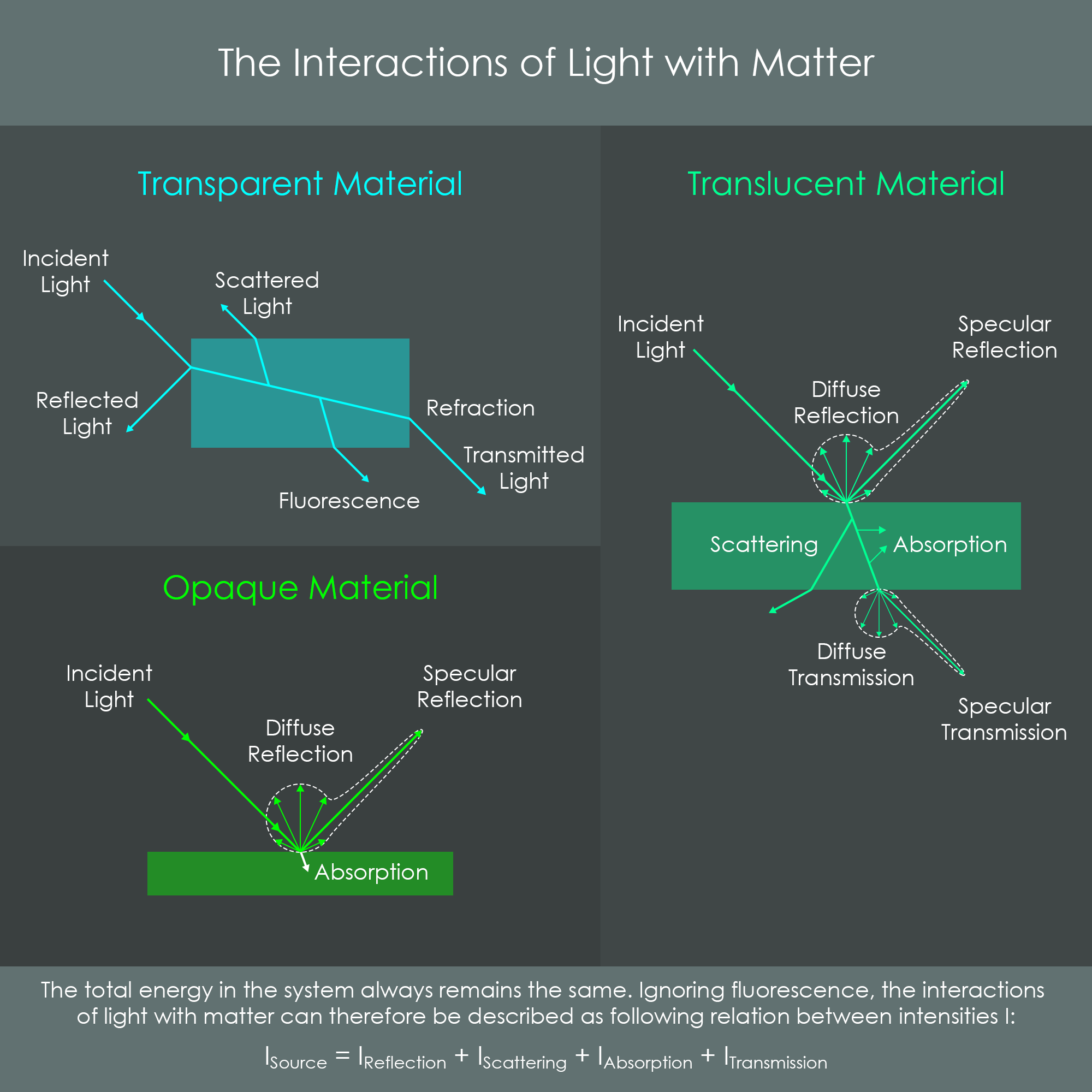
Light that is emitted from a point source always follows a linear path. However, when light hits a surface, it must interact with matter and the linear path may be redirected. There is a wide variety of possible interactions and light rarely performs just one single interaction at a time. In reality, for example, a certain material may split an incident beam of light into 70% reflected light, 20% transmitted light, and 10% absorbed light. The law of conservation of energy states that the total energy of all light rays after interactions always add up to the original energy of the incident light.
This chapter provides an overview of some basic optical principles involved in the formation of an image. Most of these concepts will be covered in greater detail in subsequent chapters.
In optical engineering it is usually a common practice to draw lens elements on an optical axis which runs through the center of all lenses. Lens elements can be imagined to be rotationally symmetric around that axis.
Another common practice is that the object space is normally located on the left side of an optical system and the image space is normally located on the right side. Therefore, incident light typically comes from the left and converges towards the right side where an image is formed. All illustrations in these series of chapters follow these conventions.
The left side of an optical system pointing towards object space is often referred to as the front, and the right side pointing towards image space (the camera's image sensor) is often referred to as the back.
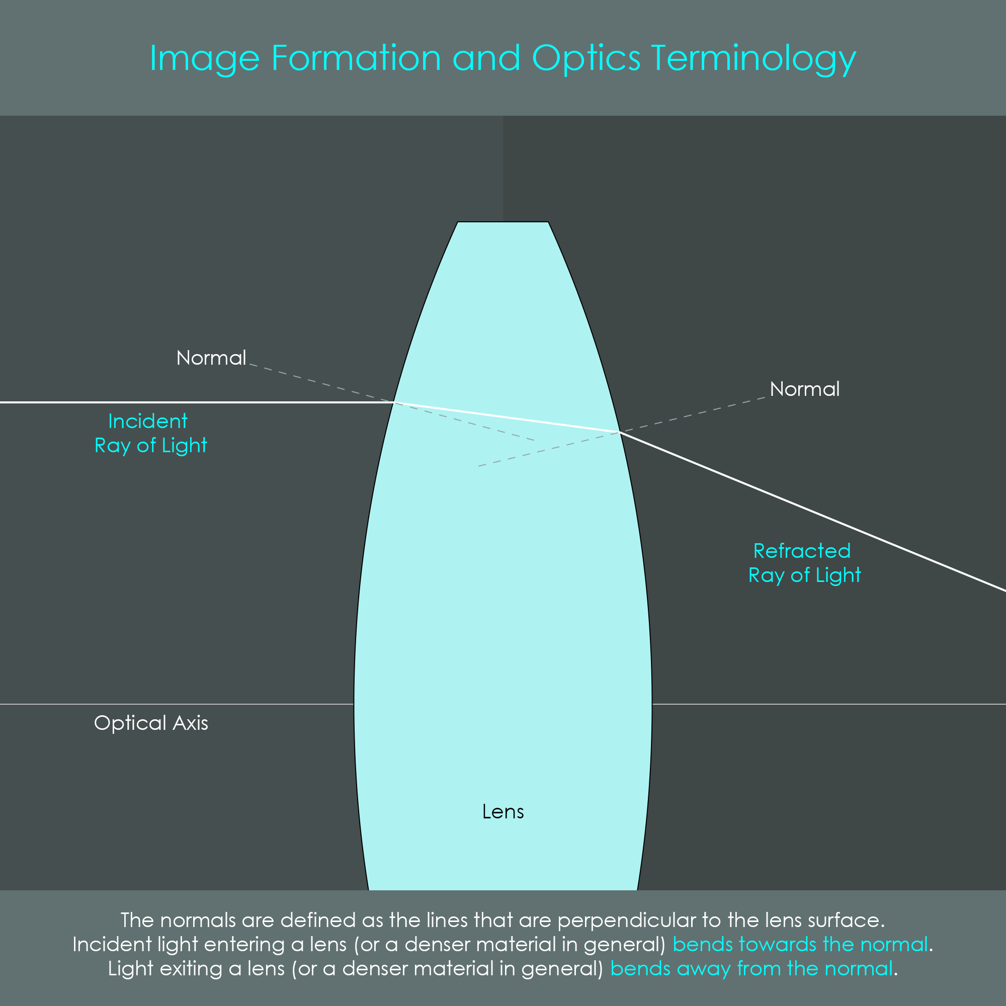
The formation of an image is based on refraction. This phenomenon occurs when light passes from one transparent material to another. A ray of light that hits the surface of a glass lens at an angle is redirected. Refraction will be explained in more detail later.
The refractive index is an optical parameter of a transparent material that determines how strong light is redirected. Vacuum has a refractive index of n = 1.0 and most glasses have refractive indices between n = 1.46 and n = 1.92.
A surface normal is an imaginary line that is perpendicular to the surface. This line helps to determine the direction in which light is refracted. In a glass lens surrounded by air, light is always refracted towards the normal when entering the lens and is refracted away from the normal when exiting the lens.
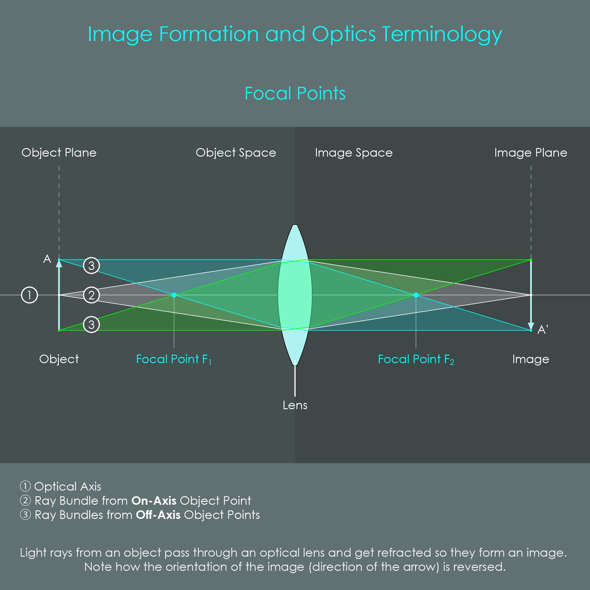
An image is a virtual reproduction of an object formed by an optical system. A bundle of light that is emitted from a single object point into the direction of the lens gets refracted and converges at a specific image point, as seen in the illustration. This occurs with all light rays from all object points. The result is an image that represents the object but is reversed.
Every Lens has two focal points. When the lens element has two convex surfaces like in the illustration, there is one focal point on each side of the lens. These focal points are very interesting geometrically: An incident ray of light that is parallel to the optical axis before passing through the lens will get refracted so that it runs through the rear focal point. Similarly, an incident ray of light that runs through the front focal point will get refracted so that it is parallel to the optical axis after passing through the lens.
If an object is located infinitely far away from the lens, incident rays of light approach almost parallel to the optical axis. In this case, an image is formed at the location of the rear focal point.
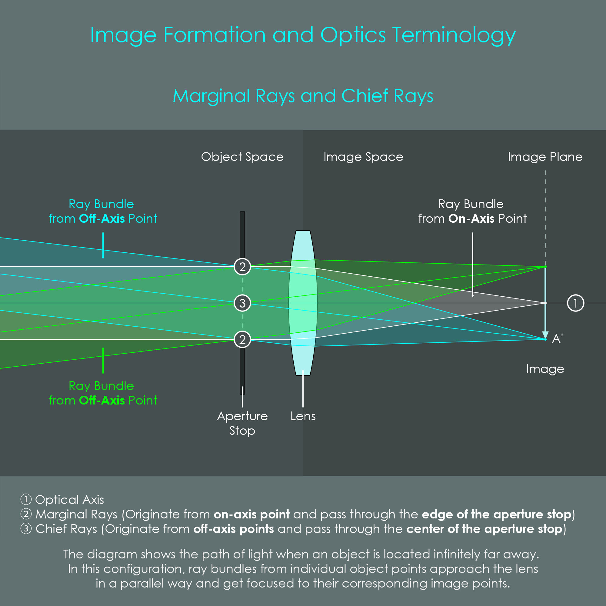
An aperture stop is an optical element that determines the maximum diameter of light bundles that pass through the optical system. It is variable in size so that a photographer can reduce the opening and therefore the diameter of the ray bundles. It is important to understand that narrowing down the fan of light rays via an aperture stop leaves the complete image intact but only reduces light flux and therefore image brightness. Stopping down can help reduce optical aberrations and image defects.
Rays of light that originate from the center of the object (on-axis object points) and pass through the edge of the aperture stop (the outermost rays in that bundle of light) are called marginal rays. Rays of light that originate from off-axis object points and pass through the center of the aperture stop are called chief rays. There is only one chief ray for every bundle of light connecting an object point with an image point.
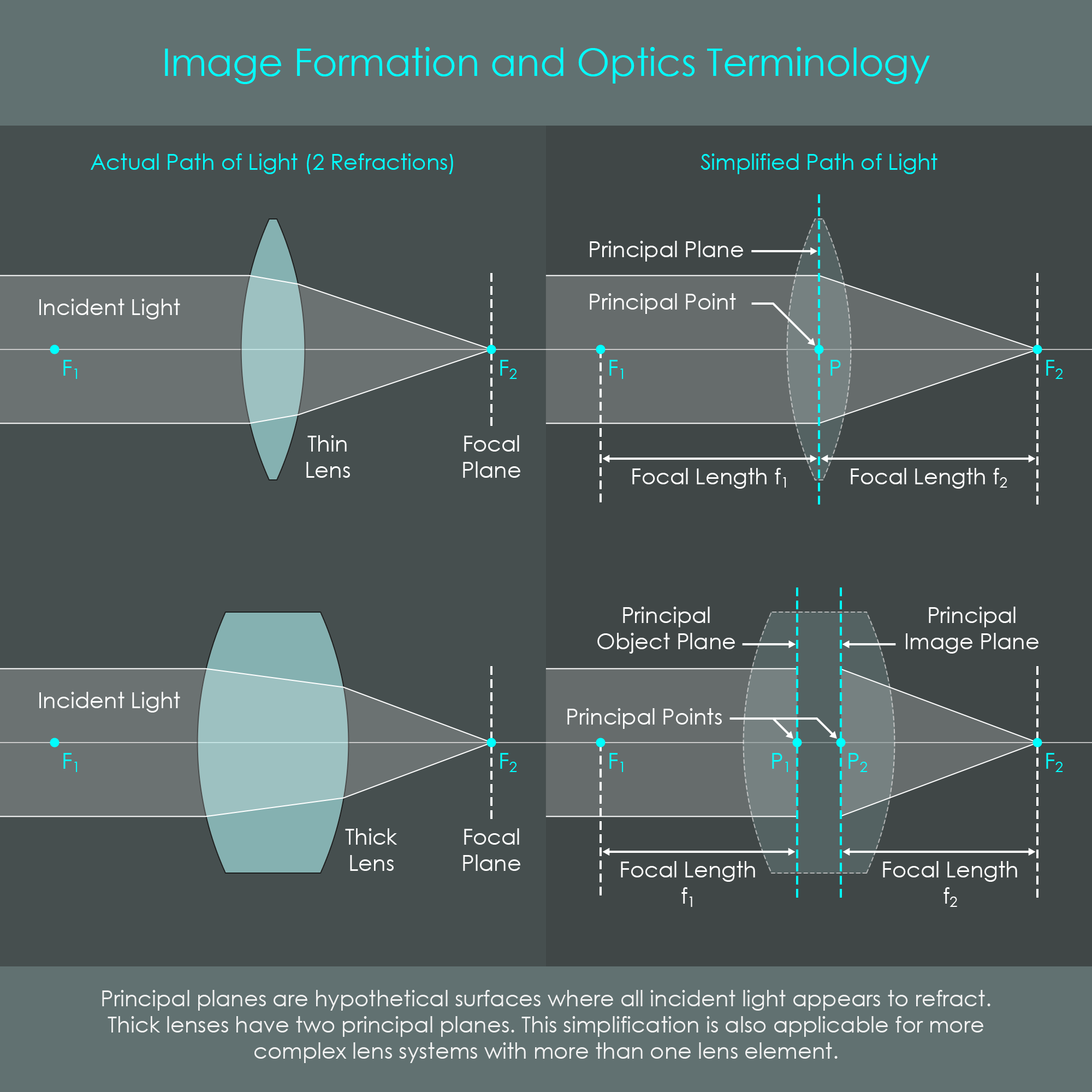
These are imaginary planes perpendicular to the optical axis. They are often used by optical designers to simplify the actual refractions that occur in an optical system. Using the simplification allows to ignore the actual lens surfaces and instead consider two principal planes to be the only surfaces where refraction occurs. Principal points are located at the intersections of principal planes with the optical axis.
The concept of principal planes is not only applicable on single lens elements but also on combinations on lenses. This is particularly helpful as the majority of camera lenses consists of a number of spaced lens elements. These complex optical systems can also be represented by two principal planes.
Every lens has two focal lengths f1 and f2, one in object space and one in image space. The focal length is the distance between the principal object point P1 and focal point F1, or between the principal image point P2 and focal point F2. Both distances f1 and f2 are of equal length.
Every photographic lens projects a circular image of the scene. The image circle must be sufficiently large to completely cover the camera's image sensor. In other words, the image circle's diameter must be equal to or larger than the sensor's diagonal. The viewing angle is determined by the individual focal length of a lens. This will be explained in more detail later. A standard lens with a focal length of 50 mm has a viewing angle of 46 degrees. The highlighted light rays form a diagonal on the image sensor.

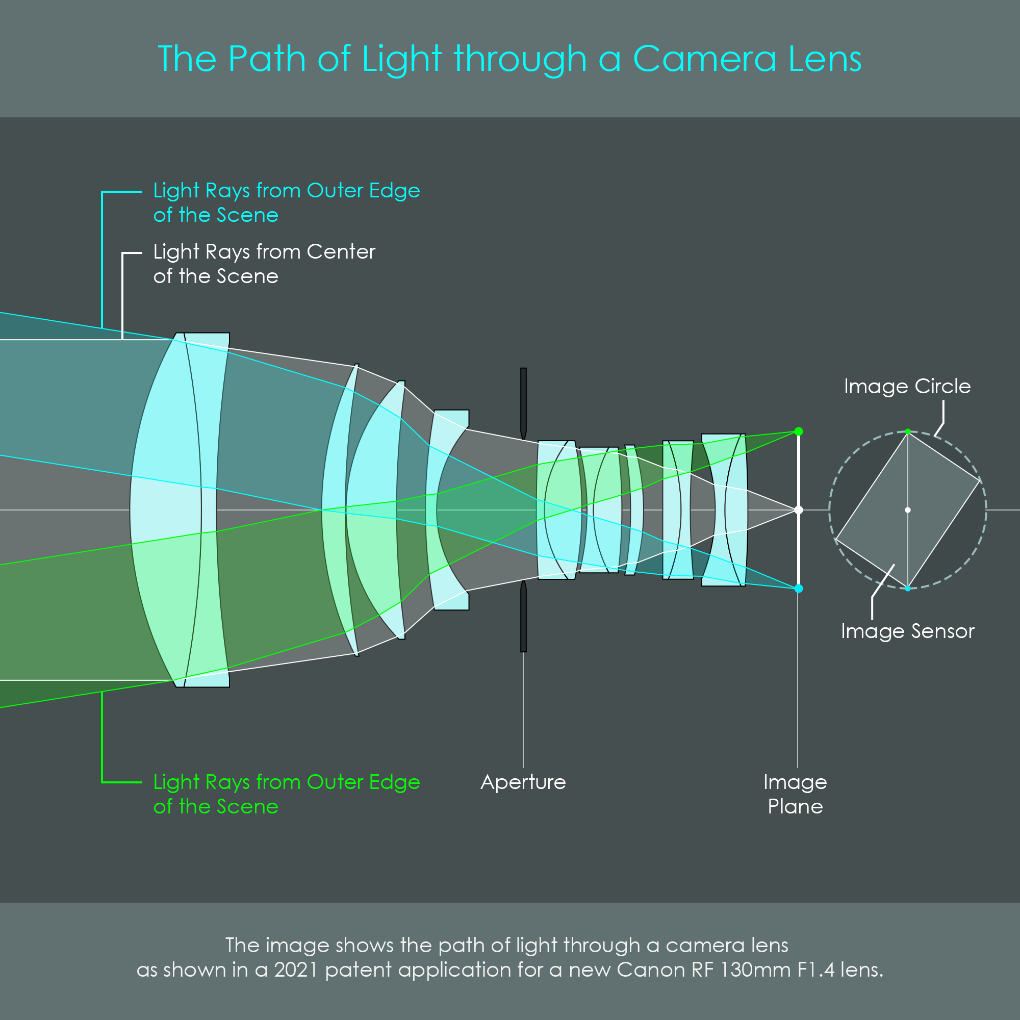
The illustration shows a simulated path of light through a photographic lens consisting of 14 individual lens elements. White light originates from an object point in the center of the scene whereas green and cyan colored light originates from object points at the largest field angles of the scene. The image circle covers a full frame image sensor.
For the sake of completeness, it should be noted that instead of a digital image sensor, cameras have used traditional celluloid film for more than 100 years to record an image. The general concept of image formation naturally also applies to older lenses and older cameras using analog film technology. As this series of chapters is strongly oriented towards fully digital cameras, all of the following descriptions and illustrations are going to include image sensors instead of celluloid film.