The Canon FD 35-70mm 1:4 AF is officially recognized as the world's first autofocus zoom interchangeable lens. At the time of this writing in 2026, the 1981 hardware celebrates its 45th anniversary. Looking at the lens today, it resembles a piece of sci-fi hardware rather than a traditional camera lens. Its uniqueness stems from how it achieved autofocus without any electronic help from the camera body. This article presents the system inside that lens that determines object distance via a fascinating optoelectronic unit.





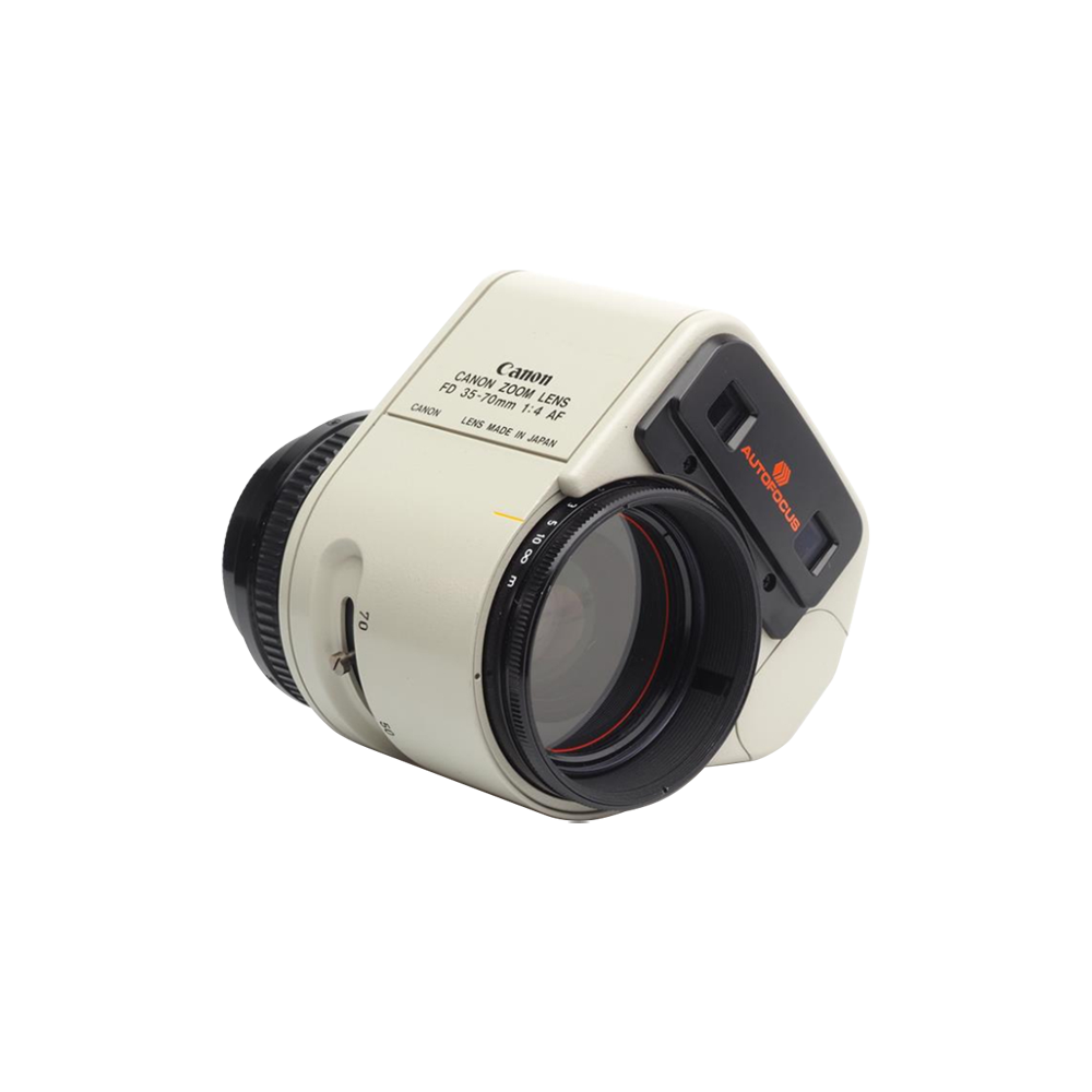
Developed during an era when SLR photography was entirely dominated by manual focusing, this lens introduced a pioneering leap in technological innovation. To achieve autofocus without any electronic assistance from the camera body, Canon engineered a completely autonomous system directly into the lens itself. Its core breakthrough was the revolutionary Solid State Triangulation (SST) technology, which utilized two distinct glass windows to bounce light onto a linear 240-element CCD sensor to calculate distance. Powered by its own pair of AA batteries, the lens could completely focus itself on any standard FD-mount camera body with the press of a single button and a distinctive electronic beep. While its bulky, top-heavy design eventually led Canon to redesign its entire approach to autofocus, this unique lens laid the algorithmic and technical groundwork for modern phase-detection systems, making it a legendary artifact from the dawn of automated photography.
The Canon FD 35-70mm f/4 AF brought unprecedented convenience to an era when FD mount cameras were strictly manual focus. Manual focusing was a constant challenge for many photographers, particularly those struggling with poor eyesight or fast-moving subjects. This revolutionary lens solved that problem by allowing users to completely rely on the single push of a button to instantly achieve perfect focus. By eliminating the guesswork of manual alignment, it acted as a game-changing tool that gave beginners the confidence to take sharp photos, while offering professionals a fast, reliable backup during demanding shoots. The image shows some of the lens features.
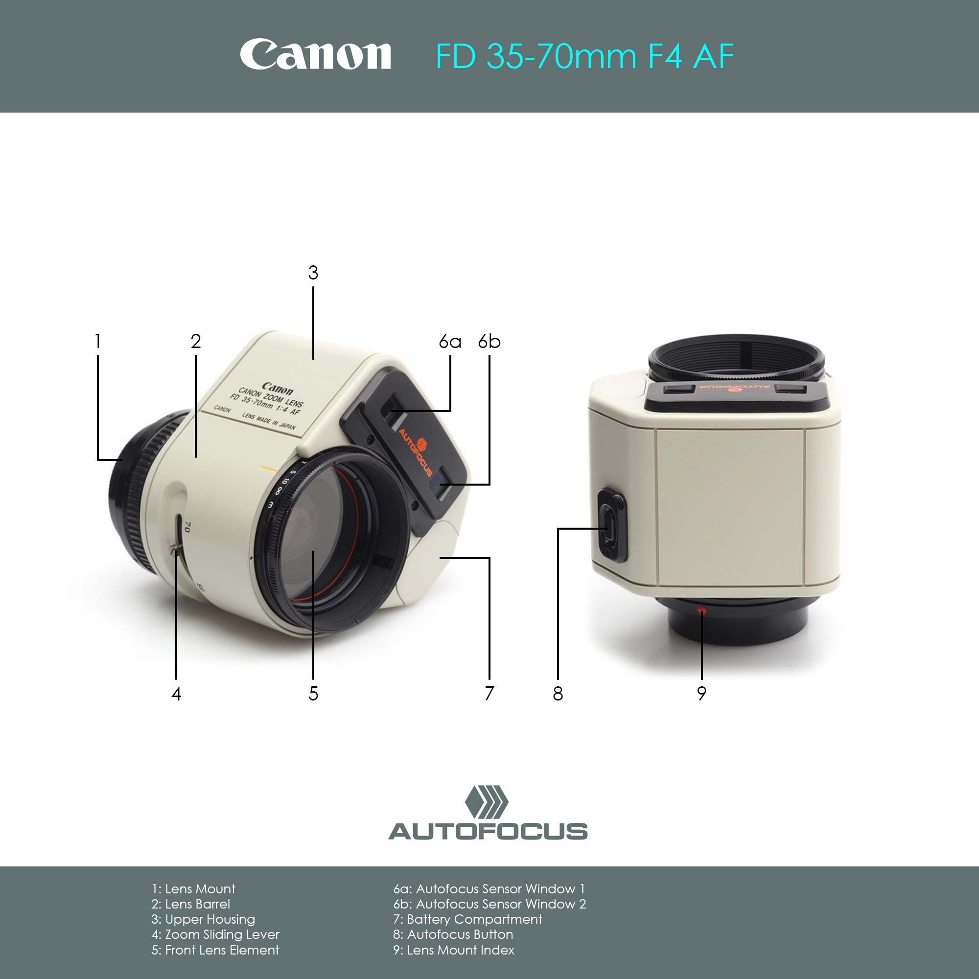
Canon labeled the lens with their CAFS (Canon Auto Focus System) logo. That CAFS badge symbolizes one of the most critical turning points in consumer camera history. Introduced in November 1979, CAFS was the branding and technical designation for Canon's first-generation active infrared triangulation autofocus technology, incorporated in the legendary Canon AF35M camera. Although the technology had changed, Canon used the CAFS symbol on the FD 35-70mm 1:4 AF zoom lens (with the acronym CAFS on the packaging and the description AUTOFOCUS on the lens itself).

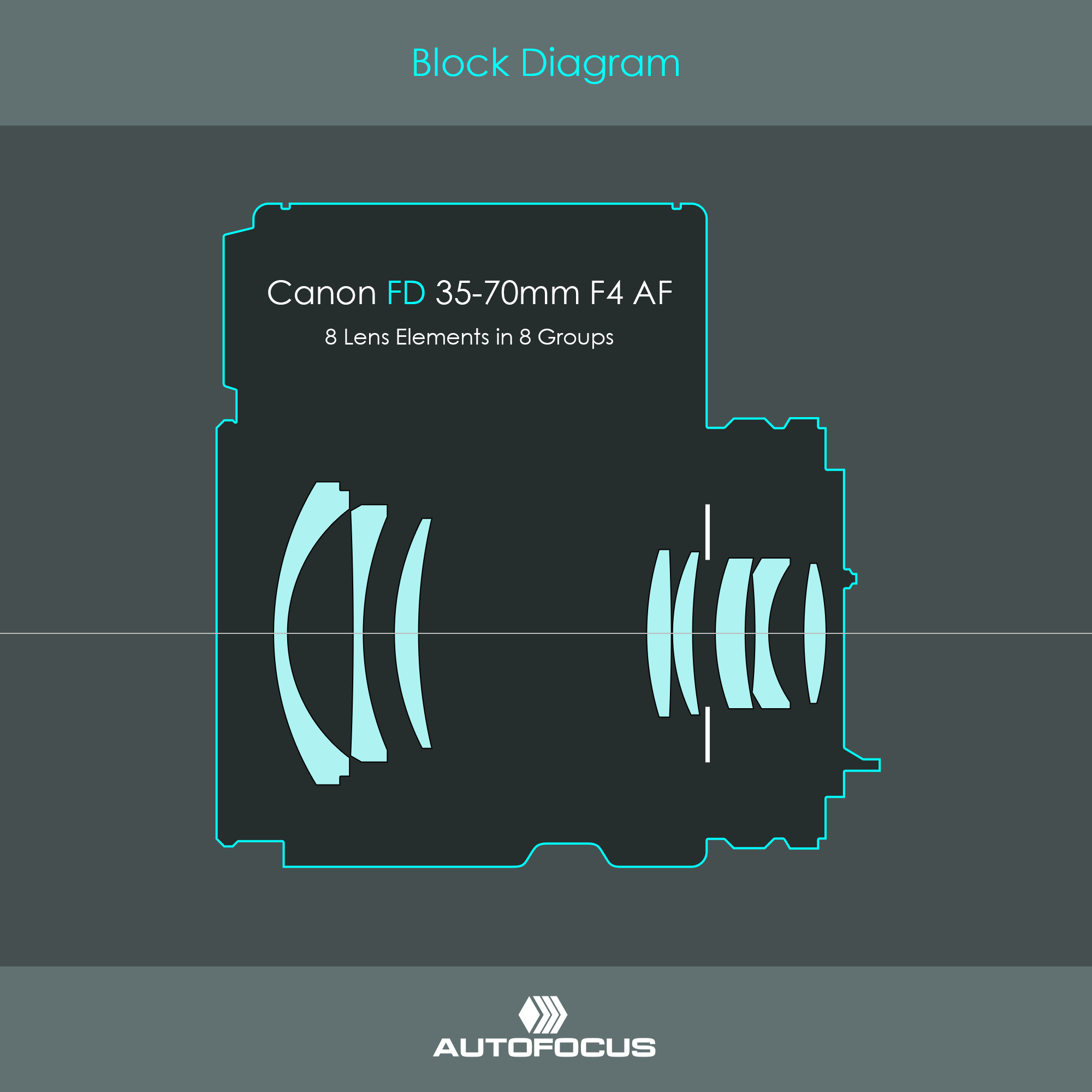
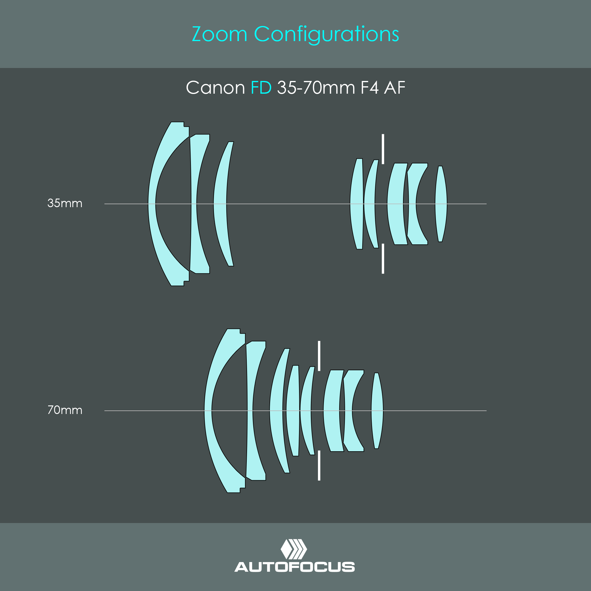
The optical design is based on an older, manual-focus zoom lens from 1979, the Canon FD 35-70mm 1:4 (without AF in its name). Because it was one of Canon's best-selling and most optically reliable zoom lenses of that time, engineers chose its exact 8-element in 8-group optical construction as the foundation for the 1981 autofocus experiment. They simply took the existing glass barrel and built the self-contained Solid State Triangulation (SST) computing housing, motor, and battery compartments directly over it. The illustration shows the block diagram of the lens elements in their wide-angle configuration.
The image shows the positions of lens elements depending on their zoom configurations. You can read more about Canon's zoom systems here.
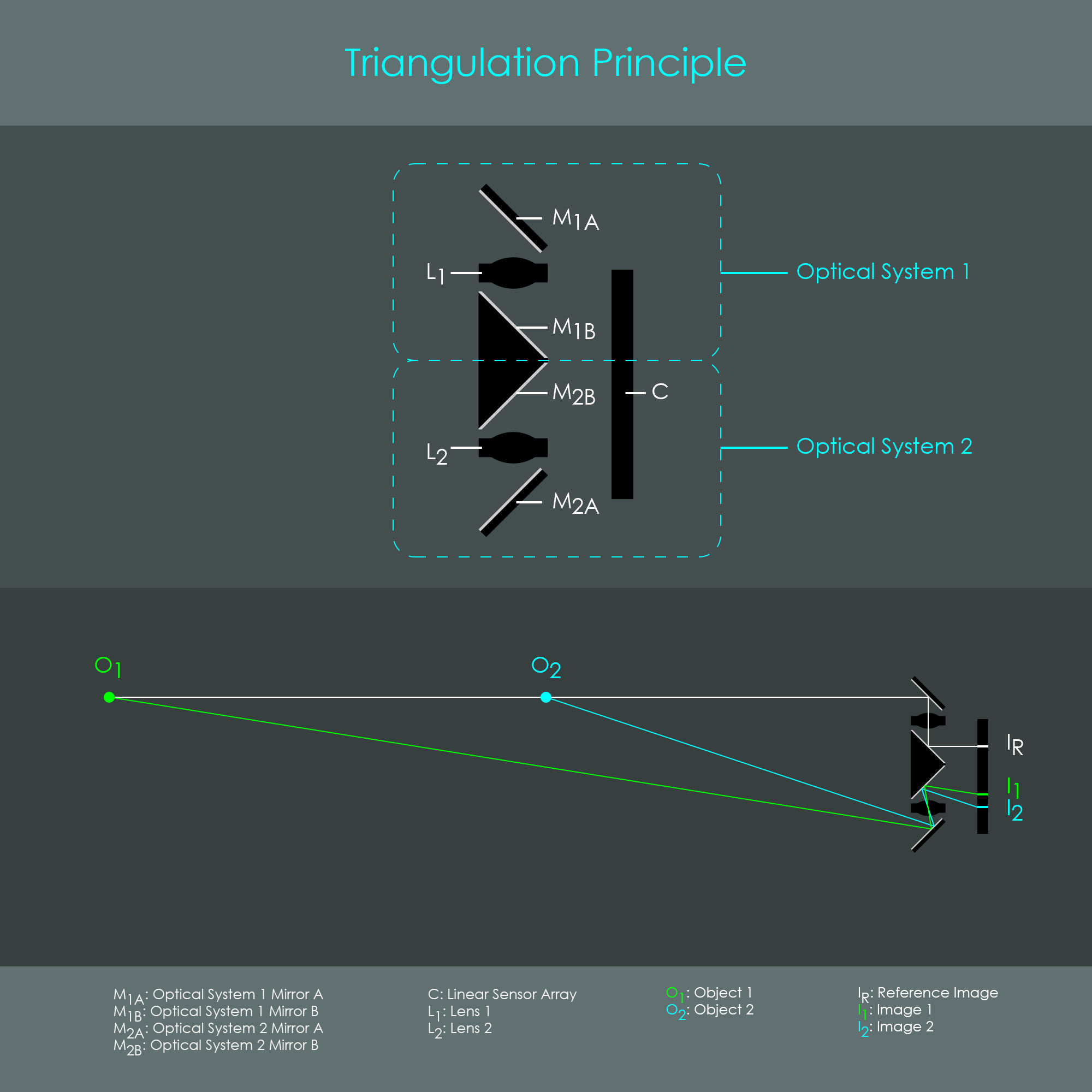
The solid state optical triangulation system operates by analyzing a target subject from two distinct perspectives. Two separate optical channels (optical systems 1 and 2) project dual images of the same object onto a single linear charge-coupled device (CCD) sensor. In this proprietary Canon design, the optical path of optical system 1 serves as a fixed reference channel; consequently, the reference image IR maintains a constant position on the sensor.
Conversely, as the distance between the target object O and the triangulation unit varies, the position of the corresponding image I projected by optical system 2 shifts across the CCD sensor. Specifically, axial movement of the object toward the unit causes the image of optical system 2 to translate toward the outer edge of the sensor ( I2 ), while movement away from the unit shifts it inward ( I1 ).
The lens processing circuitry continuously reads the spatial intensity profile of the CCD. It isolates the image profile (characterized by distinct brightness transitions across a specific pixel array) at the reference point to identify the exact subject currently targeted by the lens. An identical image profile appears on the opposite half of the CCD sensor, offset by a variable distance from the reference point. By measuring this spatial displacement between the two image profiles, the internal electronics precisely calculate the absolute distance to the object.
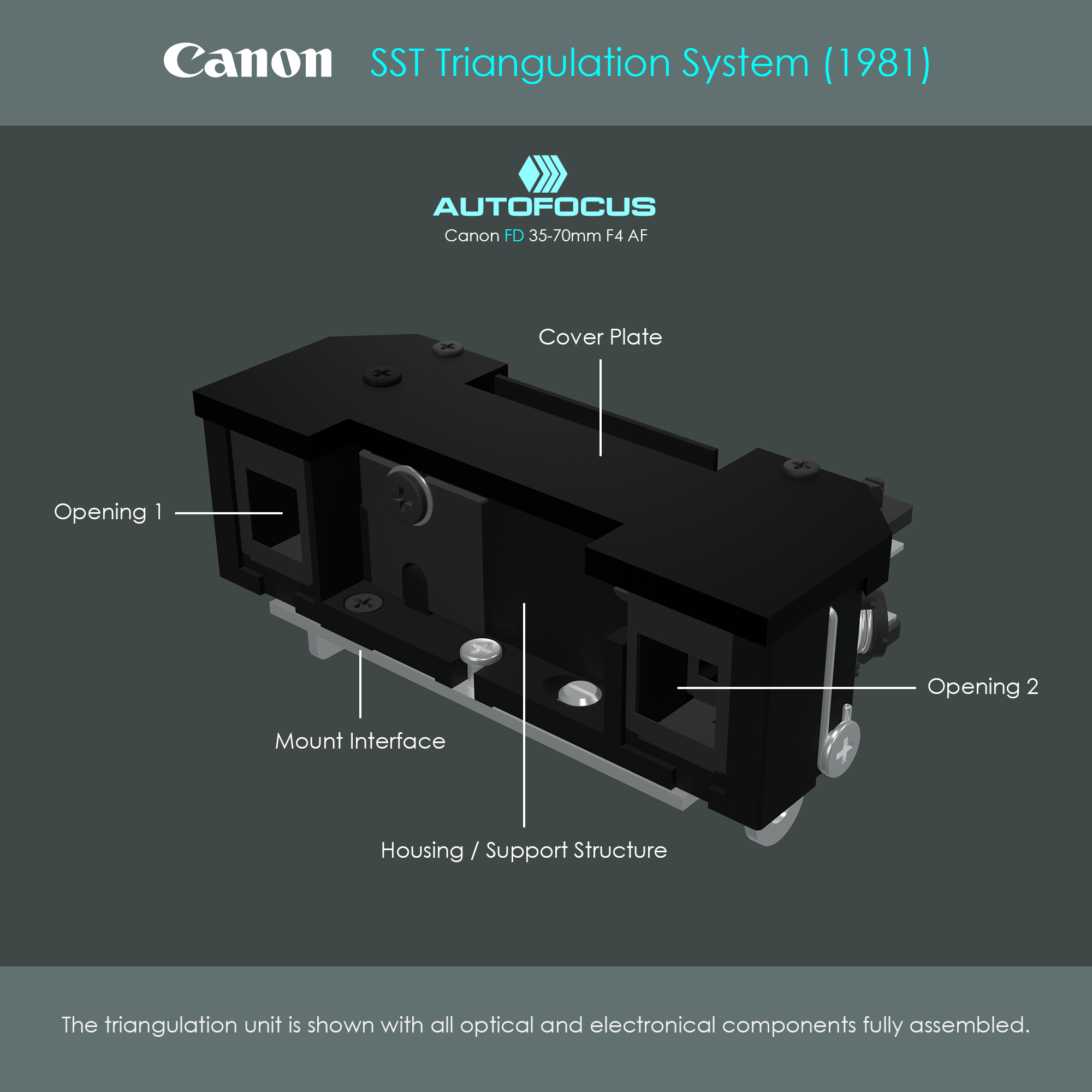
Let's see how this theoretical concept has been brought to life. The autofocus triangulation unit inside the Canon FD 35-70mm 1:4 AF lens consists of a black metal housing with a black plastic cover on top. The center-to-center distance between the two openings is approximately 40 mm. The entire unit is fixed on a metal interface plate that is used to mount it inside the lens' upper housing.
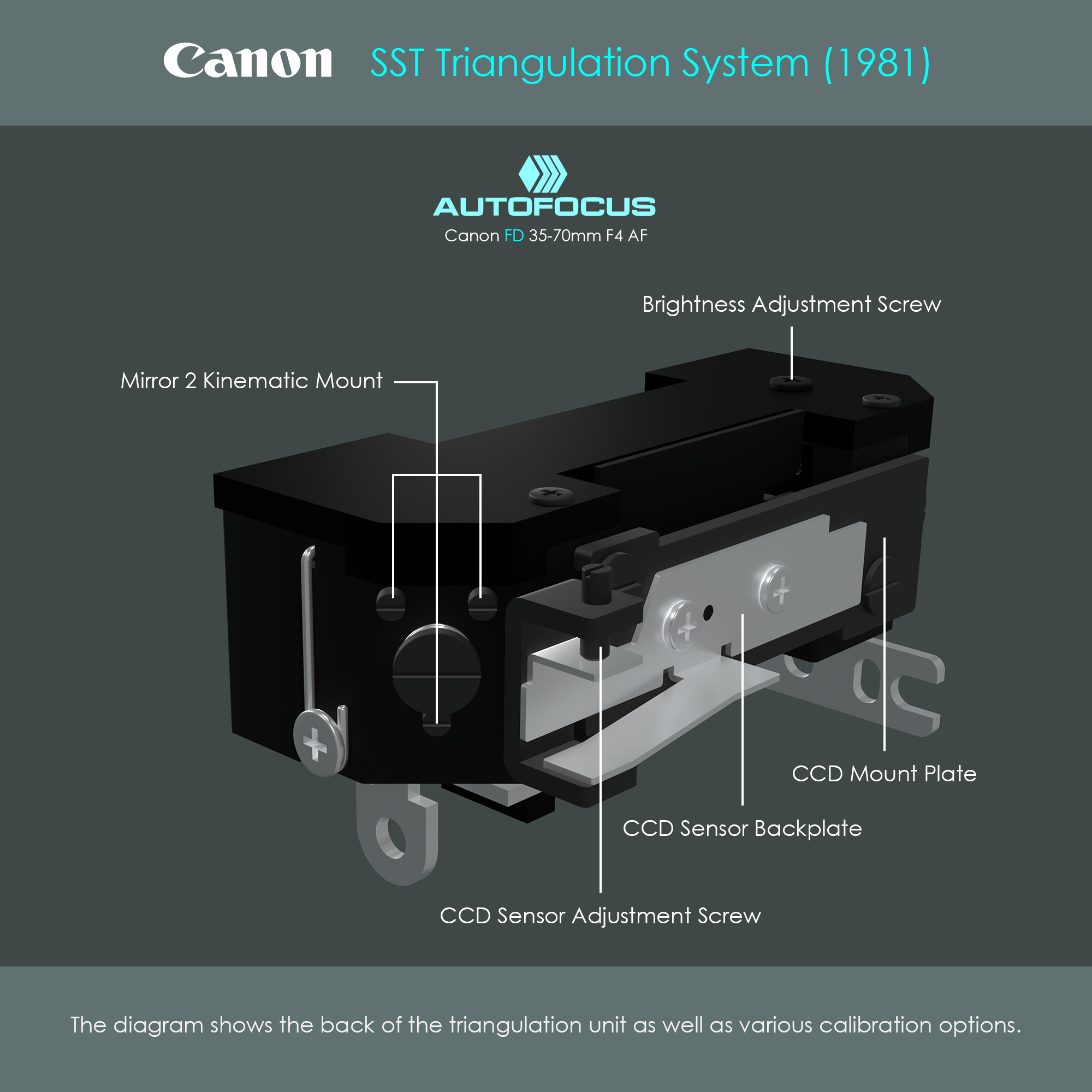
Looking at the back of the triangulation unit shows various screws and springs. Three screws on each side are part of a kinematic mount to perfectly align the small mirrors inside the unit. An adjustment screw is used to bring the CCD sensor in a perfect horizontal position. A brightness adjustment screw is used to balance the brightness of the optical channel 1 to perfectly match the brightness of channel 2. Note that these adjustment screws are not designed to be turned by the user. These types of calibrations are only performed during manufacturing or during repair.
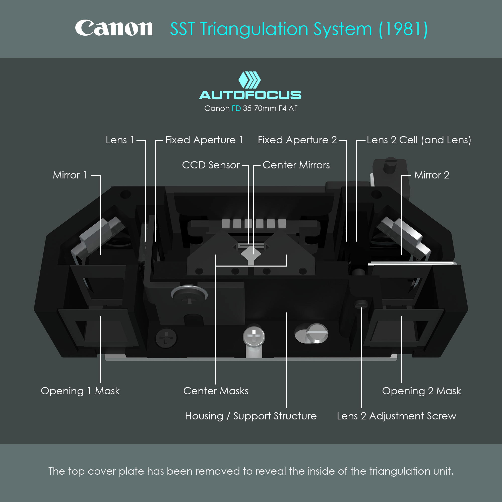
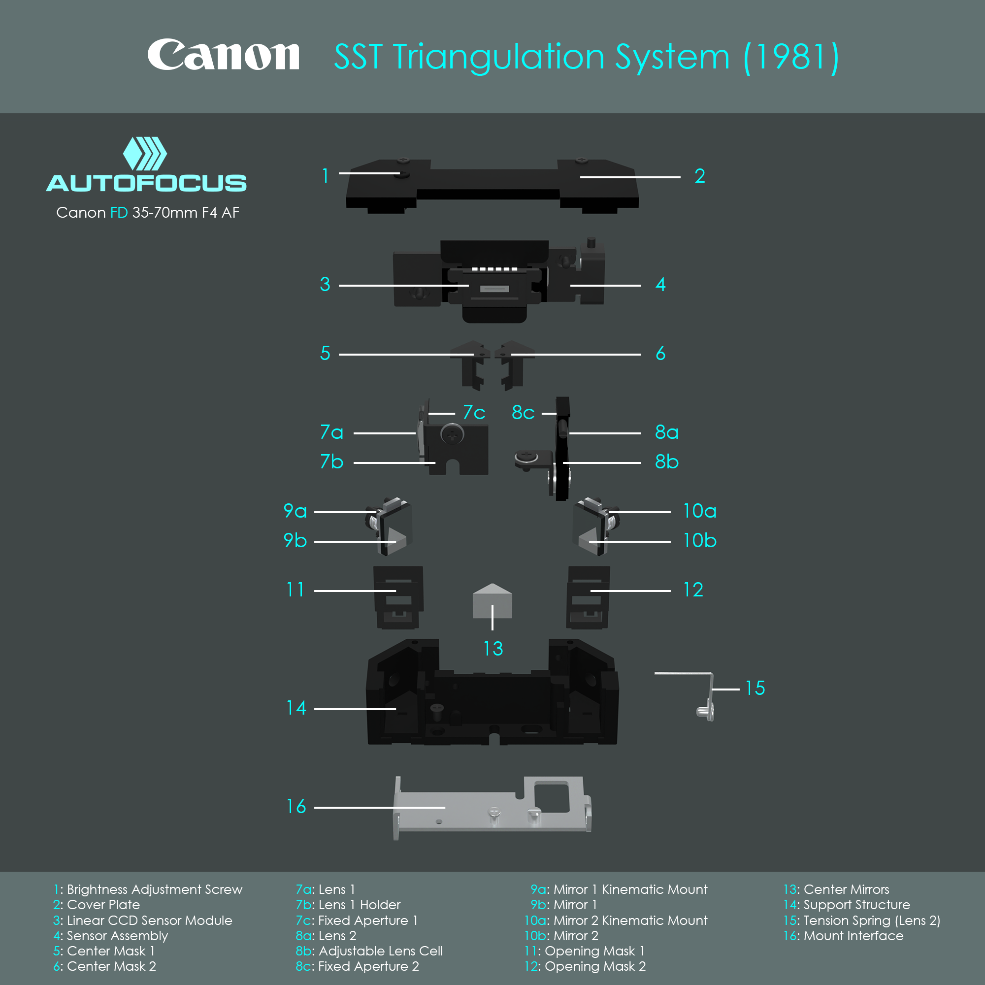
Removing the top cover reveals the optical and electronical components inside the system. The fact that no part is moving during operation gives this solid state triangulation system its name. The optical systems 1 and 2 are arranged symmetrically around the central axis of the triangulation unit. However, due to the various calibration options, some clamps and adjusting screws must be mounted on the housing in a slightly asymmetrical manner. For example, lens 1 is mounted on a fixed bracket, whereas lens 2 is mounted inside a movable lens cell that allows its position to be fine-tuned via the lens 2 adjustment screw.
Various masks are designed to prevent stray light from reaching the sensor. Fixed apertures on each optical system are placed directly behind the lenses, and these serve to control the depth of field, define a sharp entrance pupil, and limit optical aberrations forming on the CCD sensor.
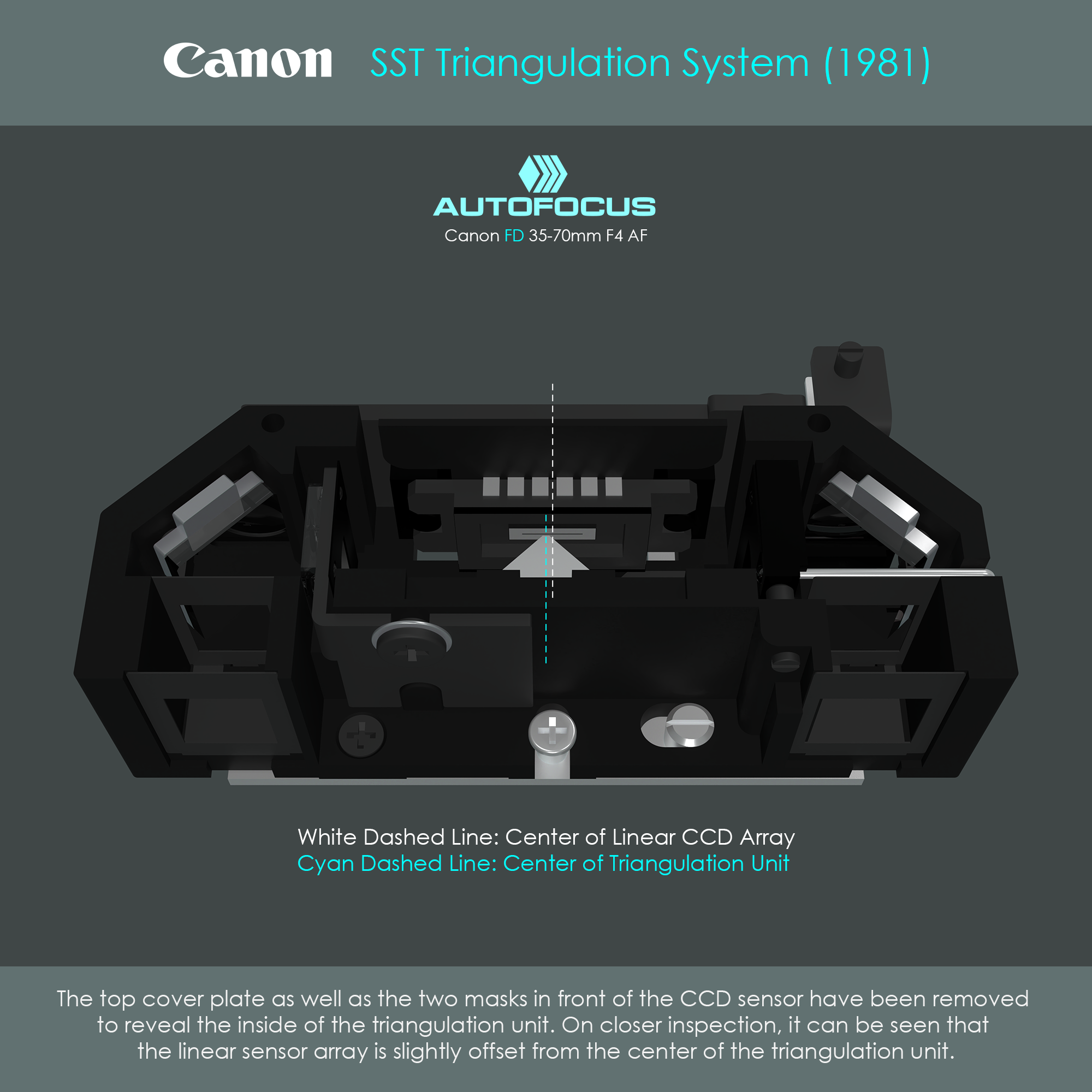
In this illustration, the two masks at the center of the unit have been removed to better view the CCD sensor. On closer inspection, it can be seen that the linear CCD sensor is slightly offset from the center of the triangulation unit. This offset makes sense when looking at the triangulation diagram again. The position of image 1 remains unchanged for all subject distances. It is only image 2 that can shift further away from the center, and therefore the photosensitive array must cover that additional area. Thich is achieved by placing the sensor chip more to the right.
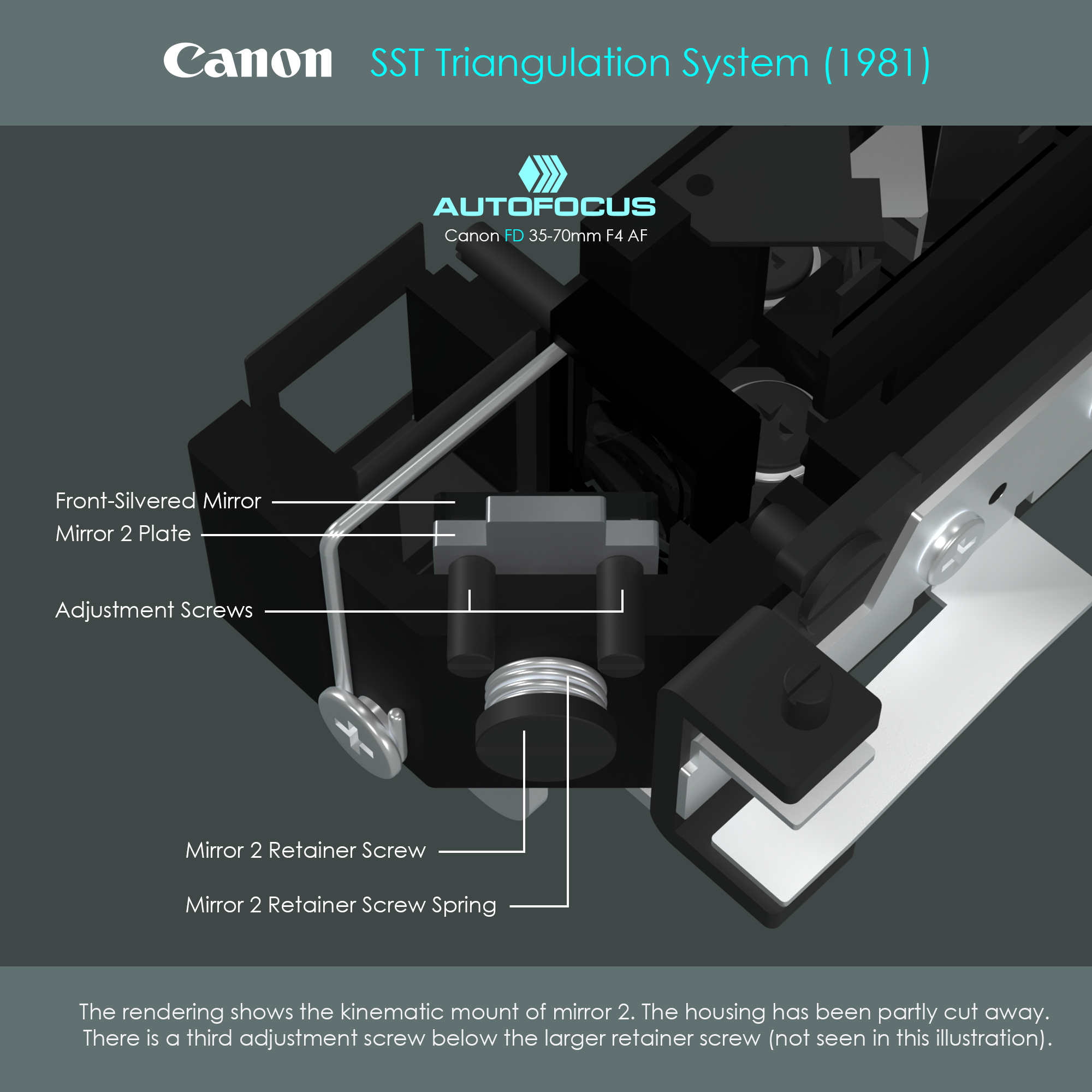
Mirrors 1 and 2 are oriented at 45 degrees relative to the triangulation unit to redirect incident light into lenses 1 and 2, respectively. Precise alignment of these optics is critical to system performance. To enable ultra-fine angular adjustments post-installation, each mirror is integrated into a kinematic mounting system. A spring-loaded mechanism preloads the mirror plate against the outer housing wall, seating it precisely against the tips of three adjustment screws. By adjusting these three points, the mirror can be manipulated in the tip/tilt degrees of freedom within a fine tuning range.
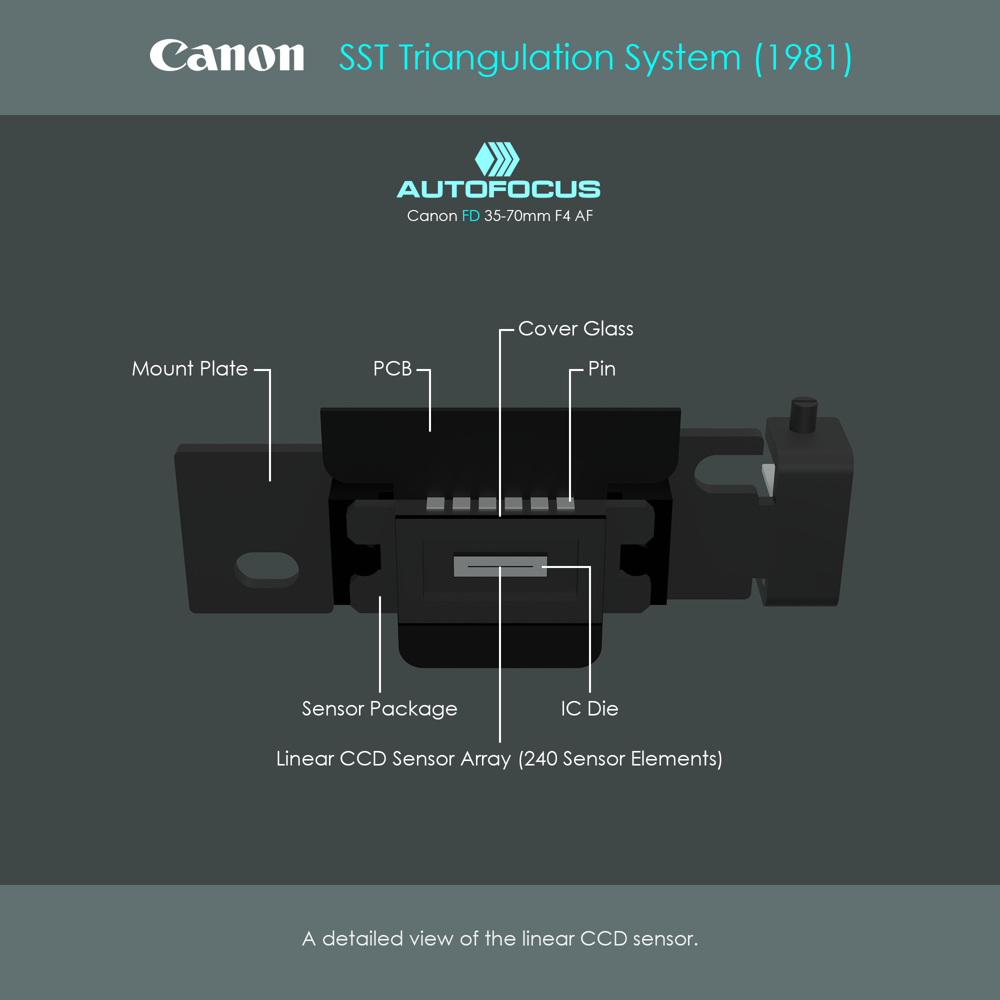
The illustration shows the sensor chip that houses the linear sensor array. The actual photosensitive area is a charge-coupled device that consists of 240 photosensitive elements. The size of thisone-dimensional spatial light meter is only around 4 mm long. The photosensitive area is embedded on the surface of a small integrated circuit die that accomodates amplification and post-processing circuits (image post-processing only, not the actual triangulation calculation). The sensor package is soldered on a printed circuit board from which individual wires lead to the main autofocus circuit board (not shown here).
The illustration below is an exploded view of the triangulation unit discussed above. Note the high degree of symmetry, which is broken only by a few components.
The linear array configuration restricts autofocus detection to a single axis, specifically horizontal to the sensor's orientation. Consequently, when oriented toward a subject composed exclusively of horizontal lines, the sensor cannot identify phase shifts, leading to autofocus failure. The same applies to subjects with little or no contrast at all. Furthermore, as a passive system, its performance depends heavily on sufficient ambient illuminance. An insufficient scene brightness degrades the sensor's signal-to-noise ratio (SNR) below the threshold required for the microprocessor to perform accurate waveform cross-correlation.
The illustration below is an animation of a subject oscillating between two distances from the triangulation unit. You can see the two images formed on the CCD sensor by the two optical systems. The left image is formed by optical system 1 and serves as the reference profile that does not change its position. The right image is formed by optical system 2 and changes its position depending on the subject. This animation is a real ray-tracing where object light was passed through the three-dimensional triangulation unit.