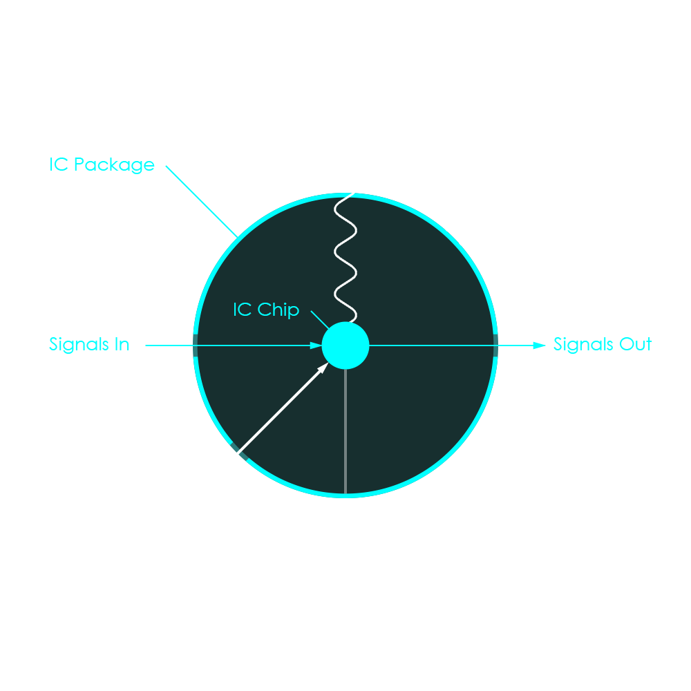
The packaging of a microchip satisfies many requirements. It is typically made from materials that are capable of protecting the silicon chip and tiny bond wires from physical damage, dust and corrosion. Therefore, very common types of IC packages (DIP, QFP, SOP) are formed by epoxy resin that is moulded around the silicon die and pressed into the desired shape of the package. This completely seals the sensitive structures and protects them from environmental attack. Other package types (LGA) often use fiber glass baseplates and metal covers that are glued to the base to achieve a similar protection. It is important, however, that the silicon chip is not completely isolated from the outside: Power supply and electronic signals should not be affected or interrupted when passing through the IC package. In fact, the case must include a capable interface that the IC chip can use to interact with the surrounding electronics. The package must also be fabricated from a material with a high thermal conductivity so it can best dissipate the heat generated by the IC. The package also offers structural support for the entire component, holding the pins in place and allowing the component to be pressed into sockets without bending. Lastly, it is a requirement that an IC package does not constrain the integrated circuit in terms of performance, size, weight, testability, reliability, and cost. To summarize all the functions, the package can be described as a protective enclosure of an integrated circuit to guarantee component functionality and long-term reliability.
The IC package is a physical barrier against following environmental influences which might lead to IC failure:
Since the 1970s, a large variety of IC packages has evolved. Although some package types have been introduced over 40 years ago, they are still widely used today. Dual InLine Packages (DIP), Small Outline Packages (SOP) or Quad Flat Packages (QFP) can still be found in today’s electronic devices. Land Grid Array (LGA) packages are still first choice in today’s high performance computer systems. Most recent developments including Interposer-based 2.5D ICs (2.5D IC) and 3D ICs (3D IC) are optimized packages for applications in tiny devices such as smartphones and smartwatches. The timeline gives an overview of microchip packaging developments over the past years.

Integrated circuits almost always produce a certain amount of heat. The heat mainly is generated by electric currents flowing through all the conductors and transistors on the surface of the silicon die. Factors like the type of integrated circuit (number of transistors, operating voltage, clock speed) and the load applied to the device may either lead to some low warming or to massive heat generation.
Silicon chips that are used in commercial devices are often specified for temperatures of up to 90 °C. There are chips that will always remain within the temperature limits during their operation as the amount of heat that is produced is relatively small and the chip package is able to dissipate that heat by convection and radiation. These devices usually do not need additional cooling. In case, however, that a semiconductor should produce more heat than the chip package can disspate on its own, heat will accumulate and eventually cause the chip to exceed its temperature limits. To protect integrated circuits from permanent damage by overheating (thermal degradation), the IC package's ability to dissipate heat must be increased. There are two basic approaches to optimize the heat transfer: Installing a passive heatsink or an active heatsink.
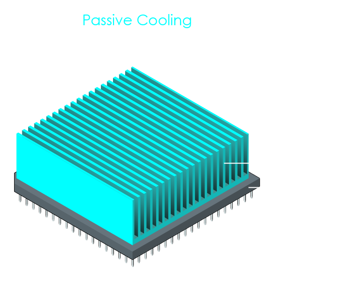
A passive heatsink is a cooling device that is typically made of a thermally conductive material such as copper or aluminum. The purpose of applying such a passive heatsink to the chip is to move heat away (conduction inside the material) from the device into the air stream, where it can be carried away (convection). In addition, many heatsinks are painted black to increase the effect of heat radiating off to the environment (infrared radiation), adding to the cooling effect. The design of a heatsink normally has fins or other protrusions to increase the surface area, thus increasing its ability to dissipate heat into the air. To improve heat transfer even more, a thermal interface material (thermal paste or thermal pad) is almost always applied between the IC chip and the heatsink. This is done to fill in microscopic irregularities and indentations in the surfaces of the chip package and the heatsink that might otherwise result in non-heat-conductive air gaps. The thermal compound fills in all air gaps and ensures an even heat transfer. With no moving parts, passive cooling is considered extremely reliable and very cost-efficient.
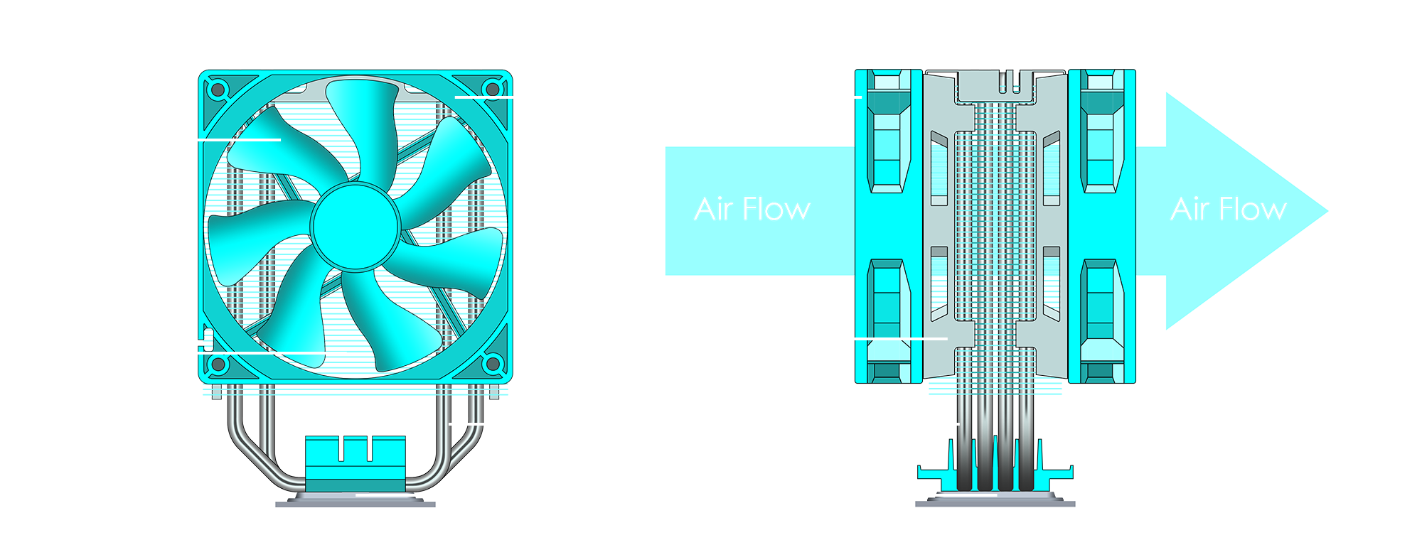
In some cases, a passive heatsink cannot remove an IC chip's heat fast enough. To increase the heatsink's ability to transfer heat away from the IC, a fan can be added directly to the heatsink, making the heatsink an active component. The fan has the purpose to provide a constant air flow to run through the heatsink fins, constantly providing fresh air so that the heatsink can dissipate even large amounts of heat. While delivering a high cooling performance, active heatsinks carry the drawbacks of reduced reliability, higher system cost, higher operating power, and noise generation.

Over the past decades, cooling devices have been highly optimized to increase their cooling efficiency while minimizing their overall size, energy consumption, and noise. One invention that improved the heat transfer is heat pipes. These are small copper pipes that have a coating of copper powder on the inside, and are filled with a coolant fluid (often based on distilled water). The heat transfer works by the hot IC evaporating the coolant fluid where the heat pipes touch the IC. The evaporated water now is a hot gas that rises inside the pipes to areas where the cool heatsink touches, and the coolant therefore condenses back to water. This condensation transfers the heat to the heatsink where it is cooled by air flowing through the fins. Ater the condensation, water runs down the inside of the heatpipes to collect at the lower end where the evaporation-condensation cycle starts again.