An illustrated chronological story about how Canon autofocus systems and viewfinders went from a single AF point (1987) to 191 AF points (2020).
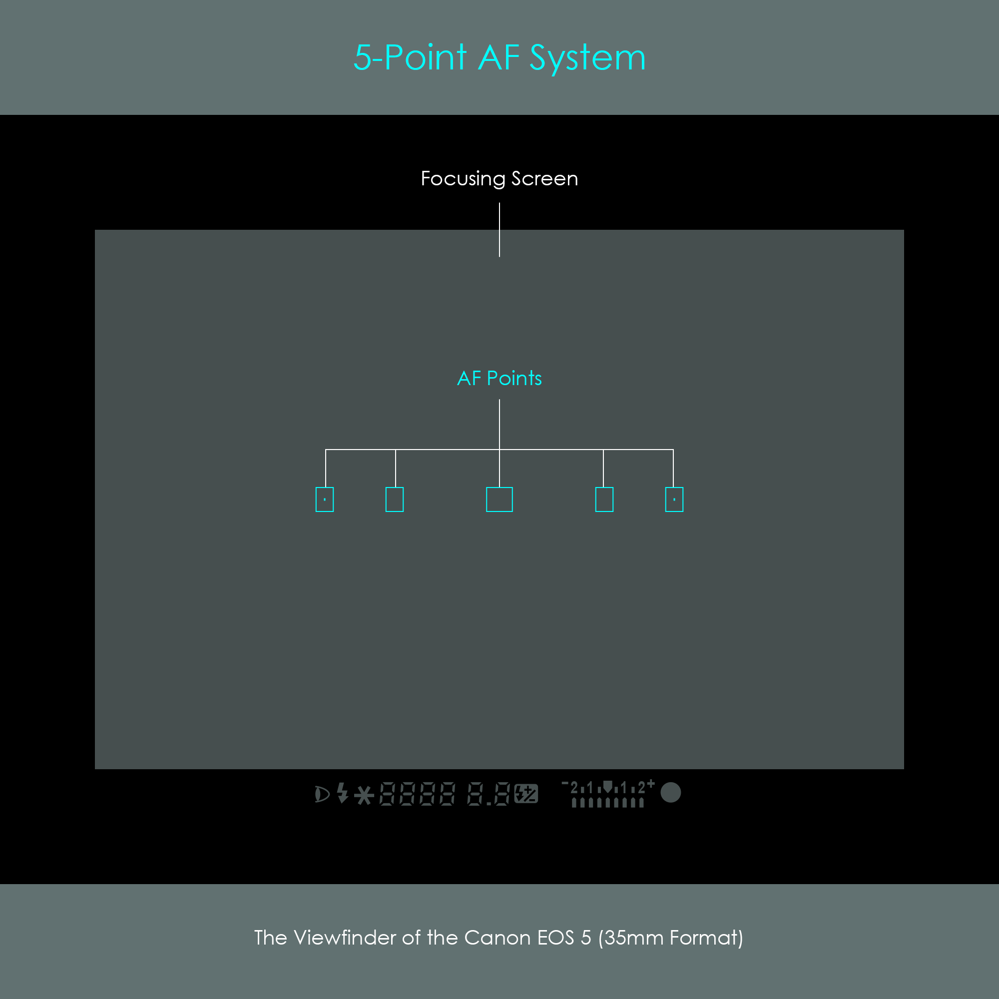
The system offered an increased number of AF points. With five AF points arranged horizontally across the viewfinder, this type of AF point coverage was also described with the term wide-zone focusing.
Each AF sensor was indicated with a small frame. The center was shaped as a uniform square whereas the remaining four AF sensors were rectangles, oriented with their long side vertically.
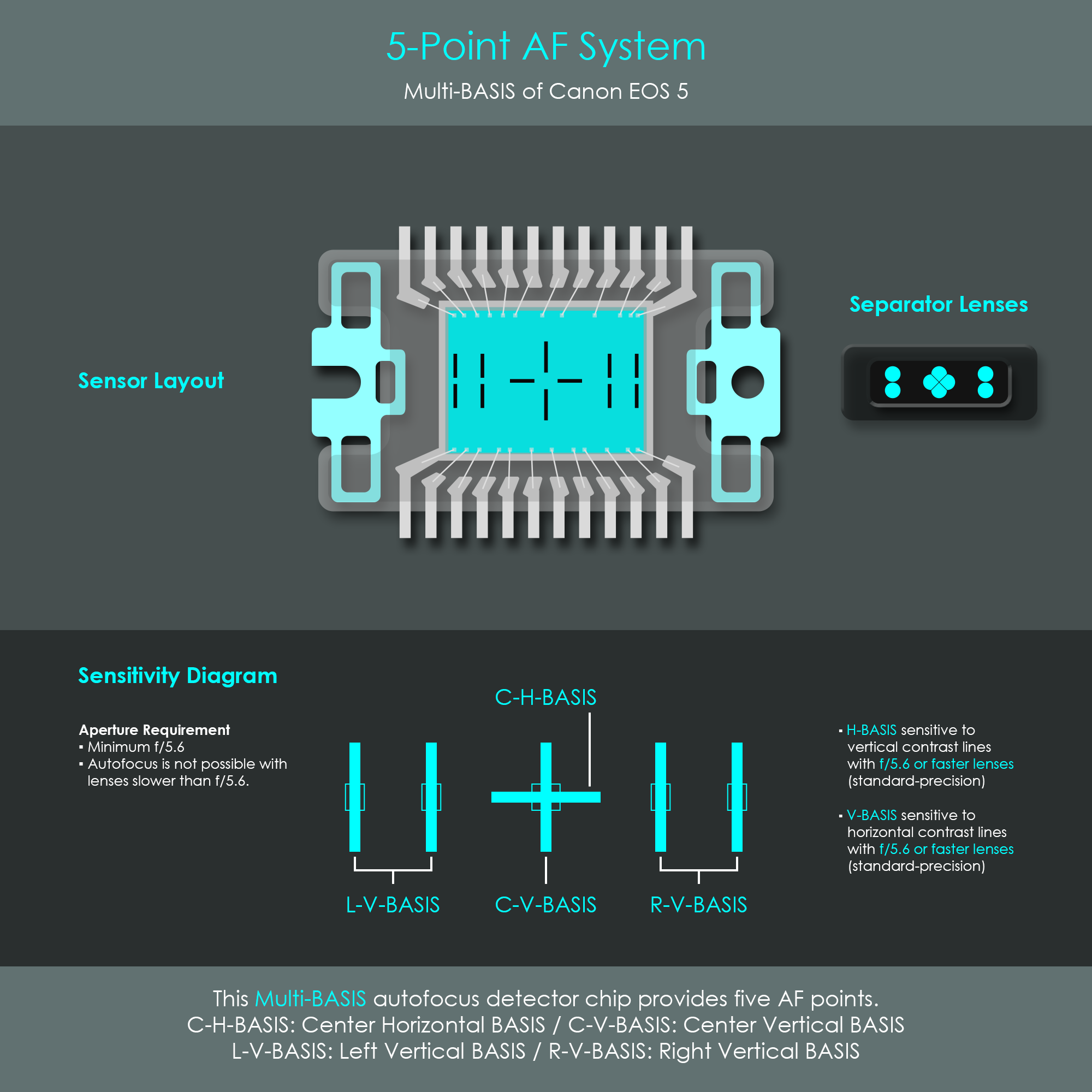
In principle, this sensor chip used the same design and structure as the previous Multi-BASIS sensors. Package size was 14.0 mm × 8.2 mm. The main difference, however, lied in the number of detectors. The C-V-BASIS (center-vertical-BASIS) used two 42-bit and the C-H-BASIS (center-horizontal-BASIS) used two 32-bit detectors. The two L-V-BASIS and two R-V-BASIS (left-vertical-BASIS and right-vertical-BASIS) all used pairs of 32-bit detectors.
The center AF point was a cross-type detector sensitive to vertical and horizontal contrast lines. Each of the outer AF points used a vertical pair of detectors sensitive to horizontal contrast lines. All sensors required a minimum aperture of f/5.6 to operate (standard-precision). There was no f/2.8 (high-precision) detector available.
The system had an AF working range of EV 0 - 18 at ISO 100.
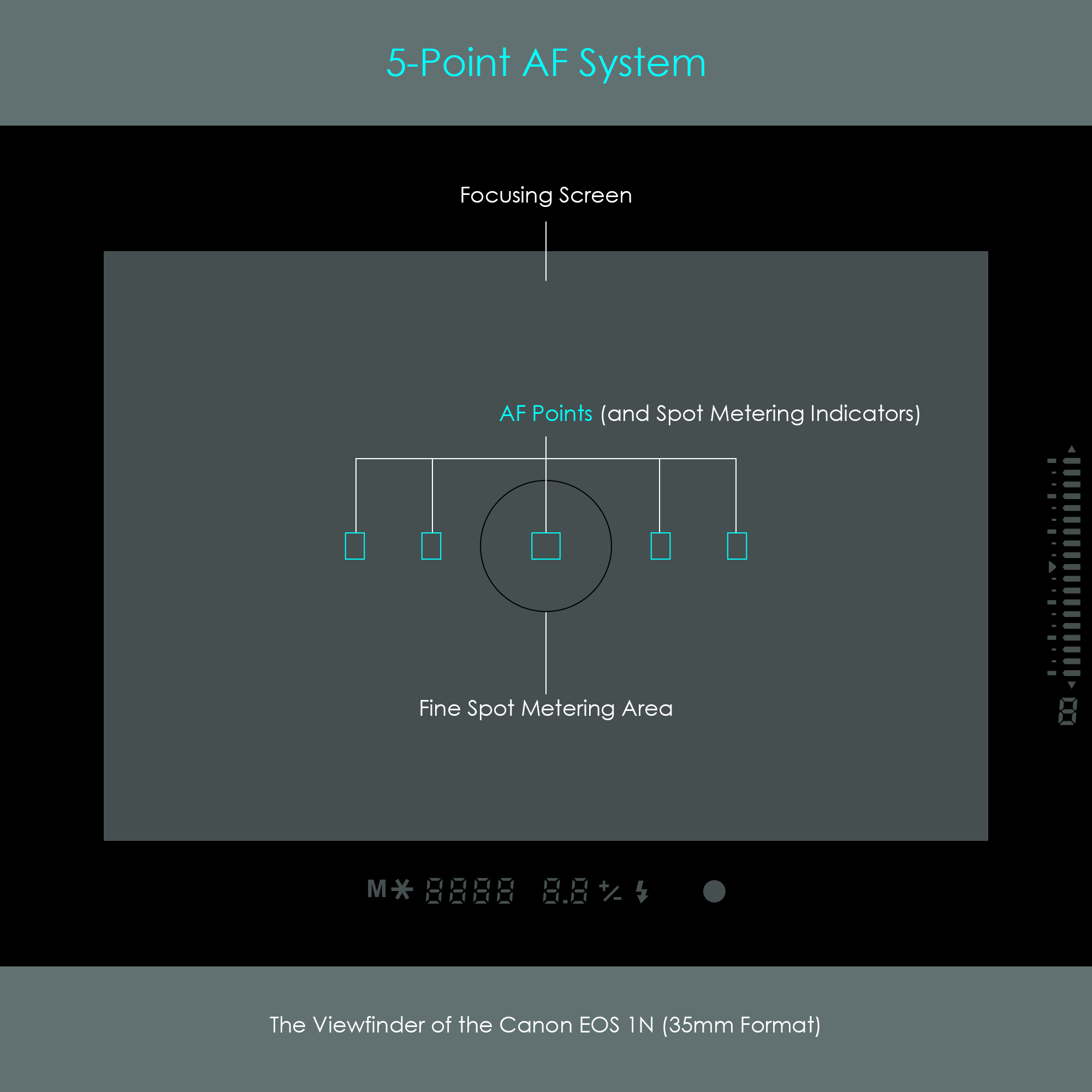
This AF system combined the high-precision vertical detector (as already used in the Canon EOS-1) with the 5-point multi-AF-design (as already used in the Canon EOS 5). It was this combination why Canon called this the High-Precision Multi-BASIS sensor. In addition, this new AF system had incorporated a fine-spot metering sensor directly onto the AF chip. Further improvements have been made on the rangefinding circuitry inside the active area, which resulted in a significant reduction in processing time.
Each AF sensor was indicated with a small frame. The center is shaped as a uniform square whereas the remaining four AF sensors were displayed as rectangles, oriented with their long side vertically. The fine spot metering area was indicated as a small circle at the center of the viewfinder.
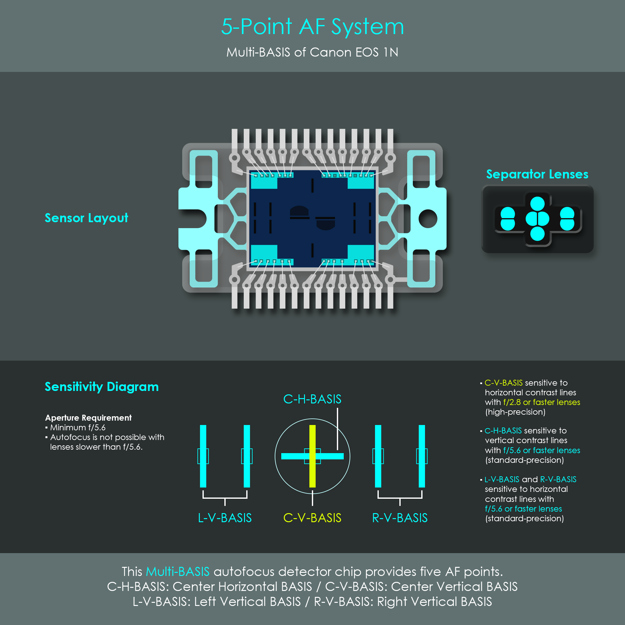
This AF chip used a similar 14.0 mm × 8.2 mm package than that of the EOS 5. The sensor array's layout resulted from the combination of various technologies that had already been used in previous AF systems:
Other adjustments had to be applied to the overall optical assembly including the separator lenses to match the array of detector lines. The integration of the fine-spot metering sensor into the chip resulted in a concentration of functionality, but also an addition of four pins. In order to keep the same size chip package as used in the EOS 5, a small adjustment to the pin size was required: The 0.8 mm pin pitch (EOS 5) was reduced to 0.65 mm (EOS-1N).
The center AF point worked in the same way as the AF point of the Canon EOS-1. The C-H-BASIS was designed for use with lenses having a maximum aperture of f/5.6 or faster (standard-precision) and was sensitive to vertical contrast lines. If a lens with a maximum aperture of f/2.8 or faster was attached to the camera, that center AF point became a cross-type sensor with the C-V-BASIS component being a high-precision detector. The other AF points (L-V-BASIS and R-V-BASIS) were vertical detectors, sensitive to horizontal contrast lines. These were designed for use with lenses having a maximum aperture of f/5.6 or faster (standard-precision). Autofocus was not possible with lenses slower than f/5.6.
The system had an AF working range of EV 0 - 18 at ISO 100.
Amplifiers can improve the signal-to-noise ratio (SNR) by increasing the signal strength relative to the noise floor. For that reason, each light receptor cell inside the detector strips was coupled with an own amplifier. In addition to these individual cell-amplifiers, another amplifier circuit with a gain factor of 20 was designed on-chip to further improve the system's sensitivity and SNR.
In automatic AF point selection mode, the camera's AF processor always carried out rangefinding calculations simultaneously for the H-BASIS and all V-BASIS detectors. This not only applied to the AF system of the Canon EOS-1N but practically to all autofocus systems with multiple sensors. The EOS-1N incorporated a dedicated AF processor with a clock speed of 12 MHz. While this clock speed was identical with the processor speed of the Canon EOS-1, the minimum AF calculation time was reduced from 33 µs (EOS-1) to 17 µs (EOS-1N) despite offering five times the number of AF points.